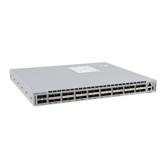
Arista DCS-7050QX-32S Quick Start Manual
7000 series 1 ru (gen 3) data center switches
Hide thumbs
Also See for DCS-7050QX-32S:
- Quick start manual (27 pages) ,
- Quick start manual (23 pages) ,
- Quick start manual (56 pages)

Related Manuals for Arista DCS-7050QX-32S


Summary of Contents for Arista DCS-7050QX-32S
-
Page 1: Quick Start Guide
Quick Start Guide 7000 Series 1 RU (Gen 3) Data Center Switches Arista Networks www.arista.com PDOC-00041-13... - Page 2 © Copyright 2017 Arista Networks, Inc. The information contained herein is subject to change without notice. Arista Networks and the Arista logo are trademarks of Arista Networks, Inc in the United States and other countries. Other product or service names may be trademarks or service marks of others.
-
Page 3: Installation Process
Chapter 1 Overview Scope This guide is intended for properly trained service personnel and technicians who need to install the following Arista Networks Data Center Switches: DCS-7050QX-32S DCS-7060CX-32S DCS-7050TX-96 DCS-7280SE-72 DCS-7050SX-64 DCS-7050TX-72Q DCS-7280SR-48C6 DCS-7280QR-C36 DCS-7050SX-72 DCS-7050TX-48 DCS-7050QX2-32S DCS-7280TR-48C6 DCS-7050SX-96 DCS-7050TX-64... -
Page 4: Safety Information
Aucune pièce réparable par l'utilisateur à l'intérieur. Confiez toute réparation à un technicien qualifié. Safety Information Refer to the Arista Networks document Safety Information and Translated Safety Warnings available at: www.arista.com/support/docs/eos Obtaining Technical Assistance Any customer, partner, reseller or distributor holding a valid Arista Service Contract can obtain technical support in any of the following ways: •... - Page 5 Overview Obtaining Technical Assistance Important! No user serviceable parts inside. Refer all servicing to qualified service personnel. Aucune pièce réparable par l'utilisateur à l'intérieur. Confiez toute réparation à un technicien qualifié. Quick Start Guide: 7000 Series 1 RU-Gen 3 Data Center Switches...
-
Page 6: Specifications
Specifications Overview Specifications Table 1-1 lists the specifications of Arista Data Center switches covered by this guide. Table 1-1 Switch Specifications Size (W x H x D) DCS-7050QX-32S 44.5 x 4.4 x 40.6 cm (19 x 1.75 x 16 inches) DCS-7050SX-64 44.5 x 4.4 x 40.6 cm (19 x 1.75 x 16 inches) - Page 7 Power Input (DC Power) PWR-500-DC -48 to -60 VDC, 15 A PWR-1900-DC -48 to -60 VDC, 24 A Power Draw DCS-7050QX-32S 150 W / 300 W (Typical / Maximum) DCS-7050SX-64 140 W / 220 W DCS-7050SX-72 144 W / 276 W...
- Page 8 Specifications Overview Quick Start Guide: 7000 Series 1 RU-Gen 3 Data Center Switches...
-
Page 9: Site Selection
Chapter 2 Preparation Site Selection The following criteria should be considered when selecting a site to install the switch: • Temperature and Ventilation: For proper ventilation, install the switch where there is ample airflow to the front and back of the switch. The ambient temperature should not go below 0° or exceed 40°C. - Page 10 Tools and Parts Required for Installation Chapter 2: Preparation Figure 2-1: Airflow Direction Labels Important! The power input plug-socket combination must be accessible at all times; it provides the primary method of disconnecting power from the system. La combinaison de la puissance-prise d’entrée doit être accessible en tout temps ; Il fournit le principal moyen de coupure d’alimentation du système.
- Page 11 Chapter 2: Preparation Electrostatic Discharge (ESD) Precautions Electrostatic Discharge (ESD) Precautions Observe these guidelines to avoid ESD damage when installing or servicing the switch. • Assemble or disassemble equipment only in a static-free work area. • Use a conductive work surface (such as an anti-static mat) to dissipate static charge. •...
- Page 12 Electrostatic Discharge (ESD) Precautions Chapter 2: Preparation Quick Start Guide: 7000 Series 1 RU-Gen 3 Data Center Switches...
-
Page 13: Rack Mounting The Switch
Important! The rack mounting procedure is identical for all switches covered by this guide. Illustrations in this chapter depict the mounting of a DCS-7050QX-32S switch. Les procédure de montage du bâti est identique pour tous les commutateurs visés par ce guide. Illustrations dans ce chapitre montrent le montage d’un interrupteur de DCS-7050QX-32S. • Section 3.1 provides instructions for mounting the switch in a two-post rack. - Page 14 Two-Post Rack Mount Chapter 3: Rack Mounting the Switch 3.1.1 Attaching Mounting Brackets to the Chassis This procedure attaches mounting brackets to the switch chassis (Figure 3-3). Step 1 Align the mounting brackets with the attachment pins to obtain the desired mounting position. Step 2 Place the bracket flush on the chassis with attachment pins protruding through key-openings.
- Page 15 Chapter 3: Rack Mounting the Switch Two-Post Rack Mount 3.1.2 Inserting the Switch into the Rack This procedure attaches the switch to the rack (Figure 3-4). Step 1 Lift the chassis into the rack. Position the flanges against the rack posts. Step 2 Select mounting screws that fit your equipment rack.
- Page 16 Four-Post Rack Mount Chapter 3: Rack Mounting the Switch Four-Post Rack Mount The switch is mounted onto a four-post rack by assembling two rails onto the rear posts, sliding the switch onto the rails, then securing the switch to the front posts. The installation kit provides the following four-post mounting parts: •...
- Page 17 Chapter 3: Rack Mounting the Switch Four-Post Rack Mount 3.2.1 Attaching Mounting Brackets to the Chassis Figure 3-7 displays the front bracket alignment for mounting the switch into a four-post rack. Figure 3-7: Attaching the Mounting Brackets to the Switch Chassis Attaching the brackets: Front mount This procedure attaches mounting brackets to the switch chassis as depicted by Figure...
- Page 18 Four-Post Rack Mount Chapter 3: Rack Mounting the Switch 3.2.2 Assembling the Rails onto the Equipment Rack Rail-rods and rail-slides assemble into two identical rails. Each rail connects a front post to a rear post. When the rails are installed, the switch slides on the rails into the rack. Each bracket includes a screw that attaches the switch to the rail.
- Page 19 Chapter 3: Rack Mounting the Switch Four-Post Rack Mount Step 2 Attach rail to the right rear rack post by inserting rod-end rack plugs into post slots (Figure 3-10, Inset A). The slide assembly must be inside the right posts, relative to the left rack posts.
- Page 20 Four-Post Rack Mount Chapter 3: Rack Mounting the Switch 3.2.3 Attaching the Switch to the Rack After the rails are installed, the switch slides on the rails into the rack. Each bracket includes a thumb screw that attaches the switch to the rail. Step 1 Lift the switch into the rack and insert the mounting brackets into the slide rails.
-
Page 21: Cabling The Switch
Chapter 4 Cabling the Switch Grounding the Switch After mounting the switch into the rack, connect the switch to the data center ground. Figure 4-1 displays the location of the grounding pads located on the bottom corners of the rear panel for the models that have no management ports on the rear panel. -
Page 22: Connecting Power Cables
Connecting Power Cables Chapter 4: Cabling the Switch Connecting Power Cables Important! Installation of this equipment must comply with local and national electrical codes. If necessary, consult with the appropriate regulatory agencies and inspection authorities to ensure compliance. Installation de cet équipement doit être conformes aux codes électriques locaux et nationaux. Si nécessaire, consulter les organismes de réglementation appropriés et des autorités de contrôle pour assurer la conformité. -
Page 23: Dc Power Supplies
Chapter 4: Cabling the Switch Connecting Power Cables The power supplies require power cables that comply with IEC-320 and have a C13 plug. The accessory kit provides two IEC-320 C13 to C14 power cables. 4.2.2 DC Power Supplies The following two DC power supplies are supported. •... - Page 24 Connecting Power Cables Chapter 4: Cabling the Switch 4.2.3 PWR-1900-DC Power Supply Figure 4-5: PWR-1900-DC power supply 4.2.3.1 Wire and Lug Preparation Before performing any installation actions, ensure power is removed from DC circuits by turning off the power line servicing the circuits. Prepare the stranded wiring before you begin a DC power installation. Step 1 Attach an ESD grounding strap.
- Page 25 Chapter 4: Cabling the Switch Connecting Power Cables Step 3 Connect the DC-input wires: • Ground wire to the Protective Earth (PE ) terminal. • Negative source DC cable to the negative (- / -48V) terminal. • Positive (+) source DC cable to the positive (+ / Rtn) terminal. •...
- Page 26 Connecting Power Cables Chapter 4: Cabling the Switch To connect a DC power supply to power source: Step 1 Remove the terminal cover to expose the connectors on the terminal block on the face. Step 2 Attach the appropriate lugs to the source DC wires. Use DC cables with either insulated crimp-on spade lugs or insulated crimp-on ring connectors.
- Page 27 RJ-45 pin 8 (CTS). RJ-45 pins 2 (DTR) and RJ-45 pin 7 (DSR) are not electrically connected to anything. For most models, the front panel contains the console, management, and USB ports. Figure 4-7 displays the ports on the front panel of the DCS-7050QX-32S switch. Figure 4-8 displays the ports on rear panel of the DCS-7280SR-48C6 switch.
- Page 28 Connecting Serial and Management Cables Chapter 4: Cabling the Switch Figure 4-8: Rear Panel Ports Connect the front or rear panel ports as follows: • Console (Serial) Port: Connect to a PC with the RJ-45 to DB-9 serial adapter cable. The switch uses the following default settings: •...
-
Page 29: Configuring The Switch
Chapter 5 Configuring the Switch Arista switches ship from the factory in Zero Touch Provisioning (ZTP) mode. ZTP configures the switch without user intervention by downloading a startup configuration file or a boot script from a location specified by a DHCP server. To manually configure a switch, ZTP is bypassed. The initial configuration... - Page 30 When the management port IP address is configured, use this command to access the switch from a host, using the address configured in step 9: ssh admin@192.0.2.8 Refer to the Arista Networks User Manual for complete switch configuration information. Quick Start Guide: 7000 Series 1 RU-Gen 3 Data Center Switches...
-
Page 31: Status Indicators
Switch Indicators Front panel LEDs are located on the right side of the chassis and display system, fan, and power supply status. Figure A-1 displays the DCS-7050QX-32S front panel LEDs Figure A-1: System Status Indicators System Status LED Fan Status LED... - Page 32 A.1.2 Port Indicators Port LEDs, located in the vicinity of their corresponding ports, provide link and operational status. Figure A-2 displays the Port LED location on the DCS-7050QX-32S switch. Figure A-2: Port LEDs 7050QX-32S SFP+ QSFP #5 Port 1 LEDs...
- Page 33 Appendix A: Status Indicators Rear Status Indicators Table A-2 Port LED States (Front) (Continued) LED State Status Yellow Port is software disabled. Flashing Yellow Port failed diagnostics. Rear Status Indicators Fan and power supply modules are accessed from the rear panel. Each fan and power supply module contains an LED that reports the module status.
- Page 34 You can narrow down the error condition by logging in to the switch to view the specific device state. Refer to the Arista User Manual’s Switch Environment Control chapter, under the topic Viewing Environment Status, for further information on the commands.
-
Page 35: Parts List
Appendix B Parts List Each switch provides an accessory kit that contains parts that are required to install the switch. This appendix lists the installation parts contained in the switch accessory kit. Rack Mount Parts B.1.1 Four-Post Rack Mount Parts Figure B-1: Four-Post Rack Mount Parts B.1.2 Two-Post Rack Mount Parts... - Page 36 Description Power cables: IEC-320/C13-C14, 13 A, 250 V RJ-45 Patch Panel Cable RJ-45 to DB9 Adapter Cable Warning All provided power cables are for use only with Arista products. Quick Start Guide: 7000 Series 1 RU-Gen 3 Data Center Switches...
-
Page 37: Front Panel
Appendix C Front Panel This appendix displays the front panel of all switches covered by this guide. Figure C-1: DCS-7050QX-32S Fan Status LED System Status LED Console (Serial) Port 7050QX-32S SFP+ QSFP #5 Ethernet Management Port USB Port Power Supply 2 Status LED... - Page 38 Appendix C: Front Panel Figure C-3: DCS-7050SX-72 Fan Status LED System Status LED Console (Serial) Port 7050SX-72 Ethernet Management Port USB Port Power Supply 2 Status LED Power Supply 1 Status LED Figure C-4: DCS-7050SX-96. Fan Status LED System Status LED Console (Serial) Port 7050SX-96 Ethernet Management Port...
- Page 39 Appendix C: Front Panel Figure C-6: DCS-7050TX-64 Fan Status LED System Status LED Console (Serial) Port Ethernet Management Port USB Port Power Supply 2 Status LED Power Supply 1 Status LED Figure C-7: DCS-7050TX-72 Fan Status LED System Status LED Console (Serial) Port 7050TX-72 Ethernet Management Port...
- Page 40 Appendix C: Front Panel Figure C-9: DCS-7060CX-32S Figure C-10: DCS-7280SE-64 Fan Status LED System Status LED Console (Serial) Port Ethernet Management Port USB Port Power Supply 2 Status LED Power Supply 1 Status LED Figure C-11: DCS-7280SE-68 Fan Status LED System Status LED Console (Serial) Port Ethernet Management Port...
- Page 41 Appendix C: Front Panel Figure C-12: DCS-7280SE-72 Fan Status LED System Status LED Console (Serial) Port Ethernet Management Port USB Port Power Supply 2 Status LED Power Supply 1 Status LED Figure C-13: DCS-7050QX2-32S Figure C-14: DCS-7280SR-48C6 Figure C-15: DCS-7280TR-48C6 Quick Start Guide: 7000 Series 1 RU-Gen 3 Data Center Switches...
- Page 42 Appendix C: Front Panel Figure C-16: DCS-7280QR-C36 Figure C-17: DCS-7050SX-72Q Figure C-18: DCS-7050SX2-72Q Quick Start Guide: 7000 Series 1 RU-Gen 3 Data Center Switches...
- Page 43 Appendix C: Front Panel Figure C-19: DCS-7050TX-72Q Figure C-20: DCS-7160-32CQ Figure C-21: DCS-7160-48YC6 Fan Status LED System Status LED USB Port Power Supply 2 Status LED Power Supply 1 Status LED Quick Start Guide: 7000 Series 1 RU-Gen 3 Data Center Switches...
- Page 44 Appendix C: Front Panel Figure C-22: DCS-7160-48TC6 Fan Status LED System Status LED 11 12 13 14 15 16 17 18 19 20 21 22 23 24 25 26 27 28 29 30 31 32 33 34 35 36 37 38 39 40 41 42 43 44...
- Page 45 Appendix C: Front Panel Figure C-25: DCS-7020TR-48 Figure C-26: DCS-7280SRA-48C6 Figure C-27: DCS-7060CX2-32S Quick Start Guide: 7000 Series 1 RU-Gen 3 Data Center Switches...
- Page 46 Appendix C: Front Panel Figure C-28: DCS-7280TRA-48C6 Figure C-29: DCS-7280QRA-C36S Quick Start Guide: 7000 Series 1 RU-Gen 3 Data Center Switches...
-
Page 47: Rear Panel
Appendix D Rear Panel All switches covered by this guide use one of the two rear panels shown below. Depending on the installed power supply module, the appearance could be different from those shown. Figure D-1: Rear Panel for Models with Management Ports in the Front Power Supply Fan Module 1 Fan Module 2... - Page 48 Appendix D: Rear Panel Quick Start Guide: 7000 Series 1 RU-Gen 3 Data Center Switches...
- Page 49 Appendix E Regulatory Model Numbers This appendix lists the regulatory model numbers (RMNs), where applicable, for the product models for the switches described in this document. Table E-1 Regulatory Model Numbers and Product Numbers Regulatory Model Number (RMN) Product Number(s) AN1501 DCS-7050SX-72Q, DCS-7050SX2-72Q AN1502...
- Page 50 Appendix E: Regulatory Model Numbers Table E-1 Regulatory Model Numbers and Product Numbers (Continued) Regulatory Model Number (RMN) Product Number(s) AN1623 DCS-7280SRM-48C6 AN1624 DCS-7280SR-24C2 AN1626 DCS-7280SRM-40CX2 AN1701 DCS-7280SRL-48C6 AN1703 DCS-7050SX3-48YC6 AN1704 DCS-7060SX3-48YC12 AN1705 DCS-7050CX3-32S AN1706 DCS-7280SR-32C2 AN1707 DCS-7170-32C Quick Start Guide: 7000 Series 1 RU-Gen 3 Data Center Switches...
- Page 51 Appendix F Taiwan RoHS Information This appendix provides Taiwan RoHS information for switches covered by this guide. For Taiwan BSMI RoHS Table, go to https://www.arista.com/assets/data/pdf/AristaBSMIRoHS.pdf. Quick Start Guide: 7000 Series 1 RU-Gen 3 Data Center Switches...
- Page 52 Appendix F: Taiwan RoHS Information Quick Start Guide: 7000 Series 1 RU-Gen 3 Data Center Switches...
Need help?
Do you have a question about the DCS-7050QX-32S and is the answer not in the manual?
Questions and answers