
Related Manuals for Arista 7280CR2 30 Series


Summary of Contents for Arista 7280CR2 30 Series
- Page 1 Quick Start Guide 7280CR2x-30 Series 1 RU Data Center Switches Arista Networks www .arista.com DOC-00136-05...
-
Page 3: Table Of Contents
Contents Contents Chapter 1: Overview................1 1.1 Scope............................1 1.2 Receiving and Inspecting the Equipment................1 1.3 Installation Process.........................1 1.4 Safety Information........................2 1.5 Obtaining Technical Assistance..................... 2 1.6 Specifications.......................... 3 Chapter 2: Preparation................5 2.1 Site Selection..........................5 2.2 Tools and Parts Required for Installation................6 2.3 Electrostatic Discharge (ESD) Precautions................ - Page 4 Appendix C: Front Panel..............35 Appendix D: Rear Panel............... 37 Appendix E: Maintenance and Field Replacement......39 E.1 Considerations........................39 E.2 Power Supplies........................39 E.2.1 Removing a Power Supply..................39 E.2.2 Installing a Power Supply..................40 E.3 Fan Modules.........................41 E.3.1 Removing a Fan Module..................41 E.3.2 Installing a Fan Module..................41 Appendix F: Regulatory Model Numbers..........43 Appendix G: Taiwan RoHS Information..........
-
Page 5: Chapter 1: Overview
• Safety Information • Obtaining Technical Assistance • Specifications Scope This guide is intended for properly trained service personnel and technicians who need to install the following Arista Networks Data Center Switches: • DCS-7280CR2A-30 • DCS-7280CR2K-30 • DCS-7280CR2M-30 Important: Only qualified personnel should install, service, or replace this equipment. -
Page 6: Safety Information
Refer to the Arista Networks document Safety Information and Translated Safety Warnings available at: https://www.arista.com/en/support/product-documentation. Obtaining Technical Assistance Any customer, partner, reseller, or distributor holding a valid Arista Service Contract can obtain technical support in any of the following ways: •... -
Page 7: Specifications
2. The AC PSU fans will not be operational if the power cord is not connected. Note: A power supply unit could be used in multiple Arista switches. For power consumed by a specific model or configuration, refer to the relevant power draw specification or contact your Arista representative. - Page 8 Switch Power Draw (Typical / Maximum) Supported Power Supply DCS-7280CR2M-30 1300 W / 1400 W PWR-1600AC, PWR-1611-DC...
-
Page 9: Chapter 2: Preparation
Chapter 2 Preparation This section covers the following topics: • Site Selection • Tools and Parts Required for Installation • Electrostatic Discharge (ESD) Precautions Site Selection The following criteria should be considered when selecting a site to install the switch: •... -
Page 10: Tools And Parts Required For Installation
2 Management Ports 5 Fan Module 3 8 Ground 3 Fan Module 1 6 Fan Module 4 9 Power Supply Module 2 Note: Fan module handle color and power supply module label indicate airflow direction. Important: The power input plug-socket combination must be accessible at all times; it provides the primary method of disconnecting power from the system. - Page 11 Preparation • Wear a conductive wrist strap to dissipate static charge accumulation. • Minimize handling of assemblies and components. • Keep replacement parts in their original static-free packaging. • Remove all plastic, foam, vinyl, paper, and other static-generating materials from the work area. •...
-
Page 13: Chapter 3: Rack Mounting The Switch
Chapter 3 Rack Mounting the Switch Important: The rack mounting procedure is identical for all switches covered by this guide. Illustrations in this chapter depict the mounting of a DCS-7050QX-32S switch. Les procédure de montage du bâti est identique pour tous les commutateurs visés par ce guide. -
Page 14: Attaching Mounting Brackets To The Chassis (Two-Post)
3.1.1 Attaching Mounting Brackets to the Chassis (Two-Post) The following figure displays the front bracket alignment for attaching the switch into a two-post rack. Figure 2: Bracket Mount Examples for Two-Post Rack Mount Note: Center mount is recommended, especially for heavier switches. The following figure displays improper bracket mounts for two-post rack mount. -
Page 15: Inserting The Switch Into The Rack
Rack Mounting the Switch To remove the mounting bracket from the chassis, lift the front edge of the mounting bracket clip with a flathead screwdriver and slide the bracket away from the front flange (opposite from the installation direction). 3.1.2 Inserting the Switch into the Rack This procedure attaches the switch to the rack (Figure 5: Inserting the Switch into the... -
Page 16: Attaching Mounting Brackets To The Chassis (Four-Post)
Figure 6: Bracket Mount Examples for Four-Post Rack Mount displays proper bracket mount configuration examples. Figure 7: Improper Bracket Mount Example for Four-Post Rack Mount displays an improper bracket mount configuration example. Figure 6: Bracket Mount Examples for Four-Post Rack Mount Figure 7: Improper Bracket Mount Example for Four-Post Rack Mount 1 Bracket not attached by at least 5 pins 3.2.1... -
Page 17: Assembling The Rails Onto The Equipment Rack
Rack Mounting the Switch To remove the mounting bracket from the chassis, lift the front edge of the mounting bracket clip with a flathead screwdriver and slide the bracket away from the front flange (opposite from the installation direction). Assembling the Rails onto the Equipment Rack 3.2.2 Rail-rods and rail-slides assemble into two identical rails. -
Page 18: Attaching The Switch To The Rack
2. Attach rail to the right rear rack post by inserting rod-end rack plugs into post slots (Figure 11: Attaching the Rails). The slide assembly must be inside the right posts, relative to the left rack posts. If the rack plugs were previously removed, use bolts to attach the rail to the rack. 3. - Page 19 Rack Mounting the Switch 2. Slide the switch on the rails, toward the rear posts, until the mounting bracket flanges are flush with the rail flanges attached to the rack posts. 3. Attach the bracket flanges to the rack post using the quick-release thumb screws supplied with the brackets (Figure 13: Attaching the Switch to the Rack Posts).
-
Page 21: Chapter 4: Cabling The Switch
Chapter 4 Cabling the Switch The following topics are covered in this section: • Grounding the Switch • Connecting Power Cables • Connecting Serial and Management Cables Grounding the Switch After mounting the switch into the rack, connect the switch to the data center ground. Figure 14: Earth Grounding Pad Sockets displays the location of the grounding pads located on the rear panel... -
Page 22: Ac Power Supplies
The switch operates with two installed power supplies. At least one power supply must connect to a power source. Two circuits provide redundancy protection. Rear Panel displays the location of the power supplies on the rear panel of the switch. Important: Read all installation instructions before connecting the system to the power source. -
Page 23: Dc Power Supplies
Cabling the Switch 4.2.2 DC Power Supplies The following DC power supplies are supported. • PWR-1611-DC Figure 16: Supported DC power supplies 1 Status LED 3 Handle 2 Release Important: A disconnect device must be provided as part of the installation. Un dispositif de sectionnement doit être fourni dans le cadre de l'installation. - Page 24 4.2.2.1 Wire and Lug Preparation Before performing any installation actions, ensure power is removed from DC circuits by turning off the power line servicing the circuits. Prepare the stranded wiring before you begin a DC power installation. 1. Stranded copper wiring is required. •...
- Page 25 Cabling the Switch Assurez-vous de pouvoir retirer des circuits en courant continu avant d’effectuer toute action d’installation.Localiser les disjoncteurs ou fusibles sur les lignes électriques DC entretien des circuits. Mettez hors tension le circuit ligne ou retirer les fusibles. Figure 18: Connecting Cables to PWR-1611-DC PSU displays the exploded and assembled views of the DC power supply with the connection adapter.
-
Page 26: Connecting Serial And Management Cables
b. -48V source DC cable to the negative -48V terminal on the left side of the adapter. c. Battery Return source DC cable to the Battery Return terminal on the left side of the adapter. d. Torque the screws to 2.7 N·m / 24.0 in·lbs. Important: Apply the ground connection first during installation and remove last when removing power. - Page 27 Cabling the Switch panel of the DCS-7280CR2K-30 switch. Front Panel Rear Panel display the front and rear panels of all switches covered by this guide. Figure 19: Front Panel LEDs 1 System status LED 3 Power supply 1 status LED 2 Fan tray status LED 4 Power supply 2 status LED Figure 20: Management Ports...
- Page 28 Connect the management ports as follows: • Console (Serial) Port: Connect to a PC with the RJ-45 to DB-9 serial adapter cable. The switch uses the following default settings: • 9600 baud • No flow control • 1 stop bit •...
-
Page 29: Chapter 5: Configuring The Switch
Chapter 5 Configuring the Switch Arista switches ship from the factory in Zero Touch Provisioning (ZTP) mode. ZTP configures the switch without user intervention by downloading a startup configuration file or a boot script from a location specified by a DHCP server. To manually configure a switch, ZTP is bypassed. The initial configuration provides one username (admin) accessible only through the console port because it has no password. - Page 30 When the management port IP address is configured, use this command to access the switch from a host, using the address configured in Step 9: ssh admin@192.0.2.8 Refer to the Arista Networks User Manual for complete switch configuration information.
-
Page 31: Appendix A: Status Indicators
Appendix A Status Indicators This section covers the following topics: • Front Indicators • Rear Status Indicators Front Indicators A.1.1 Switch Indicators Front panel LEDs are located on the right side of the chassis and display system, fan, and power supply status. - Page 32 Aux output is ON, and Main output is ON. PSU has been removed or is not operating properly due to AC cord being unplugged, its fan rotor being stuck, or an internal fault. Note: Arista fixed systems take approximately 5-10 minutes to boot completely.
-
Page 33: Port Indicators
Status Indicators Port Indicators A.1.2 Port LEDs, located in the vicinity of their corresponding ports, provide link and operational status. Figure 22: Port LEDs displays the Port LED location on the DCS-7280CR2K-30 switch. Figure 22: Port LEDs Port 1 Port 2 Table 7: Port LED States (Front) provides status conditions that correspond to port LED states. - Page 34 The AC Power Supply Status LEDs are on the power supply modules, as displayed in Figure 24: AC Power Supply Status LED. Figure 23: Fan Status LED 1 Fan Status LED Table 8: Fan Status LED States (Rear) LED State Status The fan module is not detected.
- Page 35 Note: You can narrow down the error condition by logging in to the switch to view the specific device state. Refer to the Arista User Manual’s Switch Environment Control chapter, under the topic Viewing Environment Status, for further information on the...
-
Page 37: Appendix B: Parts List
Appendix B Parts List Each switch provides an accessory kit that contains parts that are required to install the switch. This appendix lists the installation parts contained in the switch accessory kit. The following topics are covered in this section: •... -
Page 38: Cables
Cables Quantity Description Power cables: IEC-320/C13- C14, 13 A, 250 V RJ-45 Patch Panel Cable RJ-45 to DB9 Adapter Cable Warning: All provided power cables are for use only with Arista products. -
Page 39: Appendix C: Front Panel
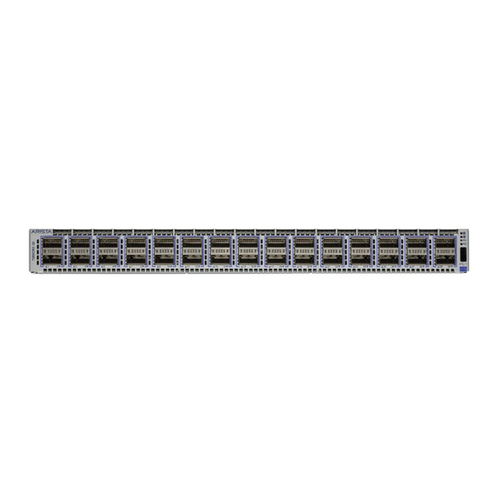
Appendix C Front Panel This appendix displays the front panel of all switches covered by this guide. Figure 27: DCS-7280CR2A-30, DCS-7280CR2K-30, and DCS-7280CR2M-30 1 System status LED 3 Power supply 1 status LED 2 Fan tray status LED 4 Power supply 2 status LED... -
Page 41: Appendix D: Rear Panel
Appendix D Rear Panel All switches covered by this guide use the rear panel shown below. Depending on the power supply module installed, the appearance could be different from the one shown. Figure 28: Rear Panel 1 Power Supply Module 1 4 Fan Module 2 7 Fan Module 5 2 Management Ports... -
Page 43: Appendix E: Maintenance And Field Replacement
All slots must be filled or covered with a blank for operation (even though power supply or fans may not be functional). • Before you begin, refer to the Arista Networks document Safety Information and Translated Safety Warnings available at: https://www.arista.com/en/support/product-documentation. Note: Descriptions for the removal and replacement of power supplies and fans are for a representative power supply or fan. -
Page 44: Installing A Power Supply
(Figure 29: Remove Power Supply). 3. Push the power supply release lever and remove the power supply Figure 29: Remove Power Supply E.2.2 Installing a Power Supply You must make space for installing the power supply by removing an existing one (Removing a Power Supply). -
Page 45: Fan Modules
Maintenance and Field Replacement Note: The Power Supply status LED should be a steady green for normal operation. 6. Verify the new power supply operation by issuing the show environment power command. switch#show environment power The output of the command will list the power supplies in operation and should include the one you replaced. - Page 46 2. Slide the new fan module into the switch until the module is fully seated and the release lever snaps into place (Installing a Fan Module). Figure 32: Inserting the Fan Module Note: The fan module status LED should be a steady green for normal operation. 3.
-
Page 47: Appendix F: Regulatory Model Numbers
Appendix F Regulatory Model Numbers This appendix lists the Regulatory Model Numbers (RMNs), where applicable, for the product models for the switches described in this document. Table 10: Regulatory Model Numbers and Product Numbers Regulatory Model Number (RMN) Product Number(s) AN1620 DCS-7280CR2A-30, DCS-7280CR2K-30 AN1711... -
Page 49: Appendix G: Taiwan Rohs Information
Appendix G Taiwan RoHS Information This appendix provides Taiwan RoHS information for switches covered by this guide. For Taiwan BSMI RoHS Table, go to https://www.arista.com/assets/data/pdf/AristaBSMIRoHS.pdf.
Need help?
Do you have a question about the 7280CR2 30 Series and is the answer not in the manual?
Questions and answers