
Subscribe to Our Youtube Channel
Related Manuals for Arista DCS-7010T-48


Summary of Contents for Arista DCS-7010T-48
-
Page 1: Quick Start Guide
Quick Start Guide 7010 Series 1 RU Data Center Switches DCS-7010T-48 DCS-7010T-48-DC Arista Networks www.arista.com PDOC-00061-02... - Page 2 © Copyright 2014 Arista Networks, Inc. The information contained herein is subject to change without notice. Arista Networks and the Arista logo are trademarks of Arista Networks, Inc in the United States and other countries. Other product or service names...
-
Page 3: Chapter 1 Overview
Important! Ultimate disposal of this product should be in accordance with all applicable laws and regulations. Safety Information Refer to the Arista Networks document Safety Information and Translated Safety Warnings available at: http://www.arista.com/support/docs/eos 7010 Series 1 RU Quick Start Guide... -
Page 4: Obtaining Technical Assistance
Chapter 1: Overview Obtaining Technical Assistance Any customer, partner, reseller or distributor holding a valid Arista Service Contract can obtain technical support in any of the following ways: • Email: support@arista.com. This is the easiest way to create a new service request. -
Page 5: Chapter 2 Preparation
Chapter 2: Preparation Chapter 2 Preparation Site Selection The following criteria should be considered when selecting a site to install the switch: • Temperature and Ventilation: For proper ventilation, install the switch where there is ample airflow to the front and back of the switch. The ambient temperature should not go below 0° or exceed 40° C. Important! To prevent the switch from overheating, do not operate it in an area where the ambient temperature exceeds 40°C (104°F). -
Page 6: Tools Required For Installation
Minimize handling of assemblies and components. • Keep replacement parts in their original static-free packaging. • Remove all plastic, foam, vinyl, paper, and other static-generating materials from the work area. • Use tools that do not create ESD. Arista Networks Copyright 2014... -
Page 7: Chapter 3 Mounting The Switch
Important! The rack mounting procedure is identical for all switches covered by this guide. Illustrations in this chapter depict the mounting of a DCS-7010T-48 switch. The switch can be mounted in a rack or operated from a flat surface, such as a table. - Page 8 Figure 5 displays the attachment of the rubber pads to the bottom of the switch. Figure 5: Attaching Rubber Pads to Bottom of Switch Arista Networks Copyright 2014...
-
Page 9: Chapter 4 Powering The Switch
Power down the Switch: Remove all power cords and wires from the power supplies. Important! This equipment must be grounded. Never defeat the ground conductor. Important! This unit requires overcurrent protection. Cabling the AC Power Supply (DCS-7010T-48) 4.1.1 Grounding the Switch After mounting the switch into the rack, connect the switch to the data center ground. - Page 10 Chapter 4: Powering the Switch Cabling the DC Power Supply (DCS-7010T-48-DC) Figure 7 displays the location of the earth grounding pad and the DC input terminals. Figure 7: DC Input Terminals and DC Grounding Pad Figure 8 displays DC power terminals on the left side of the rear panel with the terminal cover in place (left illustration) and with the terminal cover removed (right illustration).
-
Page 11: Chapter 5 Connecting Serial And Management Cables
Chapter 5 Connecting Serial and Management Cables The front panel contains the console, management, and USB ports. Figure 9 displays the ports on the DCS-7010T-48 switch. Appendix D displays the front panel of all switches covered by this guide. Figure 9: Front Panel Ports Connect the front panel ports as follows: •... -
Page 12: Chapter 6 Configuring The Switch
Chapter 6: Configuring the Switch Chapter 6 Configuring the Switch Arista switches ship from the factory in Zero Touch Provisioning (ZTP) mode. ZTP configures the switch without user intervention by downloading a startup configuration file or a boot script from a location specified by a DHCP server. -
Page 13: Appendix A Fan Module Orientation
Appendix A Fan Module Orientation Important! The procedure for changing the fan module orientation is identical for all switches covered by this guide. Illustrations in this appendix depict a DCS-7010T-48 switch. The fan module orientation determines the direction of air flowing through the switch. -
Page 14: Appendix B Status Indicators
Front panel LEDs are located on the right side of the front panel and display system, fan, and power supply status. Appendix D displays the front panels of all switches covered by this guide. Figure 11 displays the DCS-7010T-48 front panel LEDs. Figure 11: System Status Indicators Table 2: Switch Indicators LED States LED Name LED State... -
Page 15: Port Indicators
Port Indicators Port LEDs, located in the vicinity of their corresponding ports, provide link and operational status. Figure 12 displays the Port LED location on the DCS-7010T-48 switch. Appendix D displays the port LED locations of all switches covered by this guide. - Page 16 Table 4: Fan Status LED States LED State Status The fan module is inserted but not receiving power – it may not be properly seated. Green The fan is operating normally. The fan has failed. Flashing Green The switch is booting. Arista Networks Copyright 2014...
-
Page 17: Appendix C Parts List
Table 5: Switch Cables (AC Power Supply) Quantity Description Power cables: IEC-320/C13-C14, 10 A, 250 V Warning! All provided power cables are for use only with Arista products. 警告 すべての電源コードは提供する製品で使用するためだけを目的としている。 電源コードの他の製品での使用の禁止 Arista が提供するすべての電源コードは、Arista の製品でのみ使用してください。 7010 Series 1 RU Quick Start Guide... -
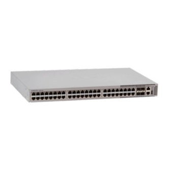
Page 18: Appendix D Front Panel
Appendix D: Front Panel Appendix D Front Panel This appendix displays the front panel of all switches covered by this guide. DCS-7010T-48 Figure 16: DCS-7010T-48 Front Panel DCS-7010T-48-DC Figure 17: DCS-7010T-48-DC Front Panel Arista Networks Copyright 2014... -
Page 19: Appendix E Rear Panel
Appendix E: Rear Panel Appendix E Rear Panel This appendix displays the rear panel of all switches covered by this guide. DCS-7010T-48 Figure 18: DCS-7010T-48 Rear Panel DCS-7010T-48-DC Figure 19: DCS-7010T-48-DC Rear Panel 7010 Series 1 RU Quick Start Guide... - Page 20 Appendix E: Rear Panel Arista Networks Copyright 2014...
Need help?
Do you have a question about the DCS-7010T-48 and is the answer not in the manual?
Questions and answers