
Related Manuals for Mitsubishi Electric FR-XC-18.5K-PWM


Summary of Contents for Mitsubishi Electric FR-XC-18.5K-PWM
- Page 1 INVERTER INSTRUCTION MANUAL Multifunction regeneration converter FR-XC-7.5K to 55K FR-XC-18.5K-PWM to 55K-PWM FR-XC-H7.5K to H55K FR-XC-H18.5K-PWM to H55K-PWM OUTLINE INSTALLATION AND WIRING PARAMETERS PROTECTIVE FUNCTIONS PRECAUTIONS FOR MAINTENANCE AND INSPECTION SPECIFICATIONS...
- Page 2 Thank you for choosing this Mitsubishi Electric multifunction regeneration converter. This Instruction Manual provides handling information and precautions for use of the this product. Incorrect handling might cause an unexpected fault. Before using this product, always read this Instruction Manual carefully to ensure proper use of this product.
- Page 3 WARNING Usage Any person must stay away from the equipment after using the retry function as the equipment will restart suddenly after output shutoff of this product. Be sure to turn OFF the start (STF/STR) signal input to the inverter before clearing the fault in the product as the inverter will restart a motor suddenly after a fault clear.
-
Page 4: Table Of Contents
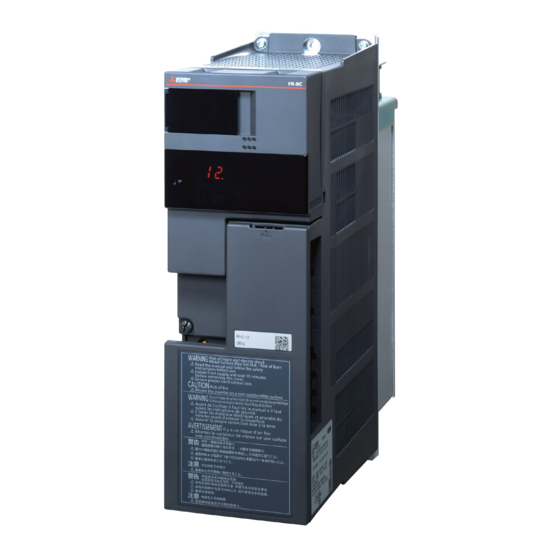
CONTENTS 1 OUTLINE Pre-operation instructions 1.1.1 Features of FR-XC series converters .......................8 1.1.2 Function selection switch assembly (SW2) ....................10 1.1.3 Product checking and parts identification .......................10 1.1.4 Harmonic suppression guidelines in Japan ....................11 Component names FR-XC series converter and peripheral devices Precautions for selecting peripheral devices 1.4.1 Techniques and measures for electromagnetic compatibility (EMC)..............17... -
Page 5: Table Of Contents
2.8.1 Terminal connection diagram ......................... 57 2.8.2 Wiring (common bus regeneration mode with harmonic suppression disabled) ..........60 2.8.3 Wiring (power regeneration mode)......................... 62 2.8.4 Wiring (common bus regeneration mode with harmonic suppression enabled)..........64 2.8.5 When using separate power supplies for the control circuit and the main circuit........... 65 Earthing (Grounding) precautions 2.10 Connection of the converter and the multiple inverters 2.10.1... -
Page 6: Table Of Contents
3.5.16 Reset selection / disconnected PU detection / PU stop selection (Pr.75) ............100 3.5.17 Parameter write disable selection (Pr.77).....................101 3.5.18 Current control (Pr.82 and Pr.83) .........................102 3.5.19 Wiring and configuration of PU connector ....................103 3.5.20 Initial settings and specifications of RS-485 communication (Pr.117 to Pr.124) ..........104 3.5.21 Mitsubishi inverter protocol (computer link communication) .................105 3.5.22... -
Page 7: Table Of Contents
6.1.2 FR-XC-[ ]K-PWM............................158 6.1.3 Combination matrix of FR-XCL and FR-XC(-PWM) ..................160 6.1.4 Combination matrix of FR-XCB and FR-XC(-PWM)..................160 Common specifications Outline dimension drawings 6.3.1 Multifunction regeneration converter (FR-XC (-PWM))............................162 6.3.2 Dedicated stand-alone reactor (FR-XCL)..................... 165 6.3.3 Dedicated box-type reactor (FR-XCB) ...................... -
Page 8: Outline
OUTLINE This chapter explains the outline of this product. Always read the instructions before use. 1.1 Pre-operation instructions ............8 1.2 Component names..............14 1.3 FR-XC series converter and peripheral devices ....16 1.4 Precautions for selecting peripheral devices ......17 <Abbreviations> FR-XC series converter....Multifunction regeneration converter (FR-XC or FR-XC-PWM converter) PU ........... -
Page 9: Pre-Operation Instructions
Pre-operation instructions Pre-operation instructions Incorrect handling may cause the equipment to operate improperly or reduce its life considerably. Also, incorrect handling may damage the FR-XC series converter and the inverter. Please handle the unit properly in accordance with the information on each section as well as the precautions and instructions of the Instruction Manual. - Page 10 • Note that the applicable inverter capacity and motor current are different depending on the harmonic suppression function condition of the FR-XC-(H)22K or FR-XC-(H)30K converter. (Refer to page 156.) • Power supply harmonic suppression effect Example of the FR-XC-18.5K-PWM Condition: Load = 100% Power factor = 0.99 or more [Harmonic suppression disabled] [Harmonic suppression enabled]...
-
Page 11: Function Selection Switch Assembly (Sw2)
Pre-operation instructions 1.1.2 Function selection switch assembly (SW2) The function can be changed by the function selection switches. Switch Function Common bus regeneration mode Power regeneration mode For manufacturer setting. (Do not change from ON) Surrounding air temperature of 50°C rating Surrounding air temperature of 40°C rating For manufacturer setting. -
Page 12: Harmonic Suppression Guidelines In Japan
Pre-operation instructions Dedicated box-type reactor (option) model FR-XCB- Symbol Voltage class Symbol Circuit board coating Reactor capacity None 200 V class None Without Capacity (kW) 400 V class With How to read the SERIAL number Rating plate example The SERIAL consists of one symbol, two characters indicating the ... - Page 13 Pre-operation instructions Application of the specific consumer guidelines Install, add or renew equipment Calculation of equivalent capacity total Equal to or less than reference capacity Equivalent capacity total Above reference capacity Calculation of outgoing harmonic current More than upper limit Not more than harmonic current upper limit?
- Page 14 Pre-operation instructions • Rated capacities and outgoing harmonic currents of inverter-driven motors Fundamental Fundamental Outgoing harmonic current converted from 6.6 kV (mA) wave current wave Applicable Rated (No reactor, 100% operation ratio) current motor capacity converted (kW) (kVA) 200 V 400 V from 6.6 kV 11th 13th...
-
Page 15: Component Names
Component names Component names Component names are shown below. 30K converters or lower Refer Symbol Name Description to page Remove it for installing a communication option, wiring the control circuit Control circuit terminal block cover terminals, or changing the SW2 switches. Communication operation status Check the state (ON/blinking) of the communication operation status ⎯... - Page 16 Component names 37K converters or higher Refer Symbol Name Description to page Remove it for installing a communication option, wiring the control circuit Control circuit terminal block cover terminals, or changing the SW2 switches. Communication operation status Check the state (ON/blinking) of the communication operation status inspection port indicators on the communication option (FR-A8NC) when the option is ⎯...
-
Page 17: Fr-Xc Series Converter And Peripheral Devices
FR-XC series converter and peripheral devices FR-XC series converter and peripheral devices <Example for the common bus regeneration mode> Three-phase AC power supply Use power supply within the permissible specifications of the converter. Molded case circuit breaker (MCCB) or earth leakage circuit breaker (ELB) and fuse The breaker must be selected carefully since an inrush current flows in the converter at power ON. -
Page 18: Precautions For Selecting Peripheral Devices
Precautions for selecting peripheral devices Precautions for selecting peripheral devices 1.4.1 Techniques and measures for electromagnetic compatibility (EMC) Some electromagnetic noises enter the converter to cause the converter malfunction, and others are radiated by the converter to cause the peripheral devices to malfunction. (The former is called electromagnetic susceptibility (EMS) problem, the latter is called electromagnetic interference (EMI) problem, and both is called electromagnetic compatibility (EMC) problem.) Though the FR-XC series converter is designed to be immune to noises, it requires the following basic measures and EMS measures as it handles low-level signals. - Page 19 Precautions for selecting peripheral devices Noise Measure propagation path When devices that handle low-level signals and are liable to malfunction due to electromagnetic noises, e.g. instruments, receivers and sensors, are contained in the enclosure that contains the converter or when their signal cables are run near the converter, the devices may malfunction due to by air-propagated electromagnetic noises.
-
Page 20: Peripheral Device List
S-T35 S-T35 FR-XC-15K 125 A 125 A S-T50 S-T50 Harmonic suppression 175 A 175 A S-T65 S-T80 disabled FR-XC-22K FR-XC-18.5K-PWM Harmonic suppression 125 A 125 A S-T50 S-T50 enabled Harmonic suppression 225 A 225 A S-T100 S-T100 disabled FR-XC-30K FR-XC-22K-PWM... - Page 21 Molded case circuit breaker (MCCB)/ converter model earth leakage circuit breaker (ELB) (NF, NV type) FR-XC-7.5K 50 A FR-XC-11K 60 A FR-XC-15K 75 A FR-XC-22K 125 A FR-XC-18.5K-PWM FR-XC-30K 175 A FR-XC-22K-PWM FR-XC-37K 200 A FR-XC-37K-PWM FR-XC-55K 250 A FR-XC-55K-PWM OUTLINE...
- Page 22 Precautions for selecting peripheral devices • 400 V class FR-XC series Molded case circuit breaker (MCCB)/ converter model earth leakage circuit breaker (ELB) (NF, NV type) FR-XC-H7.5K 30 A FR-XC-H11K 30 A FR-XC-H15K 40 A FR-XC-H22K 75 A FR-XC-H18.5K-PWM FR-XC-H30K 100 A FR-XC-H22K-PWM FR-XC-H37K...
- Page 23 — FR-XC-11K 6.9 URD 30 TTF 0160 — FR-XC-15K 6.9 URD 30 TTF 0200 — FR-XC-22K 6.9 URD 30 TTF 0315 — FR-XC-18.5K-PWM FR-XC-30K 6.9 URD 30 TTF 0400 — FR-XC-22K-PWM FR-XC-37K 6.9 URD 30 TTF 0500 — FR-XC-37K-PWM FR-XC-55K 6.9 URD 31 TTF 0700...
-
Page 24: Selecting The Rated Sensitivity Current For The Earth Leakage Circuit Breaker
Precautions for selecting peripheral devices 1.4.3 Selecting the rated sensitivity current for the earth leakage circuit breaker To install the earth leakage circuit breaker on the inverter circuit, select its rated sensitivity current as follows. • Breaker designed for harmonic and surge suppression Rated sensitivity current Ig1, lg2, lg3: Leakage currents in wire path during I∆n ≥... - Page 25 Precautions for selecting peripheral devices NOTE • Install the earth leakage circuit breaker (ELB) on the input side of the converter. • In the connection earthed-neutral system, the sensitivity current is blunt against a ground fault in the inverter output side. Earthing (Grounding) must conform to the requirements of national and local safety regulations and electrical codes.
-
Page 26: Installation And Wiring
INSTALLATION AND WIRING This chapter explains the installation and the wiring of this product. Always read the instructions before use. 2.1 Removal and reinstallation of the converter covers .....26 2.2 Removal and reinstallation of the FR-XCB reactor cover ..28 2.3 Installation of the converter and enclosure design....29 2.4 Installation of peripheral devices ..........36... -
Page 27: Removal And Reinstallation Of The Converter Covers
Removal and reinstallation of the converter covers Removal and reinstallation of the converter covers 2.1.1 30K converters or lower Main circuit terminal block cover • To remove the cover, hold and pull out the upper part of • The hooks on the lower end of the cover snap out of the cover. -
Page 28: K Converters Or Higher
Removal and reinstallation of the converter covers 2.1.2 37K converters or higher Main circuit terminal block cover • When the mounting screws are removed, the main circuit terminal block cover can be removed. To reinstall the cover, insert the hooks into the slots on the converter and push the cover to snap it into place. Control circuit terminal block cover •... -
Page 29: Removal And Reinstallation Of The Fr-Xcb Reactor Cover
Removal and reinstallation of the FR-XCB reactor cover Removal and reinstallation of the FR-XCB reactor cover Removal • Loosen the mounting screws of the cover. • Pull out the cover to remove it. ●FR-XCB-(H)18.5K, 22K Cover Cover ●FR-XCB-(H)37K or higher Cover Cover ... -
Page 30: Installation Of The Converter And Enclosure Design
Installation of the converter and enclosure design Installation of the converter and enclosure design When designing or manufacturing an enclosure, determine the structure, size, and device layout of the enclosure by fully considering the conditions such as heat generation of the contained devices and the operating environment. The multifunction regeneration converter unit uses many semiconductor devices. - Page 31 Installation of the converter and enclosure design Humidity Operate the multifunction regeneration converter within the ambient air humidity of usually 45 to 90% (up to 95% with circuit board coating). Too high humidity will pose problems of reduced insulation and metal corrosion. On the other hand, too low humidity may cause a spatial electrical breakdown.
-
Page 32: Cooling System Types For Converter Enclosure
Installation of the converter and enclosure design Vibration, impact The vibration resistance of the multifunction regeneration converter is up to 5.9 m/s at 10 to 55 Hz frequency and 1 mm amplitude for the directions of X, Y, Z axes. Applying vibration and impacts for a long time may loosen the structures and cause poor contacts of connectors, even if those vibration and impacts are within the specified values. -
Page 33: Converter Installation
Installation of the converter and enclosure design 2.3.3 Converter installation Converter placement FR-XC-(H)22K, (H)30K FR-XC-(H)18.5K-PWM, (H)22K-PWM FR-XC-(H)37K, (H)55K FR-XC-(H)7.5K, (H)11K, (H)15K FR-XC-(H)37K-PWM, (H)55K-PWM • For the models up to 30K converters or lower, cut the enclosure according to the dimensions shown on page •... - Page 34 Installation of the converter and enclosure design Arrangement of multiple converter/inverter units When multiple converter/inverter units are placed in the same enclosure, generally arrange them horizontally as shown in the figure (a). When it is inevitable to arrange Converter Inverter Inverter Inverter them vertically to minimize space, take such measures as...
-
Page 35: Protruding The Heat Sink Through A Panel
Installation of the converter and enclosure design 2.3.4 Protruding the heat sink through a panel When encasing the multifunction regeneration converter to an enclosure, the heat generated in the enclosure can be greatly reduced by protruding the heat sink of the multifunction regeneration converter. (The 30K converters or lower are designed to be installed in an enclosure with its heatsink protruded through the panel.) When installing the multifunction regeneration converter in a compact enclosure, etc., this installation method is recommended. - Page 36 Installation of the converter and enclosure design Mount point change of installation frame from the rear to the front The upper and lower installation frames are attached on the multifunction regeneration converter (one for each position). Change the mount point of the upper and lower installation frames from the rear to the front as shown in the figure. When reattaching the installation frames, make sure that the installation orientation is correct.
-
Page 37: Installation Of Peripheral Devices
Installation of peripheral devices Installation of peripheral devices 2.4.1 Installation of reactor (FR-XCL) Clearances Because the reactor generate heat, leave sufficient space around them. 10 cm or more 5 cm or more 5 cm or more Installation place Install the reactor on nonflammable material. Installing it directly on flammable material will cause a fire. Surrounding environment Avoid places where the equipment is subjected to oil mist, flammable gases, fluff, dust, dirt, etc. -
Page 38: Installation Of Box-Type Reactor (Fr-Xcb)
Installation of peripheral devices 2.4.2 Installation of box-type reactor (FR-XCB) Clearances 10 cm or more 5 cm or more 5 cm or more 10 cm or more Installation place Install the reactor on nonflammable material. Installing it directly on flammable material will cause a fire. Surrounding environment Avoid places where the equipment is subjected to oil mist, flammable gases, fluff, dust, dirt, etc. -
Page 39: Connection Of The Converter And The Inverter
Connection of the converter and the inverter Connection of the converter and the inverter 2.5.1 Inverter selection Connectable inverter models depend on the operation mode of the FR-XC series converter, the common bus regeneration mode or the power regeneration mode. Common bus regeneration mode •... - Page 40 FR-HAL-[]K 18.5 ⎯ ⎯ ⎯ FR-XC-15K × × × × Quantity FR-HAL-[]K FR-XC-22K ⎯ ⎯ ⎯ ⎯ ⎯ × × FR-XC-18.5K-PWM Quantity FR-XC-30K FR-HAL-[]K ⎯ ⎯ ⎯ ⎯ ⎯ ⎯ × FR-XC-22K-PWM Quantity FR-XC-37K FR-HAL-[]K ⎯ ⎯ ⎯ ⎯ ⎯...
-
Page 41: Switching Between The Common Bus Regeneration Mode And The Power Regeneration Mode
Connection of the converter and the inverter 2.5.2 Switching between the common bus regeneration mode and the power regeneration mode • Switch the converter connection mode between the common bus regeneration mode Common bus Power regeneration regeneration mode mode and the power regeneration mode by changing the position of switch 1 in the function selection switch assembly (SW2). -
Page 42: Main Circuit Terminal Specification
Main circuit terminal specification Main circuit terminal specification 2.6.1 Details on the main circuit terminals Terminal Terminal name Description symbol These terminals are used to detect the phase and voltage of the power supply, and to input R/L1, Power supply phase power to the control circuit. - Page 43 Main circuit terminal specification FR-XC-(H)22K-(H)30K FR-XC-(H)37K, (H)55K FR-XC-(H)18.5K-PWM, (H)22K-PWM FR-XC-(H)37K-PWM-(H)55K-PWM Charge lamp Charge lamp R/L1 R1/L11 S/L2 S1/L21 T/L3 R2/L12 S2/L22 T2/L32 R2/L12 S2/L22 T2/L32 Earth (ground) terminal Earth (ground) terminal INSTALLATION AND WIRING...
-
Page 44: Cable Size Of The Main Circuit Terminals And The Earth (Ground) Terminal
M5 (2.5) FR-XCL-11K FR-XCB-22K M5 (2.5) FR-XC-15K FR-XCL-15K FR-XCB-37K FR-XC-22K M6 (4.4) M10 (14.7) M8 (7.8) FR-XCL-22K FR-XCB-55K FR-XC-18.5K-PWM M6 (4.4) M8 (7.8) M6 (4.4) FR-XC-30K M4 (1.5) M4 (1.5) FR-XC-L30K FR-XC-22K-PWM FR-XC-37K M10 (14.7) M10 (14.7) FR-XCL-37K FR-XC-37K-PWM M8 (7.8) M10 (14.7) - Page 45 FR-XC-15K 1.25-4 22-5 22-6 1.25-4 14-5 FR-XCL-15K 22-6 40°C 40°C FR-XC-22K 50°C 50°C 1.25-4 38-8 38-6 1.25-4 22-6 FR-XCL-22K 38-6 FR-XC-18.5K-PWM 40°C 40°C FR-XC-30K 50°C 50°C 1.25-4 60-8 60-6 1.25-4 22-6 FR-XCL-30K 60-6 FR-XC-22K-PWM 40°C 40°C FR-XC-37K 50°C 50°C 1.25-4...
- Page 46 40°C or less and the wiring distance of 20 m or less from the power supply to the converter. For the FR-XC-22K / FR-XC-18.5K-PWM or higher, it is the gauge of a cable with the continuous maximum permissible temperature of 90°C (PVC cable).
- Page 47 R, S, T P, N R1, S1 (ground) R2, S2, T2 (ground) 50°C 50°C FR-XC-22K 1.25-4 22-8 38-6 1.25-4 22-6 FR-XCB-18.5K 22-8 22-6 FR-XC-18.5K-PWM 40°C 40°C FR-XC-30K 50°C 50°C 1.25-4 38-8 38-6 1.25-4 22-6 FR-XCB-22K 38-8 22-6 FR-XC-22K-PWM 40°C 40°C 50°C...
- Page 48 Main circuit terminal specification • 400 V class Crimp terminal Crimp terminal (for HIV cables, etc.) (for HIV cables, etc.) Model Rating Model Rating R2, S2, Earth R, S, T Earth R, S, T P, N R1, S1 (ground) R2, S2, T2 (ground) 50°C 50°C...
- Page 49 50°C 50°C FR-XC-15K 1.25-4 14-6 1.25-4 14-5 FR-XCL-15K 40°C 40°C 50°C 50°C FR-XC-22K 1.25-4 22-8 22-6 1.25-4 22-6 FR-XCL-22K 22-6 FR-XC-18.5K-PWM 40°C 40°C 50°C 50°C FR-XC-30K 1.25-4 38-8 38-6 1.25-4 22-6 FR-XCL-30K 22-6 FR-XC-22K-PWM 40°C 40°C FR-XC-37K 50°C 60-10 50°C 60-10 1.25-4...
- Page 50 40°C or less and the wiring distance of 20 m or less from the power supply to the converter. For the FR-XC-22K / FR-XC-18.5K-PWM or higher, it is the gauge of a cable with the continuous maximum permissible temperature of 90°C (PVC cable). It assumes a surrounding air temperature of 40°C or less and the wiring distance of 20 m or less from the power supply to the converter.
-
Page 51: Input Signal
Control circuit specification Control circuit specification 2.7.1 Details on the control circuit terminals indicates that terminal functions can be selected using Pr.3, Pr.4, or Pr.7 (Input terminal function selection) or Pr.11, Pr.12, or Pr.16 (Output terminal function selection). (Refer to page page 89.) -
Page 52: Control Logic Switchover
Control circuit specification Power supply for fan Terminal Type Terminal name Terminal function description symbol Reactor fan power Power supply terminal for the fan on the FR-XCB reactor. supply Connect it to terminal FAN1 on the reactor. Reactor fan power Common terminal for terminal FAN. - Page 53 Control circuit specification Sink logic and source logic • In the sink logic, a signal switches ON when a current flows from the corresponding signal input terminal. Terminal SD is common to the contact input signals. Terminal SE is common to the open collector output signals. •...
-
Page 54: Control Circuit Terminal Layout
Control circuit specification 2.7.3 Control circuit terminal layout Wiring method • Wire insertion Use crimp terminals and stripped wire for the control circuit wiring. For single wire, the stripped wire can be used without crimp terminal. Connect the end of wires (crimp terminal or stranded wire) to the terminal block. (1) Strip the signal wires as shown below. - Page 55 Control circuit specification NICHIFU Co., Ltd. Wire gauge Blade terminal part Insulation cap Crimping tool part No. model No. 0.3 to 0.75 BT 0.75-11 VC 0.75 NH 69 (3) Insert each wire into the terminal. When using single wire or stranded wires without a crimp terminal, push the open/ close button all the way down with a flathead screwdriver, and insert the wire.
-
Page 56: Wiring Precautions
Control circuit specification NOTE • Pulling out the wire forcefully without pushing the open/close button all the way down may damage the terminal block. • Use a small flathead screwdriver (tip thickness: 0.4 mm / tip width: 2.5 mm). If a flathead screwdriver with a narrow tip is used, terminal block may be damaged. Commercially available product (as of January 2017). -
Page 57: Details On The Control Circuit Terminals On The Fr-Xcb
Control circuit specification 2.7.5 Details on the control circuit terminals on the FR-XCB Power supply for fan Terminal Type Terminal name Terminal function description symbol Reactor fan power FAN1 Power input terminal for the fan on the reactor. Connect it to terminal FAN on the converter. input Fan power input Common terminal for terminal FAN1. -
Page 58: Wiring
Wiring Wiring • Incorrect wiring will cause a fault indication, failure, or damage of the multifunction regeneration converter. • Refer to the Instruction Manual of each inverter for the wiring of the inverter. Special attention must be paid to the wiring length and cable size. - Page 59 Wiring Power regeneration mode Inverter ∗4 FR-HAL MCCB MC R/L1 S/L2 Power supply T/L3 R1/L11 FR-XC ∗7 MCCB S1/L21 Fuse FR-XCL ∗2 ∗2∗9 DC reactor ∗8 Fuse R/L1 R2/L12 R2/L12 ∗1 (FR-HEL)∗5 ∗8 S/L2 S2/L22 S2/L22 Fuse ∗8 Fuse T/L3 T2/L32 T2/L32 Earth (ground)
- Page 60 Wiring Common bus regeneration mode with harmonic suppression enabled Inverter ∗1 R/L1 FR-XC S/L2 T/L3 ∗6 FR-XCB ∗3∗8 R1/L11 MCCB ∗7 Fuse R/L1 R2/L12 R2/L12 S1/L21 Junction terminal ∗7 Fuse S/L2 S2/L22 S2/L22 Power Fuse supply ∗7 Fuse T/L3 T2/L32 T2/L32 ∗2 Fuse...
-
Page 61: Wiring (Common Bus Regeneration Mode With Harmonic Suppression Disabled)
Wiring 2.8.2 Wiring (common bus regeneration mode with harmonic suppression disabled) Wiring between the power supply and the reactor • Cable gauge differs by the capacity. Select an appropriate cable by referring to page 43 to perform wiring. Dedicated reactor MCCB R2/L12 R/L1... - Page 62 Wiring Wiring between the power supply and the converter Supply power to the power detecting terminals (R/L1, S/L2, and T/L3) separately from the main circuit wiring. Multifunction regeneration Dedicated reactor converter R2/L12 R/L1 Power S2/L22 S/L2 supply T2/L32 T/L3 R/L1 S/L2 T/L3 R1/L11...
-
Page 63: Wiring (Power Regeneration Mode)
Wiring 2.8.3 Wiring (power regeneration mode) Wiring between the power supply and the reactor • Cable gauge differs by the capacity. Select an appropriate cable by referring to page 43 to perform wiring. AC reactor MCCB (FR-HAL) ∗1 ∗1 R/L1 S/L2 Power To inverter... - Page 64 Wiring Wiring between the power supply and the converter Supply power to the power detecting terminals (R/L1, S/L2, and T/L3) separately from the main circuit wiring. AC reactor (FR-HAL) Power To the inverter supply FR-XC Dedicated reactor MCCB (FR-XCL) R/L1 R2/L12 R2/L12 S/L2...
-
Page 65: Wiring (Common Bus Regeneration Mode With Harmonic Suppression Enabled)
Wiring 2.8.4 Wiring (common bus regeneration mode with harmonic suppression enabled) Wiring between the power supply and the reactor • Cable gauge differs by the capacity. Select an appropriate cable by referring to page 43 to perform wiring. Dedicated reactor MCCB R2/L12 R/L1... -
Page 66: When Using Separate Power Supplies For The Control Circuit And The Main Circuit
Wiring Wiring between the power supply and the converter Supply power to the power detecting terminals (R/L1, S/L2, and T/L3) separately from the main circuit wiring. Multifunction regeneration Dedicated reactor converter R2/L12 R/L1 Power S2/L22 S/L2 supply T2/L32 T/L3 R/L1 S/L2 T/L3 R1/L11... -
Page 67: Earthing (Grounding) Precautions
Earthing (Grounding) precautions Earthing (Grounding) precautions • Always earth (ground) the multifunction regeneration converter and the dedicated reactor FR-XCL or FR-XCB. Purpose of earthing (grounding) Generally, an electrical apparatus has an earth (ground) terminal, which must be connected to the ground before use. An electrical circuit is usually insulated by an insulating material and encased. -
Page 68: Connection Of The Converter And The Multiple Inverters
Connection of the converter and the multiple inverters Example of earthing (grounding) Dedicated reactor Power FR-XC series Inverter Motor supply converter box-type reactor : Earthing (grounding) cable Symbol Description Make the separate earth (ground) connection for the converter, inverter, and reactor wherever possible. The earthing (grounding) cable should be as close as possible to the power cables, and all these cables should be in parallel. - Page 69 Connection of the converter and the multiple inverters Wiring examples In the following examples, six inverters (two FR-A820-00167(2.2K) inverters, two FR-A820-00105(1.5K) inverters, and two FR-A820-00077(0.75K) inverters) are connected to the FR-XC-11K converter. • Main circuit wiring example Junction terminal 1 1st inverter Fuse 1st inverter...
- Page 70 Connection of the converter and the multiple inverters • Control circuit wiring example 1st inverter FR-A820 FR-XC -00167 (2.2K) 2nd inverter FR-A820 -00167 (2.2K) 3rd inverter FR-A820 • For the control circuit wiring, use shielded or twisted wires, and -00105 separate the wire from the main circuit and high-voltage circuits.
-
Page 71: Pu Installation On Converter
PU installation on converter 2.11 PU installation on converter • When the PU (inverter operation panel or optional parameter unit) is installed on the multifunction regeneration converter, the setting of converter parameters is possible by using the PU. Use the option FR-CB2[ ] or the following connector and cable available on the market. (To install the operation panel, the optional connector (FR-ADP) is also required.) Securely insert one end of connection cable into the PU connector on the converter and the other end into the connection connector on the parameter unit or the FR-ADP attached on the operation panel along the guides until the stoppers are... -
Page 72: Communication Operation
Communication operation 2.12 Communication operation Using the PU connector enables communication operation from a personal computer, etc. When the PU connector is used for connection between the converter and a personal, FA, or other computer with a communication cable, a user program can run to monitor the converter or read and write parameters. -
Page 73: Before Powering And Starting Operation
Before powering and starting operation 2.13 Before powering and starting operation 2.13.1 Installation Check the following points before powering and starting operation of the converter. Make sure that the converter is installed in a proper location and manner. (Refer to page 29.) •... -
Page 74: Digital Characters And Their Corresponding Printed Equivalents
Digital characters and their corresponding printed equivalents 2.14 Digital characters and their corresponding printed equivalents Digital characters displayed on the 7-segment LED display are as follows. Printed Digital Printed Digital Printed Digital INSTALLATION AND WIRING... - Page 75 MEMO...
-
Page 76: Parameters
PARAMETERS This chapter explains the parameters in this product. Always read the instructions before use. 3.1 Operation panel (FR-DU08) ............76 3.2 Monitoring the converter status ..........79 3.3 Parameter unit (FR-PU07) / Parameter unit with battery pack (FR-PU07BB(-L)) ..............80 3.4 Parameter list ................84 3.5 Parameter details ..............86... -
Page 77: Operation Panel (Fr-Du08)
Operation panel (FR-DU08) Operation panel (FR-DU08) 3.1.1 Components of the operation panel Installing the inverter operation panel (FR-DU08) on the multifunction regeneration converter allows to set the converter parameters and monitor the converter status. Component Name Description Not available for the FR-XC(-PWM) converter. MON: ON when the operation panel is in the monitor mode. -
Page 78: Basic Operation Of The Operation Panel (Factory Setting)
Operation panel (FR-DU08) 3.1.2 Basic operation of the operation panel (factory setting) Second screen Third screen ∗1 ∗1 (Input voltage monitoring) (Bus voltage monitoring) ∗1 First screen (Input current monitoring) (First priority monitor screen) The present setting displayed. Alternating (Example) Parameter write is complete. - Page 79 Operation panel (FR-DU08) 3.1.3 Digital characters and their corresponding printed equivalents Digital characters displayed on the operation panel display are as follows. A B(b) C c D(d) E(e) F(f) G(g) I(i) J(j) K(k) L(l) M(m) N o P(p) Q(q) S(s) T(t) w X(x) Y(y) Z(z) 3.1.4 Changing the parameter setting value...
-
Page 80: Monitoring The Converter Status
Monitoring the converter status Monitoring the converter status 3.2.1 Monitoring of input voltage or bus voltage POINT POINT • Press on the operation panel in the monitor mode to switch the monitor item between input current, input voltage, and bus voltage (factory setting). Operating procedure Press during converter operation to monitor the input current. -
Page 81: Parameter Unit (Fr-Pu07) / Parameter Unit With Battery Pack (Fr-Pu07Bb(-L))
Parameter unit (FR-PU07) / Parameter unit with battery pack (FR-PU07BB(-L)) Parameter unit (FR-PU07) / Parameter unit with battery pack (FR-PU07BB(-L)) Installing the optional parameter unit (FR-PU07) / parameter unit with battery pack (FR-PU07BB(-L) ) on the multifunction ∗1 regeneration converter allows to set the converter parameters and monitor the converter status. However, the available functions in the parameter unit installed on the converter are limited compared to those in the parameter unit installed on the inverter. -
Page 82: Monitoring Function
Parameter unit (FR-PU07) / Parameter unit with battery pack (FR-PU07BB(-L)) 3.3.2 Monitoring function Indications displayed on the monitoring screen (f) Warning indication I In 10.0 (a) Main monitor (e) Unit indication (b) Phase sequence (c) Operating status (d) Operation mode indication indication indication... -
Page 83: Function Menu
Parameter unit (FR-PU07) / Parameter unit with battery pack (FR-PU07BB(-L)) 3.3.3 Function menu Press in any operation mode to call the function menu, on which you can perform various functions. NOTE • There are menus in which some functions are not available. Function menu list Function menu Description... - Page 84 Parameter unit (FR-PU07) / Parameter unit with battery pack (FR-PU07BB(-L)) 3 Pr.List 1 Setting Mode SETTING MODE 1 Appl.Grp 2 Pr.List 0∼9:Ser Pr.No. 2 Pr.List ∗1 Perform parameter copy (writing) while the 3 Set Pr.List 3 User List ∗1 SOF signal is ON. Select Oper 4 Param Copy 4 Def.Pr.List...
-
Page 85: Parameter List
Parameter list Parameter list Parameter read/write requires the operation panel (FR-DU08) or the optional parameter unit (FR-PU07 or FR- PU07BB(-L)). NOTE • indicates simple mode parameters. • The setting of parameters in highly colored cell ( ) is changeable during operation even if "1" (write disabled) is set to Pr.77 Parameter write selection. - Page 86 Parameter list Minimum Refer to Customer Name Setting range setting Initial value page setting increment Reset selection / 0 to 3, 14 to 17 disconnected PU detection / list PU stop selection 77 1, 2 Parameter write selection Voltage control proportional 0 to 1000% ∗4 gain...
-
Page 87: Parameter Details
Parameter details Parameter details 3.5.1 Showing/hiding extended parameters (Pr.0) This function restricts the parameters that are read on the PU (operation panel or parameter unit). Name Initial value Setting range Description Displays only the simple mode 9999 parameters. Simple mode selection Displays simple mode and extended parameters. -
Page 88: Input Terminal Function Selection (Pr.3, Pr.4, And Pr.7)
Parameter details 3.5.3 Input terminal function selection (Pr.3, Pr.4, and Pr.7) Use the following parameters to select or change the input terminal functions. Name Initial value (signal name) Setting range LOH terminal function LOH (Box-type reactor overheat protection) selection SOF terminal function SOF (Converter stop) 0, 3 to 5, 9999 selection... -
Page 89: Operation Selection For The Sof Signal And The Oh Signal (Pr.8 And Pr.9)
Parameter details 3.5.4 Operation selection for the SOF signal and the OH signal (Pr.8 and Pr.9) The converter operations can be changed by using Pr.8 for the SOF signal and Pr.9 for the OH signal. Initial Setting Name Description value range NO contact: Turning ON of the SOF signal stops the converter operation. -
Page 90: Output Terminal Function Selection (Pr.11, Pr.12, And Pr.16)
Parameter details 3.5.5 Output terminal function selection (Pr.11, Pr.12, and Pr.16) Use the following parameters to change the functions of the open collector output terminals and relay output terminals. Terminal Name Initial value (signal name) Setting range type RSO terminal Open RSO (During converter reset) function selection... -
Page 91: Dc Voltage Control (Pr.22, Pr.23, Pr.80, And Pr.81)
Parameter details 3.5.6 DC voltage control (Pr.22, Pr.23, Pr.80, and Pr.81) Use the following parameters to control DC voltage output from the converter with harmonic suppression enabled as commanded. Operation can be stable enough with these parameters in the initial setting, however, some adjustments may be required if voltage vibration occurs depending on the power supply condition. -
Page 92: Converter Parts Life Display (Pr.31 To Pr.33)
Parameter details 3.5.7 Converter parts life display (Pr.31 to Pr.33) The degrees of deterioration of main circuit capacitor, cooling fan and inrush current limit circuit can be diagnosed on the monitor. When a part approaches the end of its life, an alarm can be output by self diagnosis to prevent a fault. (Note that the life diagnosis of this function should be used as a guideline only, because with the exception of the main circuit capacitor, the life values are theoretical calculations.) Initial... -
Page 93: Maintenance Timer Alarm (Pr.34 And Pr.35)
Parameter details Life display of the inrush current limit circuit (Pr.32) • The life of the inrush current limit circuit (relay, contactor, and inrush resistor) is displayed in Pr.32. • The number of times the contacts of relay, contactor, and thyristor turn ON is counted down from 100% (0 time) by 1% every 1000 times. -
Page 94: Instantaneous Power Failure Detection Hold Signal (Pr.44)
Parameter details 3.5.9 Instantaneous power failure detection hold signal (Pr.44) Use this function to check the history of instantaneous power failures. Name Initial value Setting range Description Turns OFF the Instantaneous power failure Instantaneous power failure detection hold (Y16) signal. 9999 detection signal clear 9999... -
Page 95: Setting Status Display Of Function Selection Switch Assembly (Sw2)
Parameter details 3.5.10 Setting status display of function selection switch assembly (SW2) The SW2 setting status can be checked with a parameter setting Name Initial value Setting range Description 0 to 15 SW2 setting status SW2 setting status shown in decimal number (Read-only) The setting status of the partial switches 1 to 4 in the function selection switch assembly (SW2), which means the setting status of the temperature derating selection and the connection mode selection, can be checked with Pr.415. -
Page 96: Function Selection For Monitor Item Indication (Pr.46 To Pr.48, Pr.52, And Pr.896)
Parameter details 3.5.11 Function selection for monitor item indication (Pr.46 to Pr.48, Pr.52, and Pr.896) The monitor item to be displayed on the operation panel or the main monitor of the parameter unit can be selected. Name Initial value Setting range Description Set "0"... - Page 97 Parameter details Monitoring I/O terminals on the operation panel (FR-DU08) (Pr.52) • When Pr.52 = "25", the I/O terminal states can be monitored on the operation panel (FR-DU08). • When a terminal is ON, the corresponding LED segment is ON . The center LED segments are always ON. Segments corresponding to input terminals The center LED segments are always ON.
-
Page 98: Operation Selection At Instantaneous Power Failure (Pr.57)
Parameter details 3.5.12 Operation selection at instantaneous power failure (Pr.57) Use this parameter to set whether the multifunction regeneration converter restarts the operation at the power restoration after an instantaneous power failure occurs. Name Initial value Setting range Description The converter restarts operation at the power restoration from instantaneous power failure. -
Page 99: Retry Function (Pr.65, Pr.67 To Pr.69)
Parameter details 3.5.15 Retry function (Pr.65, Pr.67 to Pr.69) This function allows the converter the retry operation (automatic reset and restart) after a fault occurred. Faults which trigger the retry operation can be selected. Name Initial value Setting range Description Faults which trigger the retry operation can be Retry selection 0 to 4... - Page 100 Parameter details • When the protective function is activated after retries are attempted consecutively more than the number of times set in Pr.67, the Retry count excess fault (E.K) occurs and the converter output is shut off. (Refer to the figure of retry failure example.) •...
-
Page 101: Reset Selection / Disconnected Pu Detection / Pu Stop Selection (Pr
Parameter details 3.5.16 Reset selection / disconnected PU detection / PU stop selection (Pr.75) The reset input acceptance, disconnected PU connector detection function, and PU stop function can be selected. Name Initial value Setting range Description Reset selection / For the initial setting, reset is always disconnected PU detection / 0 to 3, 14 to 17 enabled, without disconnected PU... - Page 102 Parameter details How to restart operation stopped by using on the PU ("PS" (PU stop) warning reset method) • For the operation panel (FR-DU08) 1. Turn ON the SOF signal to stop the converter operation. 2. Press The indication "LD (PS)" on the converter is cleared (the PS warning is reset).
- Page 103 Parameter details 3.5.18 Current control (Pr.82 and Pr.83) Use this function to control current output from the converter with harmonic suppression enabled as commanded. Operation can be stable enough with these parameters in the initial setting, however, some adjustments may be required if current vibration occurs depending on the power supply condition.
-
Page 104: System Configuration
Parameter details 3.5.19 Wiring and configuration of PU connector Using the PU connector enables communication operation from a personal computer, etc. When the PU connector is connected to a personal, FA, or other computer with a communication cable, a user program can run and monitor the converter or read and write to parameters. - Page 105 Parameter details NOTE • Connection cable between converters and computer Refer to the following for the connection cable (RS-232C to RS-485 converter) between the computer with an RS-232C interface and a converter. Commercially available products (as of February 2015) Model Manufacturer Interface embedded cable DAFXIH-CAB (D-SUB25P for personal computer) /...
-
Page 106: Mitsubishi Inverter Protocol (Computer Link Communication)
Parameter details Initial Name Setting range Description value Set the time delay between data transmission to the 0 to 150 ms converter and the response. PU communication waiting 9999 The time delay is not set in this parameter but in time setting 9999 communication data. - Page 107 Parameter details Communication operation presence/absence and data format types • Data communication between the computer and converter uses ASCII codes (hexadecimal codes). • Communication operation presence/absence (with/without) and data format type (A to F) are as follows. Parameter/ Parameter Data Operation monitor Converter...
- Page 108 Parameter details • Data reading format Data a: Communication request data from the computer to the converter Number of characters Format Converter Instruction ∗4 ∗3 code check station No. ∗1 ∗2 Data c: Reply data from the converter to the computer (No data error detected) Number of characters Format Converter...
- Page 109 Parameter details Data definitions • Control code Signal name ASCII code Description Start of text (Start of data) End of text (End of data) Enquiry (Communication request) Acknowledge (No data error detected) Line feed Carriage return Negative acknowledge (Data error detected) •...
- Page 110 Parameter details • Sum check code The sum check code is 2-digit ASCII (hexadecimal) representing the lower 1 byte (8 bits) of the sum of the target data converted in ASCII character code. (Example 1) Instruction check Station No. Data code Computer →...
- Page 111 Parameter details Response time Data transmission time (Refer to the following formula.) Converter data processing time = Delay time + Data check time (Number set (It varies depending ∗3 in data × 10 (ms)) on the instruction code.) Multifunction Computer regeneration converter Time Multifunction...
- Page 112 Parameter details Retry count setting (Pr.121) • Set the permissible number of retries at data receive error occurrence. (Refer to page 109 for data receive error which enables retry.) • When the data receive errors occur consecutively and exceed the permissible number of retries set, the converter outputs the Alarm (LF) signal.
-
Page 113: Programming Instructions
Parameter details Programming instructions • When data from the computer has any error, the converter does not accept that data. Hence, in the user program, always insert a retry program for data error. • Data communication starts when the computer gives a communication request to the converter. The converter does not send any data without the computer's request. - Page 114 Parameter details Port open Communication setting Time out setting Send data processing ○Data setting ○Sum code calculation ○Data transmission Receive data waiting Receive data processing ○Data retrieval ○Screen display CAUTION Always set the communication check time interval before starting operation to prevent hazardous conditions. ...
- Page 115 Parameter details Setting items and set data After completion of parameter settings, set the instruction codes and data, then start communication from the computer to allow various types of operation control and monitoring. Number of Read/ Instruction Item Data description data digits write code...
- Page 116 Parameter details Number of Read/ Instruction data digits Item Data description write code (format) 4 digits Read H00 to H63 Refer to the instruction code list (on page 175) to read/write parameter (B and E/D) settings as required. Parameter setting For the setting of Pr.100 or later, the link parameter extended setting is 4 digits Write H80 to HE3...
- Page 117 Parameter details [Monitoring of converter status] Instruction Item Description Example code length b0: RYB (Inverter run enable) [Example 1] H43: Converter is power driving. b1: Power driving b2: Regenerative driving Converter b3: RSO (During converter reset) ∗1 status 8 bits b4: —...
- Page 118 Parameter details 3.5.22 Initial setting and specification of the CC-Link communication function (Pr.542 to Pr.544) Set the CC-Link communication details such as station number and transmission speed. Initial Name Setting range Description value Station number (CC-Link) 1 to 64 Enter the station number of the converter. ∗1 Transmission speed 0 to 4...
- Page 119 Parameter details CC-Link extended setting (Pr.544) The functions of the remote register can be extended. Refer to "I/O signal list" for details of the remote I/O signals and the remote registers. CC-Link Pr.544 setting Description version 0 (initial value) One station occupied (FR-A5NC compatible) ∗1 One station occupied One station occupied, double setting...
- Page 120 Parameter details Remote register (Refer to page 121.) ● When "One station occupied (FR-A5NC compatible)" for the CC-Link Ver. 1 is selected (Pr.544 = "0") Description Description Address Address Upper 8 bits Lower 8 bits Upper 8 bits Lower 8 bits RWwn Monitor code 2 Monitor code 1...
- Page 121 Parameter details Details of the remote I/O signals The device numbers described in this section are for the station number 1. For the station number 2 and later, the device numbers are different. (Refer to the manual of the CC-Link master module for the correspondence between device numbers and station numbers.) ●...
- Page 122 Parameter details Details of the remote register The device numbers described in this section are for the station number 1. For the station number 2 and later, the device numbers are different. (Refer to the manual of the CC-Link master module for the correspondence between device numbers and station numbers.) ●...
- Page 123 Parameter details Details of instruction code Operation control and monitoring can be performed through CC-Link communication by setting the following instruction codes and corresponding data after setting parameters. Set instruction codes using the remote register (RWw) (refer to page 121). Definitions read by instruction codes are stored in the remote register (RWr) (refer to page 121).
- Page 124 Parameter details 3.5.23 Operation at a communication error (Pr.500 to Pr.502) The converter operation at an error occurrence in the CC-Link communication can be selected. Initial Setting Name Description value range Communication error Set the waiting time from the communication error 0 to 999.8 s ∗1 execution waiting time...
- Page 125 Parameter details Operation selection at a communication error (Pr.502) The converter operation at a communication line error occurrence or at an option fault occurrence can be selected. Parameter setting • Converter operation at fault occurrence Converter Fault type Pr.502 setting Indication Fault signal operation...
- Page 126 Parameter details 3.5.25 Setting of parameter unit / operation panel (Pr.145, Pr.990, and Pr.991) Setting of the PU (parameter unit / operation panel) can be changed. Name Initial value Setting range Description Japanese English German PU display language French selection Spanish Italian Swedish...
-
Page 127: Parameter Clear / All Parameter Clear On The Operation Panel
Parameter clear / All parameter clear on the operation panel Parameter clear / All parameter clear on the operation panel POINT POINT • Set "1" to Pr.CLR Parameter clear or ALL.CL All parameter clear to initialize parameters. (Parameters cannot be cleared when Pr.77 Parameter write selection = "1".) •... -
Page 128: Parameter Copy
Copying and verifying parameters on the operation panel 3.7.1 Parameter copy • Parameter settings in a FR-XC series converter can be copied to another FR-XC series converter. Reading the parameter settings in the converter and storing them in the operation panel Operating procedure 1. -
Page 129: Parameter Verification
Copying and verifying parameters on the operation panel 3.7.2 Parameter verification • Whether the parameter settings of converters are the same or not can be checked. Operating procedure Copy the parameter settings in the verification source converter to the operation panel according to the procedure on page 127. -
Page 130: Checking Parameters Changed From Their Initial Values (Initial Value Change List)
Checking parameters changed from their initial values (initial value change list) Checking parameters changed from their initial values (initial value change list) Parameters changed from their initial values can be displayed. Operating procedure Turning ON the power of the converter The operation panel is in the monitor mode. - Page 131 MEMO...
-
Page 132: Protective Functions
PROTECTIVE FUNCTIONS This chapter explains the protective functions in this product. Always read the instructions before use. 4.1 Converter fault and indication ..........132 4.2 Reset method for the protective functions......132 4.3 List of indications ..............133 4.4 Causes and corrective actions ..........134 4.5 Check and clear of the fault history ........143... -
Page 133: Converter Fault And Indication
Converter fault and indication Converter fault and indication When a fault occurs in the converter, a protective function is automatically activated to shut off the converter output and show an indication on the PU and on the operation status 7-segment LED display of the converter. If any indication which is not shown in the list of indications (provided in a subsequent section) appears or if you have any other problem, please contact your sales representative. -
Page 134: Protective Functions
List of indications List of indications Indication on the operation status 7-segment LED Refer to Name display of the converter page ⎯ ⎯ Operation panel lock (HOLD) Error ⎯ ⎯ Write disable error (Er1) message ⎯ ⎯ Copy operation fault (rE1 to rE4) Overload signal detection Electronic thermal relay function pre-alarm PU stop... -
Page 135: Causes And Corrective Actions
Causes and corrective actions Causes and corrective actions Error message A message regarding operational troubles on the operation panel is displayed. Output is not shut off. Operation panel HOLD indication Name Operation panel lock Description Operation lock is set. Operation other than is invalid. - Page 136 Causes and corrective actions Warning Output is not shut off when a protective function is activated. Converter indication PU indication Name Overload signal detection Description Appears when the current limit function of the converter is activated. • Check that the acceleration/deceleration time set in the inverter is not too short. Check point •...
- Page 137 Causes and corrective actions Converter indication PU indication — Name Converter operation disabled Appears when the regenerative operation is not possible due to data processing in the converter such as Description during operation triggered by the SOF signal. • Check that the SOF signal is not ON. •...
- Page 138 Causes and corrective actions FR-PU07 Stedy Spd OV indication FR-PU07 Converter indication indication (Alarm Hist) FR-DU08 E.OVT indication Name Overvoltage trip If the converter's internal main circuit DC voltage reaches or exceeds the specified value, the protective Description circuit is activated to stop the outputs of the converter. The circuit may also be activated by a surge voltage produced in the power supply system.
- Page 139 Causes and corrective actions FR-PU07 Under Voltage indication FR-PU07 Converter indication indication (Alarm Hist) FR-DU08 E.UVT indication Name Undervoltage If the power supply voltage of the converter decreases, the control circuit will not perform normal functions. To Description prevent this, the output of the converter is stopped when the power supply voltage drops to about 150 VAC or lower.
- Page 140 Causes and corrective actions FR-PU07 Retry No Over indication FR-PU07 Converter indication indication (Alarm Hist) FR-DU08 E.RET indication Name Retry count excess If operation cannot be resumed properly within the number of retries set, this function stops the outputs of the converter.
- Page 141 Causes and corrective actions FR-PU07 Corrupt Memry indication FR-PU07 Converter indication indication (Alarm Hist) FR-DU08 E.PE indication Name Parameter storage device fault (control circuit board) Description The converter output is shut off if a fault occurs in the parameters stored. (EEPROM failure) Check point Check for too many number of parameter write times.
- Page 142 Causes and corrective actions FR-PU07 Fault indication FR-PU07 Converter indication indication (Alarm Hist) FR-DU08 E.MF2 indication Name Unsupported control selection Appears to stop the outputs of the multifunction regeneration converter if unsupported function is set to be Description enabled by using Pr.416 Control method selection. Check point Check the setting of Pr.416.
- Page 143 Causes and corrective actions FR-PU07 Fault 1 indication FR-PU07 Converter indication E. 1 indication (Alarm Hist) FR-DU08 indication Name Option fault The converter output is shut off when a contact failure occurs between the converter and the communication Description option. Appears when the switch for manufacturer setting on the communication option is changed.
-
Page 144: Check And Clear Of The Fault History
Check and clear of the fault history Check and clear of the fault history The operation panel stores the last eight fault records which appeared when a protective function was activated (fault history). Checking the fault history Monitoring mode Parameter setting mode Fault history mode [Operation for displaying fault history] The last eight fault records can be displayed. -
Page 145: Check First When You Have A Trouble
Check first when you have a trouble Clearing the fault history POINT POINT • Set Err.CL Fault history clear = "1" to clear the fault history. Operating procedure Turning ON the power of the converter The operation panel is in the monitor mode. Selecting the parameter setting mode Press to choose the parameter setting mode. -
Page 146: Maintenance And
PRECAUTIONS FOR MAINTENANCE AND INSPECTION This chapter explains the precautions for maintenance and inspection of this product. Always read the instructions before use. 5.1 Inspection item................146 5.2 Measurement of main circuit voltages, currents, and powers ..................152 PRECAUTIONS FOR MAINTENANCE AND INSPECTION... -
Page 147: Inspection Item
Inspection item The converter is a static unit mainly consisting of semiconductor devices. Daily inspection must be performed to prevent any fault from occurring due to the adverse effects of the operating environment, such as temperature, humidity, dust, dirt and vibration, changes in the parts with time, service life, and other factors. -
Page 148: Daily And Periodic Inspection List
Inspection item 5.1.3 Daily and periodic inspection list Inspection interval Area of Corrective action at Check by Inspection item Description inspection fault occurrence user Periodic Daily ∗2 Surrounding Check the surrounding air temperature, humidity, dirt, Improve the environment. environment corrosive gas, oil mist, etc. -
Page 149: Continuity Test
Inspection item 5.1.4 Continuity test Preparation • Disconnect the external power cables from terminals R2/L12, S2/L22, T2/L32, P/+, and N/-. • Prepare a continuity tester. (For the resistance measurement, use the 100 Ω range.) Checking method Change the polarity of the tester alternately at a semiconductor device (transistor) on an electrical path between two terminals among the converter main circuit terminals R2/L12, S2/L22, T2/L32, P/+, and N/- to check the electric continuity. -
Page 150: Replacement Of Parts
Inspection item 5.1.6 Replacement of parts The converter consists of many electronic parts such as semiconductor devices. The following parts may deteriorate with age because of their structures or physical characteristics, leading to reduced performance or fault of the converter. For preventive maintenance, the parts must be replaced periodically. The standard replacement interval of the converter parts is as follows. - Page 151 Inspection item • 37K converters or higher 1) Remove the fan cover fixing screws, and remove the fan cover. 2) Disconnect the fan connector and remove the fan block. 3) Remove the fan fixing screws, and remove the fan. Fan block Fan cover Fan connection connector...
- Page 152 Inspection item Smoothing capacitors A large-capacity aluminum electrolytic capacitor is used for smoothing in the main circuit DC section, and an aluminum electrolytic capacitor is used for stabilizing the control power in the control circuit. Their characteristics are deteriorated by the adverse effects of ripple currents, etc.
-
Page 153: Measurement Of Main Circuit Voltages, Currents, And Powers
Measurement of main circuit voltages, currents, and powers Measurement of main circuit voltages, currents, and powers • Measurement method of voltage and current at each section: When instruments for commercial frequency are used for measurement, measure the following circuits with the instruments given below. -
Page 154: Insulation Resistance Test Using Megger
Measurement of main circuit voltages, currents, and powers Remarks Item Measuring point Measuring instrument (reference measured value) Commercial power, Input voltage Across terminals R2 and S2, Moving-iron AC voltmeter within permissible AC voltage fluctuation (Refer S2 and T2, and T2 and R2 page 156.) Input current... - Page 155 MEMO...
-
Page 156: Specifications
SPECIFICATIONS This chapter explains the specifications of this product. Always read the instructions before use. Rating..................156 6.2 Common specifications ............161 6.3 Outline dimension drawings............162 SPECIFICATIONS... -
Page 157: Rating
The DC bus voltage is approx. 297 VDC at an input voltage of 200 VAC, approx. 327 VDC at 220 VAC, and approx. 342 VDC at 230 VAC. ∗5 One inverter for operation in the power regeneration mode. ∗6 Mass of the FR-XC alone. ∗7 Maximum capacity of regenerative power generated from the Mitsubishi Electric 4-pole standard motor in each axis. SPECIFICATIONS... - Page 158 The DC bus voltage is approx. 594 VDC at an input voltage of 400 VAC, approx. 653 VDC at 440 VAC, and approx. 713 VDC at 480 VAC. ∗5 One inverter for operation in the power regeneration mode. ∗6 Mass of the FR-XC alone. ∗7 Maximum capacity of regenerative power generated from the Mitsubishi Electric 4-pole standard motor in each axis. SPECIFICATIONS...
-
Page 159: Fr-Xc-[ ]K-Pwm
The DC bus voltage is approx. 297 VDC at an input voltage of 200 VAC, approx. 327 VDC at 220 VAC, and approx. 342 VDC at 230 VAC. ∗6 One inverter for operation in the power regeneration mode. ∗7 Mass of the FR-XC alone. ∗8 Maximum capacity of regenerative power generated from the Mitsubishi Electric 4-pole standard motor in each axis. SPECIFICATIONS... - Page 160 The DC bus voltage is approx. 594 VDC at an input voltage of 400 VAC, approx. 653 VDC at 440 VAC, and approx. 713 VDC at 480 VAC. ∗6 One inverter for operation in the power regeneration mode. ∗7 Mass of the FR-XC alone. ∗8 Maximum capacity of regenerative power generated from the Mitsubishi Electric 4-pole standard motor in each axis. SPECIFICATIONS...
-
Page 161: Combination Matrix Of Fr-Xcl And Fr-Xc(-Pwm)
Rating 6.1.3 Combination matrix of FR-XCL and FR-XC(-PWM) Dedicated stand- Multifunction regeneration converter alone reactor FR-XCL-(H)[ ]K FR-XC-(H)[ ]K FR-XC-(H)[ ]K-PWM ∗1 ⎯ ⎯ ⎯ 18.5 ∗1 The harmonic suppression function is pre-enabled in this model. To use the converter with the FR-XCL, change the "9999" setting of Pr.416 Control method selection to "0" (harmonic suppression disabled). (Refer to page 6.1.4... -
Page 162: Specifications
Common specifications Common specifications Input frequency range 50 to 60 Hz The following signals can be assigned to Pr.3, Pr.4, or Pr.7 (Input terminal function selection): Input signal (3) Converter stop (SOF), Converter reset (RES), External thermal relay input (OH), and Box-type reactor overheat protection (LOH). -
Page 163: Outline Dimension Drawings
Outline dimension drawings Outline dimension drawings 6.3.1 Multifunction regeneration converter (FR-XC (-PWM)) FR-XC-(H)7.5K, (H)11K φ6 hole Enclosure cut dimensions M5 screw 2-M5 screw Hole 20 13 (Unit: mm) FR-XC-(H)15K φ6 hole Enclosure cut dimensions M5 screw 2-M5 screw Hole (Unit: mm) SPECIFICATIONS... - Page 164 Outline dimension drawings FR-XC-(H)22K, (H)30K FR-XC-(H)18.5K-PWM, (H)22K-PWM 2-φ6 hole Enclosure cut dimensions M5 screw 4-M5 screw Hole 26.5 26.5 (Unit: mm) FR-XC-(H)37K, H55K FR-XC-(H)37K-PWM, H55K-PWM 4-φ20 hole 2-φ10 hole M8 screw (Unit: mm) SPECIFICATIONS...
- Page 165 Outline dimension drawings FR-XC-55K FR-XC-55K-PWM 2-φ10 hole 4-φ20 hole M8 screw (Unit: mm) SPECIFICATIONS...
-
Page 166: Dedicated Stand-Alone Reactor (Fr-Xcl)
Outline dimension drawings 6.3.2 Dedicated stand-alone reactor (FR-XCL) Check that the FR-XCL reactor that matches the converter is selected. 200 V class FR-XCL-7.5K, 11K Remove M6 screw Installation hole varnish. 55±1.5 120 max 165±2.5 D2 ± 2.5 Terminal Model Mass screw size FR-XCL-7.5K... - Page 167 Outline dimension drawings FR-XCL-15K, 22K, 30K Remove M6 screw Installation hole varnish. H2 max W1 ± 1.5 H ± 2.5 W±2.5 Terminal Model screw Mass size FR-XCL-15K 110.5 5.5 kg FR-XCL-22K 110.5 6.3 kg FR-XCL-30K 125.5 10 kg (Unit: mm) SPECIFICATIONS...
- Page 168 Outline dimension drawings FR-XCL-37K, 55K R/L1 R2/L12 S/L2 S2/L22 T/L3 T2/L32 Installation hole Remove M8 screw varnish. W1±1.5 H2 max H±5 W±2.5 Terminal Model screw Mass size FR-XCL-37K 12.0kg FR-XCL-55K 15.5kg (Unit: mm) SPECIFICATIONS...
- Page 169 Outline dimension drawings 400 V class FR-XCL-H7.5K, H11K, H15K R2/L12 S/L2 S2/L22 R/L1 T/L3 T2/L32 Installation hole M6 screw Remove varnish. 55±1.5 H2 max 165±2.5 H±2.5 Terminal Model screw Mass size FR-XCL-H7.5K 3.7kg FR-XCL-H11K 4.2kg FR-XCL-H15K 6.0kg (Unit: mm) SPECIFICATIONS...
- Page 170 Outline dimension drawings FR-XCL-H22K, H30K R/L1 R2/L12 S/L2 S2/L22 T/L3 T2/L32 Remove M6 screw varnish. 70±1.5 H2 max 240±2.5 H±2.5 Terminal Model screw Mass size FR-XCL-H22K 9.0kg FR-XCL-H30K 12.0kg (Unit: mm) SPECIFICATIONS...
- Page 171 Outline dimension drawings FR-XCL-H37K, H55K R/L1 R2/L12 S/L2 S2/L22 T/L3 T2/L32 Remove varnish. Installation hole M8 screw W1±1.5 230 max H±5 W±2.5 Terminal Model screw Mass size FR-XCL-H37K 12.0kg FR-XCL-H55K 16.0kg (Unit: mm) SPECIFICATIONS...
-
Page 172: Dedicated Box-Type Reactor (Fr-Xcb)
Outline dimension drawings 6.3.3 Dedicated box-type reactor (FR-XCB) Check that the FR-XCB reactor that matches the converter is selected. FR-XCB-(H)18.5K, (H)22K 2-φ10 hole M8 screw 4-φ25 hole 32.5 32.5 Model Mass FR-XCB-18.5K, 22K 26.0kg FR-XCB-H18.5K, H22K 26.9kg (Unit: mm) ... - Page 173 MEMO...
-
Page 174: Appendix
APPENDIX APPENDIX provides the reference information for use of this product. Refer to APPENDIX as required. Appendix 1 Major differences between FR-XC and FR-XC-PWM..174 Appendix 2 Instruction code list ............175 Appendix 3 Instructions for compliance with the EU Directives ..176 Appendix 4 Instructions for UL and cUL .........179 Appendix 5 Instructions for EAC... - Page 175 Appendix 1 Major differences between FR-XC and FR-XC-PWM Item FR-XC FR-XC-PWM FR-XC-[ ]K FR-XC-[ ]K-PWM Capacity indication in model name []: Rating of the converter with harmonic []: Rating of the converter with harmonic suppression disabled suppression enabled Capacity range (kW) 7.5, 11, 15, 22, 30, 37, 55 18.5, 22, 37, 55 Harmonic suppression disabled...
- Page 176 Appendix 2 Instruction code list ∗1 The instruction code is used to write or read parameters through RS-485 communication or CC-Link communication. (For RS-485 communication, refer to page 105. For CC-Link communication, refer to page 117.) ∗2 For Parameter copy, Parameter clear, and All parameter clear, ○ indicates the function is available, and × indicates the function is not available. ∗3 These parameters are not cleared by Parameter clear command or All parameter clear command sent through RS-485 communication or CC- Link communication.
- Page 177 CE marking. • The authorized representative in the EU The authorized representative in the EU is shown below. Name: Mitsubishi Electric Europe B.V. Address: Mitsubishi-Electric-Platz 1, 40882 Ratingen, Germany • Note We declare that this multifunction regeneration converter, when equipped with the dedicated EMC filter, conforms with the EMC Directive in industrial environments and affix the CE marking on the converter.
- Page 178 400 V class (Manufacture by: COSEL CO., LTD.) FR-XC-H22K FR-XC-H37K FR-XC-H30K FR-XC-H55K Multifunction FR-XC-H18.5K-PWM FR-XC-H37K-PWM FR-XC-H7.5K regeneration FR-XC-H15K FR-XC-H22K-PWM FR-XC-H55K-PWM FR-XC-H11K converter Harmonic suppression Harmonic suppression Disabled Enabled Disabled Enabled EMC Directive compliant FSB-30-324 FTB-80-663-L FTB-80-663-L FTB-80-355-L FTB-150-355-L FTB-150-355-L noise filter •...
- Page 179 FR-XC-11K A070URD30TTI0160 Mersen 700 V 160 A FR-XC-15K A070URD30TTI0160 Mersen 700 V 160 A FR-XC-22K A070URD30TTI0250 Mersen 700 V 250 A FR-XC-18.5K-PWM FR-XC-30K A070URD30TTI0315 Mersen 700 V 315 A FR-XC-22K-PWM FR-XC-37K A070URD30TTI0350 Mersen 700 V, 350 A FR-XC-37K-PWM FR-XC-55K A070URD30TTI0500...
- Page 180 FR-XC-11K A070URD30TTI0160 Mersen 700 V, 160 A FR-XC-15K A070URD30TTI0160 Mersen 700 V, 160 A FR-XC-22K A070URD30TTI0250 Mersen 700 V, 250 A FR-XC-18.5K-PWM FR-XC-30K A070URD30TTI0315 Mersen 700 V, 315 A FR-XC-22K-PWM FR-XC-37K A070URD30TTI0350 Mersen 700 V, 350 A FR-XC-37K-PWM FR-XC-55K A070URD30TTI0500...
- Page 181 [Fuse installation example] • Common bus regeneration mode Inverter UL listed fuses FR-XCL/ FR-XCB FR-XC for branch circuit MCCB MC protection R/L1 R2/L12 R2/L12 Power S/L2 S2/L22 S2/L22 supply T/L3 T2/L32 T2/L23 • Power regeneration mode Inverter AC reactor (FR-HAL) MCCB MC Power supply...
- Page 182 10.) • Authorized sales representative (importer) in the CU area The authorized sales representative (importer) in the CU area is shown below. Name: Mitsubishi Electric (Russia) LLC Address: 52, bld 1 Kosmodamianskaya Nab 115054, Moscow, Russia Phone: +7 (495) 721-2070...
- Page 183 Appendix 6 Restricted Use of Hazardous Substances in Electronic and Electrical Products The mark of restricted use of hazardous substances in electronic and electrical products is applied to the product as follows based on the "Management Methods for the Restriction of the Use of Hazardous Substances in Electrical and Electronic Products"...
- Page 184 WARRANTY When using this product, make sure to understand the warranty described below. 1. Warranty period and coverage We will repair any failure or defect (hereinafter referred to as "failure") in our FA equipment (hereinafter referred to as the "Product") arisen during warranty period at no charge due to causes for which we are responsible through the distributor from which you purchased the Product or our service provider.
-
Page 185: Appendix 7 Referenced Standard (Requirement Of Chinese Standardized Law)
REVISIONS *The manual number is given on the bottom left of the back cover. Print Date *Manual Number Revision Nov. 2017 IB(NA)-0600668ENG-A First edition Jan. 2018 IB(NA)-0600668ENG-B Addition • FR-XC-37K, 55K • FR-XC-37K, 55K-PWM • FR-XC-H7.5K to H55K • FR-XC-H18.5K to H55K-PWM •... - Page 186 HEAD OFFICE: TOKYO BUILDING 2-7-3, MARUNOUCHI, CHIYODA-KU, TOKYO 100-8310, JAPAN IB(NA)-0600668ENG-C(1804)MEE Printed in Japan Specifications subject to change without notice.