IAI ASEP Instruction Manual
Hide thumbs
Also See for ASEP:
- Operation manual (56 pages) ,
- First step manual (5 pages) ,
- First step manual (5 pages)
Table of Contents
Advertisement
Quick Links
Download this manual
See also:
Operating Manual
Advertisement
Table of Contents

Related Manuals for IAI ASEP


Summary of Contents for IAI ASEP
- Page 1 ASEP Controller PSEP Controller DSEP Controller Instruction Manual Tenth Edition...
- Page 3 Information contained in this Instruction Manual is subject to change without notice for the purpose of product improvement. If you have any question or comment regarding the content of this manual, please contact the IAI sales offi ce near you.
-
Page 5: Table Of Contents
Table of Contents Safety Guide ..........................1 International Standards Compliances ..................8 CE Marking ..........................9 Precautions in Operation .......................10 Name for Each Parts and Their Functions ................14 Actuator Axes .........................16 Starting Procedures .......................18 Specifi cations Check ......................19 Product Check ..........................19 1.1.1 Parts …………………………………………………………………………………………… 19 1.1.2 Teaching Tool (to be purchased separately) …………………………………………………... - Page 6 Power Input …………………………………………………………………………………… 56 3.2.3 Home-return …………………………………………………………………………………… 57 Timing Chart .............................58 User Parameters ..........................63 Servo Adjustment ..........................65 3.5.1 Adjustment for ASEP and PSEP …………………………………………………………… 65 3.5.2 Adjustment for DSEP ………………………………………………………………………… 66 3.5.3 Servo Parameter ……………………………………………………………………………… 68 Alarm..............................69 3.6.1 Alarm Level …………………………………………………………………………………… 69 3.6.2...
-
Page 7: Safety Guide
Safety Guide “Safety Guide” has been written to use the machine safely and so prevent personal injury or property damage beforehand. Make sure to read it before the operation of this product. Safety Precautions for Our Products The common safety precautions for the use of any of our robots in each operation. Operation Description Description... - Page 8 Operation Description Description ● When carrying a heavy object, do the work with two or more persons or Transportation utilize equipment such as crane. ● When the work is carried out with 2 or more persons, make it clear who is to be the leader and who to be the follower(s) and communicate well with each other to ensure the safety of the workers.
- Page 9 Operation Description Description Installation and (2) Cable Wiring ● Use our company’s genuine cables for connecting between the actuator Start and controller, and for the teaching tool. ● Do not scratch on the cable. Do not bend it forcibly. Do not pull it. Do not coil it around.
- Page 10 Operation Description Description Installation and (4) Safety Measures ● When the work is carried out with 2 or more persons, make it clear who is Start to be the leader and who to be the follower(s) and communicate well with each other to ensure the safety of the workers.
- Page 11 Operation Description Description ● When the work is carried out with 2 or more persons, make it clear who is Trial Operation to be the leader and who to be the follower(s) and communicate well with each other to ensure the safety of the workers. ●...
- Page 12 Operation Description Description ● When the work is carried out with 2 or more persons, make it clear who is Maintenance and Inspection to be the leader and who to be the follower(s) and communicate well with each other to ensure the safety of the workers. ●...
- Page 13 Alert Indication The safety precautions are divided into “Danger”, “Warning”, “Caution” and “Notice” according to the warning level, as follows, and described in the Instruction Manual for each model. Level Degree of Danger and Damage Symbol This indicates an imminently hazardous situation which, if the Danger Danger product is not handled correctly, will result in death or serious...
-
Page 14: International Standards Compliances
International Standards Compliances ASEP/PSEP and DSEP comply with the following international standards: (Note) RoHS Directive CE Marking ○ ○ ○ (Note) The DSEP is not applicable to UL. -
Page 15: Ce Marking
CE Marking If a compliance with the CE Marking is required, please follow Overseas Standards Compliance Manual (ME0287) that is provided separately. -
Page 16: Precautions In Operation
Precautions in Operation 1. Use the following teaching tools. Use the teaching tool such as the PC software stated in the next clause as the applicable for this controller. ● Teaching Tools that is applicable for this controller [Refer to 1.2.2] 2. - Page 17 4. Operation cannot be performed unless there is an input of Servo-on Signal and Pause Signal. (1) Servo-on Signal (SON) Servo-on signal (SON) is selectable from either “Enable” or “Disable” by the setting. It is settable in the initial setting. [Refer to 2.1 Setting] If it is set to “Enable”, the actuator would not operate unless turning this signal on.
- Page 18 6. Transference of PIO Signal between Controllers Please note the following when conducting transference of PIO signal between controllers. To certainly transfer the signal between controllers with different scan time, it is necessary to have longer scan time than the one longer than the other controller. To ensure to end the process safely, it is recommended to have the timer setting more than twice as long as the longer scan time at least.
- Page 19 Set “2” as the minimum value for the setting of 10msec timer and when setting to 100msec, use 10msec timer and set to “10”. 8. Cautions when turning Servo on (for ASEP/PSEP) The magnetic pole phase detection may not be performed normally if the servo is turned on near the mechanical end, and may cause such problems like an abnormal operation, magnetic pole not being defi...
-
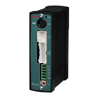
Page 20: Name For Each Parts And Their Functions
Name for Each Parts and Their Functions Pictures show ASEP, It should be the same for PSEP and DSEP. 3) StatusLED 2) LED for ABS (for SV, ALM and EMG) (It is not equipped for Incremental Type and DSEP) 4) SIO Connector 5) PIO Connector 6) Motor ·... - Page 21 It is the connector to supply the power to the controller and to the control board. Pin No. Signal Description For Brake Forced Release Power Supply (ASEP/PSEP) Keep DSEP disconnected. Motor Driving Power Supply Positive side of the 24V power supply Negative side of the 24V power supply EMG’s Confi...
-
Page 22: Actuator Axes
Actuator Axes Refer to the pictures below for the actuator axes that can be controlled by ASEP/PSEP and DSEP. (There are some types that cannot be controlled depending on the controller. Check the catalog for the details.) 0 defi nes the home position, and items in ( ) are for the home-reversed type (option). - Page 23 Gripper Type (Note) Finger Attachment (Note) Finger Attachment Note: Finger attachment is not included in the actuator package. Please prepare separately. Rotary Type (330° Rotation Specification) (Multi-Rotation Specification) − 330°...
-
Page 24: Starting Procedures
Starting Procedures When using this product for the fi rst time, make sure to avoid mistakes and incorrect wiring by referring to the procedure below. Check of Packed Items No→ Contact our distributor or us. Are there all the delivered items? ↓... -
Page 25: Specifi Cations Check
1. Specifi cations Check Product Check This product is comprised of the following parts if it is of standard confi guration. If you fi nd any fault in the contained model or any missing parts, contacts us or our distributer. 1.1.1 Parts Part Name... -
Page 26: Instruction Manuals Related To This Product, Which Are Contained In The Instruction Manual (Cd/Dvd)
A S E P – C – 2 0 I L A – N P – 0 – 0 – A B U – * * <Series> <Identification for IAI use only> * There is no identification in some cases. - Page 27 P S E P – C – 2 0 P I – N P – 0 – 0 – A B U – H – * * <Series> <Identification for IAI use only> * There is no identification in some cases.
-
Page 28: Basic Specifi Cations
Basic Specifications Specifications Item ASEP PSEP DSEP Number of controlled axes 1-axis Power-supply voltage 24V DC ±10% Control power capacity 0.5A (For Simple Absolute Type,0.8A) Load Motor type Low Power (Note 1) (Note 2) Rated MAX. Rated MAX. Rated MAX. - Page 29 Item ASEP PSEP DSEP Forcibly releasing of None None electromagnetic brake switch Brake cannot Supply 24V DC 150mA to BK on power connector when be compulsorily a compulsory release of the brake is required. released. Dielectric withstanding voltage/ 500V DC 10MW...
-
Page 30: External Dimensions
[ASEP/PSEP/DSEP-C] [Dust-Proof Cover : ASEP/PSEP/DSEP-CW] Front View Side View Front View Side View 107mm 110mm 34mm 105.7mm 30mm 72.2mm Bottom View Bottom View [Absolute Battery Unit SEP-ABUM (only applies to ASEP/PSEP)] Side View Front View 105mm 30mm 72.2mm Bottom View... -
Page 31: I/O Specifi Cations
I/O Specifi cations 1.4.1 PIO Input and Output Interface Input Section Output Section Input Voltage 24V DC10% Load Voltage 24V DC Peak Load Electric Specifi - Input Current 4mA 1circuit 50mA/1circuit Current cation ON Voltage MIN.18V DC ON/OFF Voltage Leakage Current MAX.0.1mA/1point OFF Voltage MAX.6V DC Controller... -
Page 32: Installation Environment
Installation Environment This product is capable for use in the environment of pollution degree 2 or equivalent. *1 Pollution Degree 2: Environment that may cause non-conductive pollution or transient conductive pollution by frost (IEC60664-1) Do not use this product in the following environment. ... -
Page 33: Installation And Noise Elimination
Installation and Noise Elimination (1) Noise Elimination Grounding (Frame Ground) Other Controller equipment Connect it using an earth cable Other Other Controller made of soft copper with the diameter equipment equipment of AWG16 (1.25mm Do not share the ground wire with or connect to other equipment. - Page 34 (4) Heat Radiation and Installation Conduct design and manufacture in consideration of the control box size, controller layout and cooling in such a way that the temperature around the controller will be 40C or less. Min. 20mm Min. 50mm DIN Rail Ensure enough space for wiring.
-
Page 35: Wiring
FG Connector Class D grounding (Formerly Class-III grounding : Grounding resistance at 100Ω or less) (Note 1) Connection Cable between Controller and Absolute Battery CB-APSEP-ABM005• • • Applicable Controller : ASEP-C-□-□-□-0-ABUM□ PSEP-C-□-□-□-0-ABUM□ CB-APSEP-AB005• • • Applicable Controller : ASEP-C-□-□-□-0-ABU□ (Existing models: Not complied with UL) PSEP-C-□-□-□-0-ABU□... -
Page 36: Pio Pattern Selection And Pio Signal
Air Cylinder Movement) control function as for the air cylinder. Dedicated Backward Backward Cable The target position Position Detection Position Detection ASEP, (LS0) (LS0) PSEP, Forward setting (forward position Forward DSEP Position Detection Solenoid Position Detection (LS1) - Page 37 (Position Data) Change) control function as for PL C Dedicated the air cylinder. Backward Backward Cable Position Detection P(Air) Position Detection ASEP, (LS0) (LS0) The change-over PSEP, Forward Forward Position Detection DSEP Position Detection between the positioning (LS1)
- Page 38 The pressing operation is available. Note: The air cylinder circuit is described with the symbols for the signals corresponding to those in ASEP/PSEP/DSEP. [Refer to the next page for the details of each signal.]...
- Page 39 (2) PIO Pattern and Signal Assignment Pattern Point-to-Point Point-to-Point Point-to-Point 3-Point 3-Point Point-to-Point Movement Movement Movement Movement Movement Reciprocating (Standard) (Movement (Target Position (2-Input) (3-Input) Movement Speed Setting) Setting Change) (Continuous Reciprocating Operation) Cable Input/ Single Double Single Double Single Double Double Color...
- Page 40 (3) List of PIO Signal Functions Signal Symbol Signal Name Function Type It is the common power source for I/O circuit. The positive () side of 24V I/O Power Supply Power DC is connected. Input It is the common power source for I/O circuit. The positive () side of 24V I/O Power Supply ...
-
Page 41: Circuit Diagram (Example)
Power/Emergency Stop Circuit Emergency Stop Switch Emergency for Device Stop Release (System) Switch ASEP/PSEP/DSEP Power Supply Connector Turn ON to Release Brake EMG (Emergency Stop Input) Brake Power Sopply BK (BK connection not required for DSEP) Motor Power Sopply Pattern 0 : Point-to-Point Movement (Standard) - Page 42 Pattern 1 : Point-to-Point Movement (Movement Speed Change) 1) Single Solenoid System 0V (NPN Type) 24V DC (NPN Type) 24V DC (PNP Type) 0V (PNP Type) ASEP/PSEP/DSEP PIO Connector 24V DC 0V Supply Supply Load Backward Position Detection/ Movement Signal...
- Page 43 Pattern 2 : Point-to-Point Movement (Target Position Change) 1) Single Solenoid System 0V (NPN Type) 24V DC (NPN Type) 24V DC (PNP Type) 0V (PNP Type) ASEP/PSEP/DSEP PIO Connector 24V DC 0V Supply Supply Load Backward Position Detection/ Movement Signal...
- Page 44 Pattern 3 : 3-Point Movement (2-Input) 0V (NPN Type) 24V DC (NPN Type) 24V DC (PNP Type) 0V (PNP Type) ASEP/PSEP/DSEP PIO Connector 24V DC 0V Supply Supply Load Backward Position Detection/ Movement Signal 1 LS0/PE0 Backward Positioning Completion Forward Position Detection/...
- Page 45 Input Emergency Stop to Multiple Controllers Touch Panel +24V Teaching SIO Converter EMGB EMG1 PORT EMGA Switch External External EMG ASEP/PSEP/DSEP Reset Switch Switch EMG2 EMG (Emergency Stop Input) ASEP/PSEP/DSEP EMG (Emergency Stop Input) ASEP/PSEP/DSEP EMG (Emergency Stop Input)
- Page 46 RCP3 CB-APSEP-MPA□□□ ASEP, PSEP Extension Cable : CB-APSEP-MPA□□□JY(JYP) RCA2, RCL CB-ASEP-MPA□□□ ASEP [10] Connection to Absolute Battery Unit (Limited only to ASEP/PSEP applicable for Simple Absolute Type) Absolute Battery Unit (SEP-ABUM) ASEP/PSEP Connection Cable between Controller and BATT Absolute Battery...
-
Page 47: Wiring Method
Wiring Method 2.4.1 Wiring Layout of Power Supply Connector The wires of the power supply and the emergency stop circuit are to be connected to the enclosed connector (plug). trip the sheath of the applicable wires for 7mm and insert them to the connector. Push a protrusion beside the cable inlet with a small slotted screwdriver to open the inlet. -
Page 48: Wiring Layout Of Fg Terminal Block
2.4.2 Wiring Layout of FG Terminal Block FG is to be connected to a screwless terminal block. Strip the sheath of the applicable wires for 11mm and insert them to the connector. Push a protrusion beside the cable inlet with a small slotted screwdriver to open the inlet. After inserting a cable, remove the screwdriver from the protrusion to fi... -
Page 49: Connection To Actuator
For Simple Absolute applicable type, remove the absolute battery connector from the controller before connecting the cable. ● Motor • Encoder Connector Specifi cations Connector Name Cable Side PADP-24V-1-S Controller Side S24B-PADSS-1 Signal Name Applicable Contents Wire ASEP PSEP DSEP Diameter A B Motor Driving Line /A /B BK LS BK... -
Page 50: Connection Of Pio
Also, the end of the cable harness to be connected to the host controller (PLC, etc.) is just cut and no treatment is conducted so the wiring layout can be performed freely. Model : CB-APSEP-PIO□□□···For ASEP-C, PSEP-C (□□□ shows the cable length L Example.0202m) ●... -
Page 51: Sio Connector Connection
2.4.5 SIO Connector Connection SIO connectors can be used not only for the connection of teaching tool, but also for the connection of the host controller (PLC, touch panel and PC). For the operation, refer to the instruction manual of each module. [Refer to Instruction manuals related to this product, which are contained in CD/DVD.] Touch Panel Teaching... -
Page 52: Battery Connector Connection (For Simple Absolute Type)
The absolute battery unit is to be connected to the battery connector. Connect the dedicated cable enclosed with the absolute battery unit. Connection Cable between Controller and Absolute Battery : CB-APSEP-AB005 ASEP- □ - □ - □ -0-ABUM Applicable Controller PSEP- □ - □ - □ -0-ABUM (Absolute Battery Unit) Connection Cable [Refer to 1.10.9]... - Page 53 Battery Name NiMH battery (FDK Corporation) Model AB-7 Rated 3.6V 3300mAh Nominal 3.6V 3700mAh Battery Life (reference) Approximately 3 years (It may vary depending on the usage condition.) Charging Time Approximately 72 hours Note: About Battery Charge and Discharge When using for the fi rst time or the fi rst time after the battery is replaced, do not charge the battery for more than 72 hours in a row.
-
Page 54: Operation
Continuous It is selectable only when “Double” is selected in “2. System Operation Type Operation Mode (Solenoid System)”. (Solenoid /Momentary For the signal sent from PLC to ASEP, PSEP or ○ ○ ○ ○ Type) Operation Type DSEP, select “Continuous Operation” (level signal) or (Continuous “Momentary Operation”... - Page 55 PIO Pattern Setting Range Setting Items Contents (Set in delivery) Output Signal Limit Switch The actuator is moved and the signal output system Type /Positioning after the positioning completion is selected. (Limit Switch) • Limit Switch : When the actuator reaches the target position, it is turned ON.
-
Page 56: Position Data Setting
3.1.2 Position Data Setting Set the following items in the position data editing window of the PC software menu or by selecting “Position Setting” in the Touch Panel Teaching menu. [Refer to the PC Software or Touch Panel Teaching Instruction Manual for the details] Forward Intermediate Backward... - Page 57 Note: Regarding to Acceleration/Deceleration Speed Setting (1) Do not have the setting to exceed the rated acceleration/deceleration speed that is specifi ed in the catalog or this Instruction Manual. The setting that exceeds the rated acceleration/ deceleration speed may shorten the actuator life remarkably. (2) Consider to lower the acceleration/deceleration speed when a shock or vibration is applied to the actuator or work.
- Page 58 [Pressing towards Backward Position or Intermediate Position Pulling Action] Velocity Time Pressing Width Backward Pressing Forward Position Start Position Position (Intermediate Position) 7) Energy-Saving Function … When it is set to “Enable”, the servo-motor is turned OFF automatically after the positioning is completed and the specifi ed time period passes.
- Page 59 When the position data is to be changed for the Operation Pattern (PIO Pattern) No. 2, in addition to the position data items for the forward position and backward position, the position data items for the changed forward position and changed backward position, are set. ...
-
Page 60: Absolute Reset
3.1.3 Absolute Reset (This function is effective only when the controller and actuator are the absolute type). When the power to the machine is turned ON for the fi rst time, perform the Absolute Reset. Procedure : After the power is turned ON, an absolute encoder error detection error occurs. Turn ON the RES signal (IN2), reset the alarm on the alarm window displayed on the PC software, or touch “RES”... -
Page 61: Power-Up And Pio Control
Power-up and PIO Control 3.2.1 Control of Input Signal The input signal of this controller has the input time constant of 7msec considering the prevention of wrong operation by chattering and noise. Therefore, ensure the continuous signal for more than 7msec for each input signal. The signal cannot be identifi... -
Page 62: Power Input
SON signal. When it is set to “Disable” the servo-motor is turned ON automatically. Warning: For ASEP and PSEP The magnetic pole phase detection may not be performed normally if the servo is turned on near the mechanical end, and may cause such problems like an abnormal operation, magnetic pole not being defi... -
Page 63: Home-Return
3.2.3 Home-return Home-return operation is performed when turning the Movement Signal 1 (ST0) on if the home return has not yet done since the power is turned on. 1) If the operation pattern is “Point-to-Point Movement (Single Solenoid)” If the home return is not conducted on the operation panel yet, the fi rst Movement Signal (ST0) will bring the actuator to the home position. -
Page 64: Timing Chart
Timing Chart [1] Point-to-Point Movement (For Single Solenoid System) ••• PIO Pattern 0 to 2 When the ST0 is turned “ON”, the positioning to the backward position is performed and when the ST0 is turned “OFF”, the positioning to the forward position is performed. Movement Signal (ST0) Backward Position Detection Output (LS0) Forward Position Detection Output (LS1) - Page 65 [3] Pause during Movement (For Single Solenoid System) ••• PIO Pattern 0 to 2 * Inputting the STP signal pauses the actuator motion. A forward position movement example is shows as follows. Movement Signal (ST0) Pause Signal (*STP) Forward Position Detection Output (LS1) Forward Positioning Completion Output (PE1) Positioning Band (Parameter No.
- Page 66 [6] Speed Change during the Movement (For Double Solenoid System) ••• PIO Pattern 1 The movement speed is changed during the actuator’s movement to the target position. When the movement command is issued with SPDC turned ON, the actuator is moved at the changed speed specifi...
- Page 67 3-Point Movement (For Single Solenoid System) ••• PIO Pattern 3 With the combination of ST0 and ST1, the actuator is moved to the target position. Backward Position Movement Signal (ST0) Refer to the table below for the combination of movement Forward Position Movement Signal (ST1) signals.
- Page 68 [10] Reciprocating Operation between 2 Points ••• PIO Pattern 5 Reciprocating operation is performed continuously between the forward and backward positions while ASTR signal is ON. Once ASTR signal is turned OFF, the actuator positions at the current target position and stops. Continuous Reciprocating Operation Signal (ASTR) Backward Position Detection Output...
-
Page 69: User Parameters
Current Limitation in Pressing and Bridging [0: Current limitation value while Set the torque after the actuator reaches the target position moving (ASEP, DSEP), without hitting the work in the pressing operation in midway. 0 to 1 Current limitation value while... - Page 70 Name Initial Value Setting Range Remarks Set the standard for the absolute data storage time. Parameter Encoder Max. Rotation Reference No.19 Setting Speed [rpm] for Battery Retention When the When the Time connected connected (reference) actuator is a actuator is Absolute Battery Retention [day] model other...
-
Page 71: Servo Adjustment
3.5.1 Adjustment for ASEP and PSEP (Note) Make an adjustment following Section 3.5.2 if using DSEP. Situation that Requires... -
Page 72: Adjustment For Dsep
Integrated Gain Order Settings Settings 1259 2368 2833 ● If load is above 0.3kg; Velocity Loop Velocity Loop Setting Integrated Gain Integrated Gain Order Settings Settings 1171 2081 2997 4683 If no improvement in operation is confi rmed, please contact IAI. - Page 73 Situation that Requires How to Adjust Adjustment Abnormal noise is Change “Velocity Loop Proportional Gain” and “Velocity Loop generated/Especially, Integrated Gain” to the following values and check the operation. when stop and Speed Loop Proportional Gain : 32 Velocity Loop Integrated Gain : 231 operation in low speed (less than 20mm/sec), comparatively high...
-
Page 74: Servo Parameter
3.5.3 Servo Parameter • User Parameter No. 3 Servo-Motor Gain Number This parameter decides the responsibility to the position control loop. When the set value is increased, the follow-up ability to the position command becomes better. However, if the value is too large, an overshoot is caused easily. When the set value is too low, the follow-up ability to the position command is degraded and it takes longer time to complete the positioning. -
Page 75: Alarm
Alarm 3.6.1 Alarm Level The alarms are classifi ed to 2 types of levels by the content of the error. Alarm Level Status Lamp Condition in Error Occurrence Cancellation Method Actuator compulsory stop Perform a reset with the reset Operation Red Light is (Motor power (servo) turns signal (RES) or by using a teaching... -
Page 76: Alarm Codes And Trouble Shooting
3.6.2 Alarm Codes and Trouble Shooting Error Code Alarm Name Cause/Treatment Level Movement Command in Cause : The movement command is input while the servo-motor is turned OFF. Servo-Motor OFF Treatment : Input “SON” signal to turn ON the servo-motor. Movement Command in Cause : The movement command is input while the home return has not been completed. - Page 77 Error Code Alarm Name Cause/Treatment Level For this controller, when the servo-motor is turned ON for the fi rst time after the power is input, the magnetic pole phase detection (pole sensing) is performed. At that time, the magnetic pole phase is not detected after the specifi...
- Page 78 Error Code Alarm Name Cause/Treatment Level The motor operation is not available for 2 seconds or more after the movement command is received and before the actuator reaches the target position. Cause : (1) A looseness in the connection section of the actuator connecting cable or wire breakage is considered.
- Page 79 Error Code Alarm Name Cause/Treatment Level Cause : (1) In the case that the actuator is vertically installed and the target position is close to the soft limit, because the load is too high, or the deceleration setting is too high, an over-chute might occur and the actuator might exceed the soft limit.
- Page 80 Error Code Alarm Name Cause/Treatment Level Cause : The current value is increased to the velocity value more than specifi ed in the motor speed setting due to an external force, etc., while the power is turned OFF. Treatment : Take the measure so that the actuator is not moved at the speed more than the set Operation Absolute Encoder Error value while the power is turned OFF.
-
Page 81: Appendix
• Do not change the setting of push speed (parameter No. 7). If you must change the push speed, consult IAI. • If, among the operating conditions, the positioning speed is set to a value equal to or smaller than the push speed, the push speed will become the set speed and the specifi... - Page 82 Maximum Minimum Maximum Rated Minimum No. of Lead Maximum speed acceleration/ push push push Actuator Feed Mounting speed Type encoder deceleration force force speed series screw direction pulses [mm] [mm/s] [mm/s] [mm/s] Horizontal Vertical Ball Horizontal/ RA6C screw vertical Horizontal/ vertical Horizontal Vertical...
- Page 83 Maximum Minimum Maximum Rated Minimum No. of Lead Maximum speed acceleration/ push push push Actuator Feed Mounting speed Type encoder deceleration force force speed series screw direction pulses [mm] [mm/s] [mm/s] [mm/s] 380 (at 50st) 540 (at 100st) 660 (at 150st) 770 (at 200st) 860 (at 250st) 940 (at 300st)
- Page 84 Maximum Minimum Maximum Rated Minimum No. of Lead Maximum speed acceleration/ push push push Actuator Feed Mounting speed Type encoder deceleration force force speed series screw direction pulses [mm] [mm/s] [mm/s] [mm/s] 380 (at 50st) 540 (at 100st) 660 (at 150st) 770 (at 200st) 860 (at 250st) 940 (at 300st)
- Page 85 Maximum Minimum Maximum Rated Minimum No. of Lead Maximum speed acceleration/ push push push Actuator Feed Mounting speed Type encoder deceleration force force speed series screw direction pulses [mm] [mm/s] [mm/s] [mm/s] 380 (at 50st) Horizontal 470 (at 100st) 533 (at 150 to 750st) Vertical 480 (at 800st) Ball...
- Page 86 Maximum Minimum Maximum Rated Minimum No. of Lead Maximum speed acceleration/ push push push Actuator Feed Mounting speed Type encoder deceleration force force speed series screw direction pulses [mm] [mm/s] [mm/s] [mm/s] 600 (at 50 to 800st) Horizontal 600 (at to 900st) 515 (at to 1000st) 333 (at 50 to 800st) Vertical...
- Page 87 Maximum Minimum Maximum Rated Minimum No. of Lead Maximum speed acceleration/ push push push Actuator Feed Mounting speed Type encoder deceleration force force speed series screw direction pulses [mm] [mm/s] [mm/s] [mm/s] Gear ratio: 15 (deg/s) 400 (deg/s) 1/30 RTBS Gear ratio: 10 (deg/s) 266 (deg/s)
- Page 88 Maximum Minimum Maximum Rated Minimum No. of Lead Maximum speed acceleration/ push push push Actuator Feed Mounting speed Type encoder deceleration force force speed series screw direction pulses [mm] [mm/s] [mm/s] [mm/s] 180 (at 25st) 16.1 200 (at 50 to 100st) Lead Horizontal/ RA2AC...
- Page 89 Maximum Minimum Maximum Rated Minimum No. of Lead Maximum speed acceleration/ push push push Actuator Feed Mounting speed Type encoder deceleration force force speed series screw direction pulses [mm] [mm/s] [mm/s] [mm/s] Horizontal 380 (at 50st) 12.5 500 (at 100 to 500st) Vertical Ball Horizontal...
- Page 90 Maximum Minimum Maximum Rated Minimum No. of Lead Maximum speed acceleration/ push push push Actuator Feed Mounting speed Type encoder deceleration force force speed series screw direction pulses [mm] [mm/s] [mm/s] [mm/s] 380 (at 50st) 540 (at 100st) Horizontal 600 (at 150 to 550st) 570 (at 600st) 490 (at 650st) 425 (at 700st)
- Page 91 Maximum Minimum Maximum Rated Minimum No. of Lead Maximum speed acceleration/ push push push Actuator Feed Mounting speed Type encoder deceleration force force speed series screw direction pulses [mm] [mm/s] [mm/s] [mm/s] 380 (at 50st) 540 (at 100st) Horizontal 600 (at 150 to 550st) 570 (at 600st) 490 (at 650st) 425 (at 700st)
- Page 92 Maximum Minimum Maximum Rated Minimum No. of Lead Maximum speed acceleration/ push push push Actuator Feed Mounting speed Type encoder deceleration force force speed series screw direction pulses [mm] [mm/s] [mm/s] [mm/s] Horizontal Vertical Ball Horizontal TA6C screw Vertical Horizontal 3.75 Vertical Horizontal...
- Page 93 ASEP Minimum Maximum Rated Motor No. of Minimum Maximum acceleration/ Lead Mounting Maximum speed push push push Actuator Feed output speed deceleration Type encoder force force speed series screw direction pulses [mm] [mm/s] [mm/s] [mm/s] Horizontal/ Energy-saving spec.: 0.3 12.5 vertical High acc/dec spec.:1.0...
- Page 94 Minimum Maximum Rated Motor Minimum Maximum acceleration/ No. of Lead Mounting Maximum speed push push push Actuator Feed output speed deceleration Type encoder series screw direction force force speed pulses [mm] [mm/s] [mm/s] [mm/s] Energy-saving spec.: 0.3 Horizontal/ vertical High acc/dec spec.:1.0 Energy-saving spec.: 0.3 Horizontal/ vertical...
- Page 95 Minimum Maximum Rated Motor Minimum Maximum acceleration/ No. of Lead Mounting Maximum speed push push push Actuator Feed output speed deceleration Type encoder series screw direction force force speed pulses [mm] [mm/s] [mm/s] [mm/s] Horizontal/ vertical Horizontal/ vertical Horizontal/ 3.75 vertical Ball RA4D...
- Page 96 Minimum Maximum Rated Motor Minimum Maximum acceleration/ No. of Lead Mounting Maximum speed push push push Actuator Feed output speed deceleration Type encoder series screw direction force force speed pulses [mm] [mm/s] [mm/s] [mm/s] Horizontal 6.25 Ball Vertical SRA4R screw Horizontal 3.12 Vertical...
- Page 97 Minimum Maximum Rated Motor Minimum Maximum acceleration/ No. of Lead Mounting Maximum speed push push push Actuator Feed output speed deceleration Type encoder series screw direction force force speed pulses [mm] [mm/s] [mm/s] [mm/s] 1300 (at50 to 500st) Horizontal 1160 (at 550st) Energy-saving spec.: 0.3 990 (at 600st) Vertical...
- Page 98 Minimum Maximum Rated Motor Minimum Maximum acceleration/ No. of Lead Mounting Maximum speed push push push Actuator Feed output speed deceleration Type encoder series screw direction force force speed pulses [mm] [mm/s] [mm/s] [mm/s] 12.5 Ball Horizontal/ screw vertical 6.25 Ball Horizontal/ (arm...
- Page 99 Minimum Maximum Rated Motor Minimum Maximum acceleration/ No. of Lead Mounting Maximum speed push push push Actuator Feed output speed deceleration Type encoder series screw direction force force speed pulses [mm] [mm/s] [mm/s] [mm/s] Horizontal 5.72 Vertical Horizontal Ball 3.81 screw Vertical Horizontal...
- Page 100 Minimum Maximum Rated Motor Minimum Maximum acceleration/ No. of Lead Mounting Maximum speed push push push Actuator Feed output speed deceleration Type encoder series screw direction force force speed pulses [mm] [mm/s] [mm/s] [mm/s] Horizontal Vertical Horizontal Ball SA3C screw Vertical Horizontal Vertical...
- Page 101 Minimum Maximum Rated Motor Minimum Maximum acceleration/ No. of Lead Mounting Maximum speed push push push Actuator Feed output speed deceleration Type encoder series screw direction force force speed pulses [mm] [mm/s] [mm/s] [mm/s] 380 (at 50st) 540 (at 100st) 660 (at 150st) 770 (at 200st) 860 (at 250st)
- Page 102 Minimum Maximum Rated Motor Minimum Maximum acceleration/ No. of Lead Mounting Maximum speed push push push Actuator Feed output speed deceleration Type encoder series screw direction force force speed pulses [mm] [mm/s] [mm/s] [mm/s] 380 (at 50st) 540 (at 100st) 660 (at 150st) 770 (at 200st) 860 (at 250st)
- Page 103 Minimum Maximum Rated Motor Minimum Maximum acceleration/ No. of Lead Mounting Maximum speed push push push Actuator Feed output speed deceleration Type encoder series screw direction force force speed pulses [mm] [mm/s] [mm/s] [mm/s] 3.81 Lead Horizontal/ TC3N 1048 screw vertical 0.95 3.81...
- Page 104 Minimum Maximum Rated Motor Minimum Maximum acceleration/ No. of Lead Mounting Maximum speed push push push Actuator Feed output speed deceleration Type encoder series screw direction force force speed pulses [mm] [mm/s] [mm/s] [mm/s] Horizontal Vertical Horizontal Ball TA4R screw Vertical Horizontal Vertical...
-
Page 105: Pressing Force And Current Limit Value
Pressing Force and Note Current Limit Value • The correlation of the pressing force and the current limit value is the rated pressing speed (in the setting at the RCP2 Series Rod Type delivery) and is a reference value. • Use the actuator with the setting above the minimum RA2C Type pressing force value. - Page 106 Short Length Type RCP2 Series SRA4R/SRGS4R/SRGD4R Lead 2.5 Lead 5 Current Limit Value (Ratio %) RCP2 Series Slider Type SA5C/SA6C/SS7C Type SA7C Type Current Limit Value (Ratio %) Current Limit Value (Ratio %) SA8C Type Current Limit Value (Ratio %)
- Page 107 RCP2 Series Gripper Current Limit Value (Ratio %) Current Limit Value (Ratio %) Current Limit Value (Ratio %) Current Limit Value (Ratio %) Standard Type High Speed Type Current Limit Value (Ratio %)
- Page 108 RCP2 Series Three-finger Gripper Current Limit Value (Ratio %) Current Limit Value (Ratio %) Current Limit Value (Ratio %) Current Limit Value (Ratio %)
- Page 109 RCP3 Series Thin and Small Rod Type *Inside the red box is the specification value RA2AC/RA2AR Lead1 RA2BC/RA2BR Lead4 Current Limit Value (Ratio %) Current Limit Value (Ratio %) RA2AC/RA2AR Lead2 RA2BC/RA2BR Lead4 Current Limit Value (Ratio %) Current Limit Value (Ratio %) RA2AC/RA2AR Lead4 RA2BC/RA2BR Lead6 Current Limit Value (Ratio %)
- Page 110 RCP3 Series Slider Type SA3C Type SA4CType Current Limit Value (Ratio %) Current Limit Value (Ratio %) SA5C/SA6C Type Current Limit Value (Ratio %) Thin and Small Table Type RCP3 Series TA3C Type TA4C/TA4R Type Current Limit Value (Ratio %) Current Limit Value (Ratio %) RCP3 Series Table Type...
- Page 111 RCL Series Micro Cylinder Current Limit Value (Ratio %) RCD Series Ultra-small ROBO Cylinder RA1D Type 5.98 4.99 4.01 3.02 2.60 2.16 2.04 1.72 1.28 1.05 0.85 0.41 Current Limit Value (Ratio %)
-
Page 112: Warranty
5. Warranty Warranty Period One of the following periods, whichever is shorter: • 18 months after shipment from our factory • 12 months after delivery to a specifi ed location Scope of Warranty Our products are covered by warranty when all of the following conditions are met. Faulty products covered by warranty will be replaced or repaired free of charge: (1) The breakdown or problem in question pertains to our product as delivered by us or our authorized dealer. -
Page 113: Conditions Of Conformance With Applicable Standards/Regulations, Etc., And Applications
Conditions of Conformance with Applicable Standards/ Regulations, Etc., and Applications (1) If our product is combined with another product or any system, device, etc., used by the customer, the customer must fi rst check the applicable standards, regulations and/or rules. The customer is also responsible for confi... -
Page 114: Change History
Change History Revision Date Revision Description 2010.11 First Edition 2011.01 Second Edition • P23 Pollution Standard Number changed from “EN60947-5-1” to “IEC60664-1” 2011.04 Third Edition • Swapped over the page for CE Marking • Explanation added regarding Absolute Battery 2011.07 Fourth Edition •... - Page 116 825, PhairojKijja Tower 12th Floor, Bangna-Trad RD., Bangna, Bangna, Bangkok 10260, Thailand TEL +66-2-361-4458 FAX +66-2-361-4456 The information contained in this document is subject to change without notice for purposes of product improvement. Copyright © 2014. Jnl. IAI Corporation. All rights reserved. 14.07.000...
Need help?
Do you have a question about the ASEP and is the answer not in the manual?
Questions and answers