Sign In
Upload
Manuals
Brands
IAI Manuals
Controller
PCON-CB series
IAI PCON-CB series Manuals
Manuals and User Guides for IAI PCON-CB series. We have
3
IAI PCON-CB series manuals available for free PDF download: Instruction Manual, First Step Manual
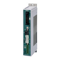
IAI PCON-CB series Instruction Manual (538 pages)
Brand:
IAI
| Category:
Controller
| Size: 40.24 MB
Table of Contents
Table of Contents
5
Safety Guide
11
Precautions for Handling
18
Precautions for PC Connection to Controller Grounded at Positive Terminal of 24V DC Power Supply
23
International Standard Compliance
24
Actuator Coordinate System
25
Overview
30
System Configuration
32
Name for each Parts and Their Functions
33
Starting Procedures
38
Product Check
45
Parts
45
Teaching Tool
46
Product Check
46
How to Read the Model Plate
47
How to Read the Model
48
Operation Modes and Functions
49
Operation Mode of Controller
49
Positioner Mode (PCON-CB/CBP I/O Type: NP and PN)
50
Positioner Mode
50
Pulse Train Control Mode (PCON-CB/CBP I/O Type: PLN and PLP)
52
Pulse Train Control Mode
52
Field Network Operation Modes and Features
53
List of Basic Specifications
55
External View
57
CB/CBP Type
57
CB Type
59
CB Type
60
CFB Type
61
CFB Type
62
Absolute Battery Unit (Option for Simple Absolute Type)
63
I/O Specifications
64
PIO Input and Output Interface
64
Pulse Train Input Output Interface
65
Options
66
Pulse Converter (Model: AK-04)
66
Absolute Battery • Absolute Battery Unit
67
Loadcell
68
Installation and Storage Environment
70
Installation Environment
70
Storage and Preservation Environment
70
Noise Elimination and Mounting Method
71
Noise Elimination
71
Installation and Mounting
72
Positioner Mode (PIO Control)
76
Wiring Diagram (Connection of Devices)
76
PIO Pattern Selection and PIO Signal
77
Wiring
82
Pulse Train Control Mode
101
Wiring Diagram (Connection of Devices)
101
I/O Signals in Pulse Train Control Mode and each Functions
102
Each Functions
102
Wiring
104
Wiring Method
117
Wiring Layout of Power Supply Connector
117
Connection to Actuator
118
Connection of PIO
119
Connection of Pulse Train Signal
120
SIO Connector Connection
122
Field Network Connector of PIO
123
Basic Operation
127
How to Turn on Power
127
Basic Operation Methods
128
Parameter Settings
134
Operation in Positioner Mode
135
Operation Modes of Rotary Actuator in Multiple Rotation Mode and Command Limitations
137
Mode and Command Limitations
137
Set of Position Table
138
Control of Input Signal
147
Operation Ready and Auxiliary Signals (Common to Patterns 0 to 7)
148
Operation Ready and Auxiliary Signals
148
(Common to Patterns 0 to 7)
159
Operation with the Position No. Input (PIO Patterns 0 to 3 and 6)
162
Direct Position Specification (Operation of PIO Pattern 4 and 7)
189
Direct Position Specification (PIO Pattern 5)
211
Preparation for Operation in Force Sensor Pressing (Loadcell Calibration)
222
Pulse Train Control Mode
227
I/O Signal Controls
229
Operation Ready and Auxiliary Signals
230
Pulse Train Input Operation
242
Settings of Basic Parameters Required for Operation
246
Parameter Settings Required for Advanced Operations
250
Operation of Field Network Type
254
Absolute Reset
255
How to Perform Absolute Reset
256
Absolute Battery Charge
261
Collision Detection Feature
264
Collision Detection Judgement
265
How to Settings
266
How to Adjustment
267
Power-Saving Function
268
AUTO Servo off and Full Servo Function
268
Auto Current down Function
272
Parameter List
277
Parameter Details
282
Servo Adjustment
333
Periodic Inspection
338
Periodic Inspection Items
339
Requests When Replacing Units
341
Consumable Parts
342
Component Replacement
343
Replacement of Absolute Battery
343
How to Replace Fan Unit
345
Preventive Maintenance Function
346
Maintenance Information
346
Predictive Maintenance Function
349
Fan
349
Overload Warning
350
Action to be Taken Upon Occurrence of Problem
354
Fault Diagnosis
356
Impossible Operation of Controller
356
Positioning and Speed of Poor Precision (Incorrect Operation)
360
Positioning and Speed of Poor Precision
360
Generation of Noise And/Or Vibration
362
Impossible Communication
363
About Alarms
364
Simple Alarm Codes
364
Alarm Level
366
Alarm Details
367
Way to Set Multiple Controllers with 1 Teaching Tool
385
Connecting Example
386
Detailed Connection Diagram of Communication Lines
387
Axis No. Setting
388
Handling of E-CON Connector (How to Connect)
389
SIO Converter
390
Communications Cable
392
External Dimension
392
Conformity to Safety Category
393
System Configuration
393
Wiring and Setting of Safety Circuit
394
Examples of Safety Circuits
396
TP Adapter and Accessories
402
Example of Basic Positioning Sequence (PIO Pattern 0 to 3)
405
I/O Assignment
405
Ladder Sequence
406
List of Specifications of Connectable Actuators
416
Specifications for Actuators
416
Correlation Diagrams of Speed and Payload
458
Push Force / Gripping Force and Current Limit Value
512
Rotational Speed and Output Torque / Allowable Inertial Moment
523
Pressing Force / Pulling Force and Current Limit of Pulse Pressing
526
Warranty Period
528
Scope of the Warranty
528
Honoring the Warranty
528
Limited Liability
529
Advertisement
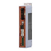
IAI PCON-CB series Instruction Manual (336 pages)
POWER CON PCON-CB Series
Brand:
IAI
| Category:
Controller
| Size: 17.02 MB
Table of Contents
Table of Contents
7
Power con Pcon-Cb/Lc
11
Safety Guide
15
Precautions in Operation
22
International Standards Compliances
25
Name for each Parts and Their Functions
26
Actuator Axes
30
Chapter 1 Specifications Check
33
Product Check
33
Parts
33
Teaching Tool
34
Instruction Manuals Related to this Product, Which Are Contained in the Instruction Manual (DVD)
34
How to Read the Model Plate
35
How to Read the Model
35
List of Basic Specifications
36
Appearance
38
CB Type・・・・・・For Incremental Screw-Fixed Type
38
CB Type・・・・・・For Incremental DIN Rail-Fixed Type
39
CB Type・・・・・・For Simple Absolute Screw-Fixed Type
40
CB Type・・・・・・For Simple Absolute DIN Rail-Fixed Type
41
CFB Type・・・・・For Incremental Screw-Fixed Type
42
CFB Type・・・・・For Incremental DIN Rail-Fixed Type
43
Absolute Battery Unit (Option for Simple Absolute Type)
44
I/O Specifications
45
PIO Input and Output Interface
45
Pulse Train Input Output Interface
46
Options
47
Pulse Converter : AK-04
47
Installation and Storage Environment
48
Installation Environment
48
Storage and Preservation Environment
48
Noise Elimination and Mounting Method
49
Chapter 2 Wiring
51
Positioner Mode (PIO Control)
51
Wiring Diagram (Connection of Devices)
51
PIO Pattern Selection and PIO Signal
52
Wiring
57
Power Supply Connector (for Power Supply and Emergency Stop)
57
Absolute Circuit (for Simplified Absolute Type Only)
61
Motor • Encoder Circuit
61
PIO Circuit
62
Pulse Train Control Mode
68
Wiring Diagram (Connection of Devices)
68
I/O Signals in Pulse Train Control Mode
69
PIO Pattern 6 (Incremental Type for Actuator)
69
PIO Pattern 7 (Incremental Type for Actuator)
70
Wiring
71
Power Supply Connector (for Power Supply and Emergency Stop)
71
Motor • Encoder Circuit
75
PIO Circuit
76
Circuits for Pulse Train Control
78
Power con Pcon-Cb/Lc
78
Wiring Method
79
Wiring Layout of Power Supply Connector
79
Connection to Actuator
80
Connection of PIO
81
Connection of Pulse Train Signal
82
SIO Connector Connection
83
Chapter 3 Operation
85
Basic Operation
85
Basic Operation Methods
85
Parameter Settings
88
Operation in Positioner Mode
89
PIO Pattern Selection and Main Functions
89
Overview of Major Functions
90
Operation Modes of Rotary Actuator in Multiple Rotation Mode and Command Limitations
90
Set of Position Table
91
(This Section Is Not Required in Selection of Pulse Train Control Mode.)
91
Control of Input Signal
96
Operation Ready and Auxiliary Signals = Common to Patterns 0 to 5
96
Emergency Stop Status (EMGS)
96
Operation Mode (RMOD, RMDS)
97
Servo on (SON, SV, PEND)
98
Home Return (HOME, HEND, PEND, MOVE)
99
Zone Signal and Position Zone Signal (ZONE1, ZONE2, PZONE)
103
Alarm, Alarm Reset (*ALM, RES)
105
Binary Output of Alarm Data Output (*ALM, PM1 to 8)
106
Brake Release (BKRL)
108
Operation with the Position No. Input = Operations of PIO Patterns 0 to 3
109
Positioning [Basic] (PC1 to PC**, CSTR, PM1 to PM**, PEND, MOVE, LOAD, TRQS)
109
Speed Change During the Movement
114
Pitch Feeding (Relative Movement = Incremental Feed)
115
Pressing Operation
117
Tension Operation
122
Multi-Step Pressing
124
Teaching by PIO (MODE, MODES, PWRT, WEND, JISL, JOG+, JOG-)
125
Pause and Operation Interruption (*STP, RES, PEND, MOVE)
127
Direct Position Specification (Solenoid Valve Mode 1) = Operation of PIO Pattern 4
129
Positioning [Basic] (ST0 to ST6, PE0 to PE6, PEND)
129
Pitch Feeding (Relative Movement = Incremental Feed)
131
Pressing Operation
133
Tension Operation
137
Multi-Step Pressing
139
Pause and Operation Interruption (ST*, *STP, RES, PE*, PEND)
140
Direct Position Specification (Solenoid Valve Mode 2) = Operation of PIO Pattern 5
142
Home Return (ST0, HEND)
142
Features of LS Signals (LS0 to 2)
146
Positioning [Basic] (ST0 to ST2, LS0 to LS2)
147
Speed Change During the Movement
149
Pause and Operation Interruption (ST*, *STP, RES, PE*, PEND)
151
Pulse Train Control Mode (for Pulse Train Type)
152
I/O Signal Controls
153
Power con Pcon-Cb/Lc
153
Operation Ready and Auxiliary Signals
153
Emergency Stop Status (*EMGS)
153
System Ready (PWR)
153
Operation Mode (RMOD, RMDS)
154
Compulsory Stop (CSTP)
155
Servo on (SON, SV)
155
Home Return (HOME, HEND)
156
Datum Position Move (RSTR, REND)
159
Zone (ZONE1, ZONE2)
160
Alarm, Alarm Reset (*ALM, RES)
161
Binary Output of Alarm Data Output (*ALM, ALM1 to 8)
161
Brake Forcible Release (BKRL)
162
Command Pulse Input (PP•/PP, NP•/NP)
163
Pulse Train Input Operation
163
Position Complete (INP)
164
Deviation Counter Clear (DCLR)
165
Torque Limit Select (TL, TLR)
165
Electronic Gear Setting
166
Settings of Basic Parameters Required for Operation
166
Format Settings of Command Pulse Train
168
Pulse Train Datum Position (Parameter No. 167)
168
Clearing Deviation During Servo off or Alarm Stop
169
Parameter Settings Required for Advanced Operations
169
Position Command Primary Filter Time Constant
169
Torque Limit
169
Compulsory Stop Input
170
Deviation Counter Clear Input
170
Error Monitor During Torque Limiting
170
Pulse Count Direction
170
Torque Limit Command Input
170
Chapter 4 Field Network
171
PCON-CB/CFB Type
171
Chapter 5 Collision Detection Feature
175
Collision Detection Judgement
175
Settings
176
Adjustment
176
Chapter 6 Power-Saving Function
177
Automatic Servo-Off and Full Servo Functions
177
Automatic Current Reduction Feature
180
Chapter 7 Absolute Reset and Absolute Battery
181
Absolute Reset
181
Absolute Reset Procedure from Teaching Tool
181
Absolute Reset Using PIO
184
Absolute Battery (for Simple Absolute Type)
186
For the Type to Attach Battery to Controller Side
186
When Using Absolute Battery Unit
186
Absolute Encoder Backup Specifications
186
Absolute Battery Charge
186
Absolute Battery Voltage Drop Detection
187
Replacement of Absolute Battery
188
For the Type to Attach Battery to Controller Side
188
When Using Absolute Battery Unit
189
Chapter 8 Parameter
191
Parameter List
192
Detail Explanation of Parameters
196
Servo Adjustment
224
Power con Pcon-Cb/Lc
224
Chapter 9 Troubleshooting
227
Action to be Taken Upon Occurrence of Problem
227
Fault Diagnosis
228
Impossible Operation of Controller
228
Positioning and Speed of Poor Precision (Incorrect Operation)
232
Generation of Noise And/Or Vibration
234
Impossible Communication
235
Alarm Level
236
Alarm List
237
Chapter 10 Appendix
247
Way to Set Multiple Controllers with 1 Teaching Tool
247
Connecting Example
247
Detailed Connection Diagram of Communication Lines
248
Axis No. Setting
248
Handling of E-CON Connector (How to Connect)
249
SIO Converter
250
Communications Cable
252
External Dimension
252
Conformity to Safety Category
253
System Configuration
253
Wiring and Setting of Safety Circuit
254
Examples of Safety Circuits
256
TP Adapter and Accessories
262
When Connecting Power Supply with + Grounding
264
Maintenance
265
Consumed Parts
265
Maintenance Information
265
Replacement of Fan (PCON-CFB)
266
Example of Basic Positioning Sequence (PIO Pattern 0 to 3)
267
I/O Assignment
267
Ladder Sequence
268
Operation and Stop Circuit
268
Servo on (Emergency Stop) Circuit
268
Pause Circuit
269
Reset Circuit
270
Home Return Circuit
271
Actuator Start Circuit
272
Decode Circuit of Positioning Complete Position no
272
Position 1 Operation Circuit
273
Position 2 Operation Circuit
274
Position 3 Operation Circuit
275
Commanded Position No. Output Ready Circuit
276
Commanded Position No. Output Circuit
277
Start Signal Output Circuit
277
Other Display Circuits (Zone 1, Position Zone, and Manual Mode)
278
List of Specifications of Connectable Actuators
279
Chapter 11 Warranty
331
Warranty Period
331
Scope of the Warranty
331
Honoring the Warranty
331
Limited Liability
331
Conditions of Conformance with Applicable Standards/Regulations, Etc., and Applications
332
Other Items Excluded from Warranty
332
Change History
333
IAI PCON-CB series First Step Manual (5 pages)
Brand:
IAI
| Category:
Industrial Equipment
| Size: 1.61 MB
Table of Contents
Installation Environment
2
Installation and Noise Elimination
2
Connection Diagram
3
Starting Procedures
5
Advertisement
Advertisement
Related Products
IAI PCON-CBP
IAI PCON-CFA
IAI PCON-C
IAI PCON-CG
IAI PCON-C. PCON-CG
IAI PCON-CA
IAI PCON-CGB series
IAI PCON-CGFB series
IAI PCON-CGFB
IAI PCON-CGBP
IAI Categories
Controller
Digital Camera
Security Camera
Gateway
Industrial Equipment
More IAI Manuals
Login
Sign In
OR
Sign in with Facebook
Sign in with Google
Upload manual
Upload from disk
Upload from URL