Table of Contents
Advertisement
Advertisement
Table of Contents

Related Manuals for Aqualisa dream


Summary of Contents for Aqualisa dream
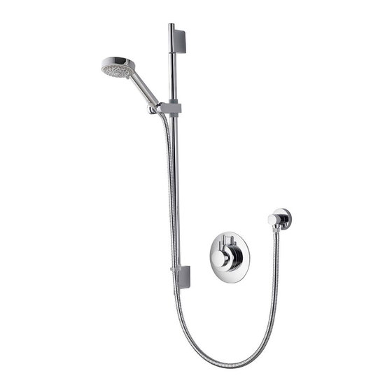
- Page 1 Dream Thermostatic mixer shower with 105mm Harmony head Installation guide...
-
Page 2: Table Of Contents
- Pump installation - Stored water capacities Combination boiler systems Balanced high pressure sytems Typical water systems System components Valve installation instructions - Dream concealed valve Harmony shower head installation p.12 - Adjustable height Harmony head p.12 - Fixed Harmony head p.15... -
Page 3: Introduction
If any doubt, please contact the appliance manufacturer before installation commences. Connections Dream products are designed for conventional supplies with HOT on the left and COLD on the right as viewed from the front. Dream shower valves incorporate ‘push fit’ type connections for use with 15mm British standard copper tube. -
Page 4: Flushing
Pressures The Dream cartridge is designed to operate from the mains at a maximum of 10bar. If the mains pressure likely to exceed 10bar, a ‘drop tight’ PRV must be fitted on the supply pipe after the main stopcock. A setting of 3bar is recommended. -
Page 5: Siting
Combination boiler/multipoint system Dream products are suitable for use with combination boiler systems. The combination boiler MUST have a minimum rating of 24kW (80,000 Btu) and be of the type fitted with a fully modulating gas valve. This is sufficient to operate one outlet at a time. - Page 6 Typical system diagrams Typical gravity system installation Typical pumped system installation...
- Page 7 Typical system diagrams continued Typical combination boiler system installation Typical UHW system installation Typical thermal storage unit system installation...
- Page 8 Components - Dream concealed with adjustable 105mm Harmony head Components - Dream concealed with fixed 105mm Harmony head...
-
Page 9: Dream Concealed Valve
Prior to starting ensure that you are familiar with the necessary plumbing regulations required to install the product correctly and safely. Dream concealed is supplied with universal fixings. If installing the product built in to a solid wall, chase out a suitable recess in the wall to receive the valve and pipe work. - Page 10 (the flow regulator is supplied in its own pack). The Dream valve is supplied with an outlet cap on the bottom of the valve allowing for a top outlet connection. The bottom outlet can be used by simply removing the cap and repositioning it on the top outlet.
- Page 11 Using a silicone-based lubricant, lubricate the supply pipe ends and whilst supporting the elbows push home the supply pipes ensuring the correct orientation for the inlet pipes (HOT left and COLD right as shown on the valve). Push the valve fully home until a definite stop is reached.
- Page 12 Apply a thin bead of silicone mastic into the groove on the rear of the wall plate and carefully push the wall plate into position ensuring correct horizontal alignment of the Aqualisa logo. Ensuring the red spacer ring is correctly fitted inside the temperature lever assembly, offer the lever assembly onto the valve, with the lever in the full cold (9 o’clock)
- Page 13 Slide the 15mm gripper ring down the projecting pipe flush with the wall spacer fitting. Trim the projecting pipe to a length of 15-20mm, measured from the front face of the grip ring, using a rotary type cutter. If a hacksaw is used, the pipe end must be carefully de-burred and chamfered. Clean and lubricate the pipe using a suitable (silicone based) lubricant.
- Page 14 Drill and plug 2 holes 776 ± 3mm apart using the fixings provided, if suitable. Fix the bottom rail bracket into position using the screws provided, if suitable. Pass the rail through the handset holder while keeping the slider rail drepressed. Carefully slide the gel hook onto the rail under the handset holder.
- Page 15 Pass the hose through the gel hook. Ensuring the hose washers are in the correct position, depress the anti-swivel locking button on the handset and secure the handset to the hose. Connect the hose to the outlet connection and place the handset into the handset holder. Fixed Harmony head installation Prepare pipework from the shower valve to the required position for the fixed shower head using a Ø15mm copper pipe.
-
Page 16: Adjustable Height Harmony Head
Secure the head to the wall using the screws provided, if suitable. Slide the cover plate into position flush with the finished wall surface. User guide - Dream valve Shower valve user guide 1. Turn the on/off lever fully anti-clockwise into the open position to turn the shower on. -
Page 17: Fixed Harmony Head
Once a week with the shower valve fully open, we recommend turning the temperature control lever from full cold through to full hot several times to activate the internal valve anti-scale mechanism. Your Aqualisa shower system should be cleaned using only a soft cloth and washing up liquid. DO NOT USE ABRASIVE CLEANERS. -
Page 18: Commissioning
Commissioning – Dream concealed The Dream concealed valve is pre-set to a safe maximum shower temperature. During use, the action of the stop button may be overridden by depressing it as the temperature control is rotated. Should it be necessary to reset the maximum temperature position please observe the following procedures. -
Page 19: Trouble Shooting Guide
Trouble shooting guide Symptom Possible cause Action Check that the supplies Water output is either all hot Reversed inlet supplies correspond with the inlet or all cold, or cold only markings The temperature of the hot The cylinder temperature Water output is not hot should be at least 15˚c enough water cylinder is too low... - Page 20 Part No:660601 Issue 01 Jan 11 Please note that calls may be recorded for training and quality purposes The company reserves the right to alter, change or modify the product specifications without prior warning ® Registered Trademark Aqualisa Products Limited...
- Page 21 Pdf Supplied By http://www.plumbworld.co.uk/...
Need help?
Do you have a question about the dream and is the answer not in the manual?
Questions and answers