SEW-Eurodrive MOVIFIT-FC Operating Instructions Manual
Hide thumbs
Also See for MOVIFIT-FC:
- Addendum to the operating instructions (32 pages) ,
- Manual (100 pages)

Related Manuals for SEW-Eurodrive MOVIFIT-FC


Summary of Contents for SEW-Eurodrive MOVIFIT-FC
-
Page 1: Operating Instructions
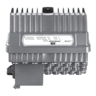
Drive Technology \ Drive Automation \ System Integration \ Services ® MOVIFIT Operating Instructions Edition 10/2008 11663014 / EN... - Page 2 SEW-EURODRIVE – Driving the world...
- Page 3 Contents 1 General Information ....................5 Use of operating instructions................5 Structure of the safety notes ................5 Rights to claim under warranty............... 6 Exclusion of liability ..................6 Copyright......................6 2 Safety Notes ......................7 General information ..................7 Target group ....................
- Page 4 Contents 6 Startup........................97 Startup instructions ..................97 ® Startup procedure for MOVIFIT -FC ............99 ® Startup MOVIFIT ..................100 ® Startup MOVIFIT frequency inverter ............104 7 Operation ......................111 ® Status LEDs for MOVIFIT -FC ..............111 Manual operation using the DBG keypad ..........
-
Page 5: General Information
General Information Use of operating instructions General Information Use of operating instructions The operating instructions are an integral part of the product and contain important information for operation and service. The operating instructions are written for all employees who assemble, install, start up, and service this product. The operating instructions must be kept available in a legible condition. -
Page 6: Rights To Claim Under Warranty
General Information Rights to claim under warranty Rights to claim under warranty Adhering to the operating instructions is a prerequisite for fault-free operation and the fulfillment of any right to claim under warranty. You should therefore read the operating instructions before you start working with the unit. Make sure that the operating instructions are available to persons responsible for the plant and its operation as well as to persons who work independently on the unit. -
Page 7: Safety Notes
Safety Notes General information Safety Notes The following basic safety notes are intended to prevent injury to persons and damage to property. The operator must ensure that the basic safety notes are observed and complied with. Ensure that persons responsible for the system and its operation as well as persons who work independently on the unit have read through the operating instruc- tions carefully and understood them. -
Page 8: Designated Use
Safety Notes Designated use Designated use ® MOVIFIT -FC is a component intended for installation in electrical systems or machines. ® ® When MOVIFIT -FC is installed in machines, startup of the MOVIFIT -FC (i.e., start of designated operation) is prohibited until it is determined that the machine meets the requirements stipulated in EC directive 98/37/EC (Machine directive). -
Page 9: Transportation And Storage
Safety Notes Transportation and storage Transportation and storage Observe the notes on transportation, storage and proper handling. Observe the climatic conditions as stated in the "Technical Data" sections. Installation The units must be installed and cooled according to the regulations in the relevant documentation. -
Page 10: Operation
Safety Notes Operation Operation ® Systems into which MOVIFIT -FC is installed may also need to be equipped with addi- tional monitoring and protection devices, according to the applicable safety regulations; these include the law governing technical equipment and accident prevention regula- tions. -
Page 11: Unit Design
Unit Design Overview Unit Design Overview 3.1.1 Combinations in connection with standard ABOX and hybrid ABOX ® The following figure shows the MOVIFIT versions described in these operating instruc- tions using the standard ABOX and hybrid ABOX. EBOX ABOX Version MTA...-S02.-...-0 Standard ABOX with terminals and cable bushings... - Page 12 Unit Design Overview ® 3.1.2 Combinations in connection with Han-Modular -ABOX ® The figure that follows shows the MOVIFIT versions described in these operating ® instructions with the Han-Modular -ABOX. EBOX ABOX MTA...-H12.-...-00 MTF...-...-00 Size 1 ® Han-Modular -ABOX with M12 for I/Os and bus and with industrial plug connectors MTA...-H22.-...-00 Size 2...
-
Page 13: Ebox (Active Electronics Unit)
Unit Design EBOX (active electronics unit) EBOX (active electronics unit) ® The MOVIFIT -FC EBOX is a closed electronics unit with a communication interface, I/Os, and a frequency inverter: EBOX " MTF...-..-00" 1 2 3 4 5 6 812522763 Size 1 Size 2 Central opening/closing mechanism Operation LEDs for I/Os (can be labeled), communication, and unit status... -
Page 14: Abox (Passive Connection Unit)
Unit Design ABOX (passive connection unit) ABOX (passive connection unit) 3.3.1 Standard ABOX and hybrid ABOX ® ® The following figure gives an example of the MOVIFIT standard ABOX/MOVIFIT hybrid ABOX: ABOX "MTA...-S02.-...-00" ABOX "MTA...-S42.-...-00" ABOX "MTA...-S52.-...-00" ABOX "MTA...-S62.-...-00" [10] 812524427 Mounting rail Connection to EBOX... - Page 15 Unit Design ABOX (passive connection unit) ® 3.3.2 Han-Modular -ABOX ® ® The following figure depicts the Han-Modular connection box with Han-Modular M12 plug connector: The figure below shows an example of the connection technology of the PROFIBUS version. For more detailed information on other variants, refer to section "Electrical Installation".
-
Page 16: Hygienicplus Version (Optional)
Unit Design Hygienicplus version (optional) plus Hygienic version (optional) 3.4.1 Properties plus The Hygienic version has the following characteristics: • IP66 in accordance with EN 60529 and IP69K in accordance with DIN 40050-9 ® (MOVIFIT housing closed and all cable bushings sealed according to the relevant degree of protection) •... - Page 17 Unit Design Hygienicplus version (optional) ® The following figure depicts the additional features of MOVIFIT units in the optional plus Hygienic version: EBOX " MTF12...-..-00" ABOX "MTA12...-S02.-...-00" [10] [11] 812491147 EBOX with special surface treatment (only available in one color) Signal plug connector with gasket Gasket between ABOX and coverplate Power plug connector with gasket...
-
Page 18: Movifit ® -Fc Unit Designation
Unit Design MOVIFIT®-FC unit designation ® MOVIFIT -FC unit designation 3.5.1 Sample EBOX nameplate External nameplate EBOX status field 812579339 Internal nameplate Firmware status MT F 11 A 015- 50 3 - P1 0 A - 00 / S11 EBOX option S11 = PROFIsafe option S11 EBOX version 00 = DT/DV motor 400 V, 50 Hz... - Page 19 Unit Design MOVIFIT®-FC unit designation 3.5.2 Sample ABOX nameplate 812581003 [1] ABOX status field MT A 11 A - 50 3 -S02 1 - D 01 - 00 / BW1 ABOX option BW1 / BW2 = Integrated braking resistor M11 = Stainless steel mounting rail ABOX version 00 = Series Maintenance switch type...
-
Page 20: Mechanical Installation
Mechanical Installation Installation instructions Mechanical Installation Installation instructions ® • Mount MOVIFIT only on a level, vibration-proof and torsionally rigid support struc- ture, as described in the section "Approved installation position". • Use suitable cable glands (use reducing adapters if necessary). For versions with plug connectors, make sure to use the matching mating connectors. -
Page 21: Assembly Instructions
Mechanical Installation Assembly instructions Assembly instructions 1. Drill the holes necessary to secure at least four screws to the mounting surface as shown in the following figure. SEW-EURODRIVE recommends using screw size M6 and, depending on the base, suitable dowel pins, if necessary. Size 1 In conjunction with a standard mounting rail: min. - Page 22 Mechanical Installation Assembly instructions Size 1 In conjunction with the optional M11 stainless steel mounting rail: min. 50 334.4 799309835 TIPS • [1] Observe the minimum installation clearance so that the EBOX can be removed from the ABOX. • [2] Observe the minimum installation clearance required to operate the mainte- nance switch and to ensure heat dissipation for the unit.
- Page 23 Mechanical Installation Assembly instructions Size 2: min. 50 334.5 812584331 TIPS • [1] Observe the minimum installation clearance so that the EBOX can be removed from the ABOX. • [2] Observe the minimum installation clearance required to operate the mainte- nance switch and to ensure heat dissipation for the unit.
- Page 24 Mechanical Installation Assembly instructions 2. Mount at least 4 screws on the mounting surface. SEW-EURODRIVE recommends using screw size M6 and, depending on the base, dowel pins, if necessary. Use appropriate washers or screw and washer assemblies for the mounting plates plus with special surface treatment on the Hygienic version.
- Page 25 Mechanical Installation Assembly instructions 4. Tighten the screws. CAUTION Danger due to falling load Minor injuries • You will have to tighten at least 4 wall screws to ensure a secure fit after mounting. 758590731 ® Operating Instructions – MOVIFIT...
-
Page 26: Central Opening/Closing Mechanism
Mechanical Installation Central opening/closing mechanism Central opening/closing mechanism WARNING ® The surface temperature of the MOVIFIT -FC can be very high during operation. Danger of burns ® • Do not touch MOVIFIT -FC until it has cooled down sufficiently. NOTICE If the torque is too high, the central opening/closing mechanism can be destroyed. - Page 27 Mechanical Installation Central opening/closing mechanism 4.4.2 Closing the unit A socket wrench (SW8) is required for the central retaining screw. 1. Position the EBOX on the ABOX. – Do not twist the EBOX. – Hold the EBOX only by both sides during the procedure (see the following figure). 90°...
-
Page 28: Tightening Torques
Mechanical Installation Tightening torques Tightening torques 4.5.1 Blanking plugs Tighten the blanking plugs optionally supplied by SEW-EURODRIVE using a tightening torque of 2.5 Nm (22 lb.in): 758614667 ® Operating Instructions – MOVIFIT... - Page 29 Mechanical Installation Tightening torques 4.5.2 EMC cable glands Tighten the EMC cable glands optionally supplied by SEW-EURODRIVE to the following torques: 758624523 Screw connection Part number Size Tightening torque EMC cable glands 1820 478 3 M16 x 1.5 3.5 Nm to 4.5 Nm (31-40 lb.in) (nickel-plated brass) 1820 479 1 M20 x 1.5...
-
Page 30: Movifit ® Hygienicplus Version
Mechanical Installation MOVIFIT® Hygienicplus version ® plus MOVIFIT Hygienic version TIPS plus SEW-EURODRIVE guarantees that the Hygienic special surface treatment is free from faults when delivered. Report any damage that has occurred during transport immediately. Although the special surface treatment has a high impact resistance, the housing surfaces are to be handled with care. - Page 31 Mechanical Installation MOVIFIT® Hygienicplus version plus 4.6.2 Tightening torques for Hygienic version CAUTION The IP69K degree of protection is achieved only if the plastic screw plugs delivered as standard are replaced by suitable IP69K screw connections. Refer to section "Optional metal screw connections" (see page 145) for screw connec- tions available from SEW-EURODRIVE.
- Page 32 Mechanical Installation MOVIFIT® Hygienicplus version EMC cable glands Tighten the EMC cable glands optionally supplied by SEW-EURODRIVE to the following torques: 512772875 Screw connection Part number Size Tightening torque EMC cable glands 1820 478 3 M16 x 1.5 3.0 Nm to 4.0 Nm (26-35 lb.in) (nickel-plated brass) 1820 479 1 M20 x 1.5...
-
Page 33: Electrical Installation
Electrical Installation Installation planning taking into account EMC aspects Electrical Installation Installation planning taking into account EMC aspects Successful installation of decentralized drives depends on selecting the correct cables, providing correct grounding, and a functioning equipotential bonding. Always apply the relevant standards. Consider the following points: •... -
Page 34: Installation Instructions (All Versions)
Electrical Installation Installation instructions (all versions) Installation instructions (all versions) 5.2.1 Connecting supply system cables ® • The rated voltage and frequency of the MOVIFIT frequency inverter must match the data for the supplying mains. • Cable cross section: According to input current I for rated power (see Technical mains Data) - Page 35 Electrical Installation Installation instructions (all versions) 5.2.4 Notes on PE connection and/or equipotential bonding DANGER Incorrect connection of PE Severe or fatal injuries or damage to property from electric shock • The permitted tightening torque for the screw connection is 2.0-2.4 Nm (18-21 lb.in). •...
- Page 36 Electrical Installation Installation instructions (all versions) 5.2.5 Definition PE, FE • PE refers to the mains-side protective earth connection. The PE conductor in the mains connection cable may only be connected with terminals marked with "PE" (these are designed for the maximum permissible mains connection cross-section). •...
- Page 37 Electrical Installation Installation instructions (all versions) 5.2.6 Meaning of the 24 V voltage levels ® MOVIFIT -FC has a total of 4 different 24 V potential levels, each electrically isolated from the others: • 1) 24V_C: C = Continuous • 2) 24V_S: S = Switched •...
- Page 38 Electrical Installation Installation instructions (all versions) 4) 24V_O = Option The integrated option card and the sensor/actuator interfaces available on it are sup- supply plied by 24V_O. With PROFIsafe option S11, the complete safety electronics and the safe inputs/outputs are supplied by 24V_O. DANGER When using PROFIsafe option S11, please observe the SEW publication "Safe Discon- ®...
- Page 39 Electrical Installation Installation instructions (all versions) 5.2.7 Plug connectors ® All MOVIFIT plug connectors are illustrated in these operating instructions with a con- tact end view. 5.2.8 Operating braking resistors The supply cables to the braking resistors carry a high pulsed DC voltage during rated operation.
- Page 40 Electrical Installation Installation instructions (all versions) 5.2.11 UL-compliant installation • Use only copper conductors with a temperature range of 75°C as connection cables. ® • MOVIFIT -FC is designed for operation on voltage supply systems with a maximum supply current of AC 5,000 A and a maximum rated voltage of AC 500 V. ®...
- Page 41 Electrical Installation Installation instructions (all versions) 5.2.13 Wiring check Before connecting the system to the power source for the first time, you must perform a wiring check to prevent injuries to persons and/or damage to systems and equipment caused by incorrect wiring. Perform this check as follows: •...
-
Page 42: Additional Installation Instructions For Group Drives
Electrical Installation Additional installation instructions for group drives Additional installation instructions for group drives The following figure shows the prescribed installation for group drives with ® MOVIFIT -FC: ® MOVIFIT 1240954123 When installing such group drives, also follow the installation instructions below: ®... -
Page 43: Standard Abox "Mta...-S02.-...-00
Electrical Installation Standard ABOX "MTA...-S02.-...-00" Standard ABOX "MTA...-S02.-...-00" 5.4.1 Description The following figure depicts the standard ABOX with "MTA...-S02.-...-00" terminals and cable bushings: 812547723 Maintenance switch (option) PE connection Diagnostics socket (RJ10) under the screw connection ® Operating Instructions – MOVIFIT... - Page 44 Electrical Installation Standard ABOX "MTA...-S02.-...-00" 5.4.2 Variants ® The following variants of the standard ABOX are available for MOVIFIT -FC (MTF): • MTA11A-503-S02.-...-00: – Optional external braking resistor – Optional integrated braking resistor – Optional switch disconnector The following figure shows the screw connections and plug connectors of the standard ABOX depending on the fieldbus interface: MTA11A-503-S0.1-...-00 PROFIBUS...
- Page 45 Electrical Installation Standard ABOX "MTA...-S02.-...-00" 5.4.3 Additional installation instructions for "MTA...-S02.-...-00" Permitted connection cross section and current-carrying capacity of the terminals Terminal data X1 / X20 X8 / X9 X25 / X30 / X31 / X35 / X45 / X81 / X91 Connection cross 0.2 mm –...
- Page 46 Electrical Installation Standard ABOX "MTA...-S02.-...-00" Enabling the terminals Terminals X1, X20 Connecting conductors without a screw driver Connecting conductors using a screw driver 812407947 812406283 1) Single-wire conductors and flexible conductors with conductor end sleeves can be installed directly (without using a tool) up to two cross section sizes below the rated cross section. 2) When connecting untreated, flexible conductors or conductors with a small cross section that cannot be installed directly, firmly insert a screw driver into the activation opening to open the clamping spring.
- Page 47 Electrical Installation Standard ABOX "MTA...-S02.-...-00" Connection of the Observe the following guidelines compiled by the PROFIBUS Nutzerorganisation e.V. PROFIBUS cable (PROFIBUS user organization) when installing the PROFIBUS (on the Internet at ® in MOVIFIT www.profibus.com): • "Installation guidelines for PROFIBUS DP/FMS", order number 2.111 (German) or 2.112 (English) •...
- Page 48 Electrical Installation Standard ABOX "MTA...-S02.-...-00" Connecting the • SEW-EURODRIVE recommends using the shielded and pre-fabricated SEW hybrid ® hybrid cable cables specifically designed for connecting MOVIFIT and the motor; see the section "Hybrid cables" (see page 92). • The outer shield of the hybrid cable must be attached to the housing of the unit using a suitable EMC cable gland.
- Page 49 Electrical Installation Standard ABOX "MTA...-S02.-...-00" 5.4.4 Fieldbus/option-independent terminal assignment DANGER The maintenance switch only disconnects the integrated frequency inverter from the ® mains. Voltage is still present on the terminals of the MOVIFIT unit. Severe or fatal injuries from electric shock ®...
- Page 50 Electrical Installation Standard ABOX "MTA...-S02.-...-00" 2 3 4 5 6 11 1 12 12 13 13 14 1415 15 16 1718 2 3 4 1 2 3 4 11 12 13 14 1 2 3 4 5 1 2 3 4 5 6 7 8 12 13 14 15 12 13 14 1516 17 18 2 3 4...
- Page 51 Electrical Installation Standard ABOX "MTA...-S02.-...-00" 2 3 4 5 6 11 1 12 12 13 13 14 1415 15 16 1718 2 3 4 1 2 3 4 11 12 13 14 1 2 3 4 5 1 2 3 4 5 6 7 8 12 13 14 15 12 13 14 1516 17 18 2 3 4...
- Page 52 Electrical Installation Standard ABOX "MTA...-S02.-...-00" 2 3 4 5 6 11 12 13 1415 16 1718 2 3 4 1 2 3 4 11 12 13 14 1 2 3 4 5 1 2 3 4 5 6 7 8 12 13 14 15 12 13 14 1516 17 18 2 3 4...
- Page 53 Electrical Installation Standard ABOX "MTA...-S02.-...-00" 2 3 4 5 6 11 1 12 12 13 13 14 1415 15 16 1718 2 3 4 1 2 3 4 11 12 13 14 1 2 3 4 5 1 2 3 4 5 6 7 8 12 13 14 15 12 13 14 1516 17 18 2 3 4...
- Page 54 Electrical Installation Standard ABOX "MTA...-S02.-...-00" 2 3 4 5 6 11 1 12 12 13 13 14 1415 15 16 1718 2 3 4 1 2 3 4 11 12 13 14 1 2 3 4 5 1 2 3 4 5 6 7 8 12 13 14 15 12 13 14 1516 17 18 2 3 4...
- Page 55 Electrical Installation Standard ABOX "MTA...-S02.-...-00" 2 3 4 5 6 11 1 12 12 13 13 14 1415 15 16 1718 2 3 4 1 2 3 4 11 12 13 14 1 2 3 4 5 1 2 3 4 5 6 7 8 12 13 14 15 12 13 14 1516 17 18 2 3 4...
- Page 56 Electrical Installation Standard ABOX "MTA...-S02.-...-00" 5.4.5 Option-dependent terminal assignment I/O terminal X45 in conjunction with PROFIsafe option card S11 2 3 4 5 6 11 1 12 12 13 13 14 1415 15 16 1718 2 3 4 1 2 3 4 11 12 13 14 1 2 3 4 5 1 2 3 4 5 6 7 8...
- Page 57 Electrical Installation Standard ABOX "MTA...-S02.-...-00" 5.4.6 Fieldbus-dependent terminal/pin assignment PROFIBUS terminal assignment 1 2 3 2 3 4 5 6 11 1 12 12 13 13 14 1415 15 16 1718 2 3 4 1 2 3 4 11 12 13 14 1 2 3 4 5 1 2 3 4 5 6 7 8 1 2 3...
- Page 58 Electrical Installation Standard ABOX "MTA...-S02.-...-00" Pin assignment for EtherNet/IP, PROFINET, and Modbus/TCP 2 3 4 5 6 11 1 12 12 13 13 14 1415 15 16 1718 2 3 4 1 2 3 4 11 12 13 14 1 2 3 4 5 1 2 3 4 5 6 7 8 12 13 14 15 12 13 14 1516 17 18...
- Page 59 Electrical Installation Standard ABOX "MTA...-S02.-...-00" DeviceNet terminal/pin assignment 2 3 4 5 6 11 1 12 12 13 13 14 1415 15 16 1718 1 2 3 4 5 2 3 4 1 2 3 4 11 12 13 14 1 2 3 4 5 1 2 3 4 5 6 7 8 12 13 14 15...
-
Page 60: Hybrid Abox "Mta...-S42.-...-00
Electrical Installation Hybrid ABOX "MTA...-S42.-...-00" Hybrid ABOX "MTA...-S42.-...-00" • The hybrid ABOX is based on the standard ABOX "MTA...-S02.-...-00". Therefore, the following describes only the additional plug connectors in comparison with the standard ABOX. • For a description of the terminals, refer to section "Standard ABOX "MTA...-S02.- ...00"... - Page 61 Electrical Installation Hybrid ABOX "MTA...-S42.-...-00" Y adapter Use a Y adapter with an extension for connecting two sensors/actuators to an M12 plug connector. The Y adapter is available from various manufacturers: Manu- Escha facturer: Type: WAS4-0,3-2FKM3/.. 915294347 Manu- Binder facturer: Type: 79 5200 ..
- Page 62 Electrical Installation Hybrid ABOX "MTA...-S42.-...-00" 5.5.2 Variants ® The following variants of the hybrid ABOX are available for MOVIFIT -FC (MTF): • MTA11A-503-S42.-...-00: – Optional external braking resistor – Optional integrated braking resistor – Optional switch disconnector The following figure shows the screw connections and plug connectors of the hybrid ABOX: MTA11A-503-S4.1-...-00 PROFIBUS...
- Page 63 Electrical Installation Hybrid ABOX "MTA...-S42.-...-00" 5.5.3 I/O pin assignment (X21-X28) I/Os 12 DI + 4 DI/O (Encoder 1 (Encoder 2 connection) connection) M12 plug connector, VO24-I VO24-I VO24-II VO24-II standard coding, female DI01 DI03 DI05 DI07 Encoder track B Encoder track B 0V24_C 0V24_C 0V24_C...
-
Page 64: Hybrid Abox "Mta...-S52.-...-00
Electrical Installation Hybrid ABOX "MTA...-S52.-...-00" Hybrid ABOX "MTA...-S52.-...-00" • The hybrid ABOX is based on the standard ABOX "MTA...-S02.-...-00". Therefore, the following describes only the additional plug connectors in comparison with the standard ABOX. • For a description of the terminals, refer to section "Standard ABOX "MTA...-S02.-...- 00""... - Page 65 Electrical Installation Hybrid ABOX "MTA...-S52.-...-00" Y adapter Use a Y adapter with an extension for connecting two sensors/actuators to an M12 plug connector. The Y adapter is available from various manufacturers: Manu- Escha facturer: Type: WAS4-0,3-2FKM3/.. 915294347 Manu- Binder facturer: Type: 79 5200 ..
- Page 66 Electrical Installation Hybrid ABOX "MTA...-S52.-...-00" 5.6.2 Variants ® The following variants of the hybrid ABOX are available for MOVIFIT -FC (MTF): • MTA11A-503-S52.-...-00: – Optional external braking resistor – Optional integrated braking resistor – Optional switch disconnector The following figure shows the screw connections and plug connectors of the hybrid ABOX depending on the fieldbus interface: MTA11A-503-S5.1-...-00 M12, B coding,...
- Page 67 Electrical Installation Hybrid ABOX "MTA...-S52.-...-00" 5.6.3 Pin assignment of fieldbus interface (X11/X12) PROFIBUS X11 (PROFIBUS IN) Assignment X12 (PROFIBUS OUT) Assignment M12 plug connector, B n.c. M12 plug connector, B +5V_PB coding, male coding, female A_IN A_OUT n.c. 0V5_PB B_IN B_OUT n.c.
- Page 68 Electrical Installation Hybrid ABOX "MTA...-S52.-...-00" 5.6.4 I/O pin assignment (X21-X28) I/Os 12 DI + 4 DI/O (Encoder 1 (Encoder 2 connection) connection) M12 plug connector, VO24-I VO24-I VO24-II VO24-II standard coding, female DI01 DI03 DI05 DI07 Encoder track B Encoder track B 0V24_C 0V24_C 0V24_C...
-
Page 69: Hybrid Abox "Mta...-S62.-...-00
Electrical Installation Hybrid ABOX "MTA...-S62.-...-00" Hybrid ABOX "MTA...-S62.-...-00" • The hybrid ABOX is based on the standard ABOX "MTA...-S02.-...-00". Therefore, the following describes only the additional plug connectors in comparison with the standard ABOX. • For a description of the terminals, refer to section "Standard ABOX "MTA...-S02.- ...00""... - Page 70 Electrical Installation Hybrid ABOX "MTA...-S62.-...-00" Y adapter Use a Y adapter with an extension for connecting two sensors/actuators to an M12 plug connector. The Y adapter is available from various manufacturers: Manu- Escha facturer: Type: WAS4-0,3-2FKM3/.. 915294347 Manu- Binder facturer: Type: 79 5200 ..
- Page 71 Electrical Installation Hybrid ABOX "MTA...-S62.-...-00" 5.7.2 Variants ® The following variants of the hybrid ABOX are available for MOVIFIT -FC (MTF): • MTA11A-503-S62.-...-00: – Optional external braking resistor – Optional integrated braking resistor – Optional switch disconnector The following figure shows the screw connections and plug connectors of the hybrid ABOX: MTA11A-503-S6.3-...-00 PROFINET...
- Page 72 Electrical Installation Hybrid ABOX "MTA...-S62.-...-00" 5.7.4 I/O pin assignment (X21-X28) I/Os 12 DI + 4 DI/O (Encoder 1 (Encoder 2 connection) connection) M12 plug connector, VO24-I VO24-I VO24-II VO24-II standard coding, female DI01 DI03 DI05 DI07 Encoder track B Encoder track B 0V24_C 0V24_C 0V24_C...
-
Page 73: Han-Modular ® -Abox "Mta...-H12.-...-00", "Mta...-H22.-...-00
Electrical Installation Han-Modular®-ABOX "MTA...-H12.-...-00", "MTA...-H22.-...-00" ® Han-Modular -ABOX "MTA...-H12.-...-00", "MTA...-H22.-...-00" 5.8.1 Description ® ® The following figure shows the Han-Modular -ABOX for MOVIFIT -FC depending on the fieldbus interface: PROFIBUS MTA11A-503-H121-...-00 [12] [11] [10] PROFINET Ethernet/IP DeviceNet MTA11A-503-H223-...-00 MTA11A-503-H122-...-00 936437515 M12 plug connector for I/Os M23 plug connector (12-pin) for I/O extension box SBus (CAN) - Page 74 Electrical Installation Han-Modular®-ABOX "MTA...-H12.-...-00", "MTA...-H22.-...-00" 5.8.2 Variants ® ® The following variants of the Han-Modular -ABOX are available for MOVIFIT (MTF): • MTA11A-503-H22.-...-00, MTA11A-503-H12.-...-00: – Optional external braking resistor – Optional integrated braking resistor – Switch disconnector integrated as standard 5.8.3 Power bus pin assignment (X1) Power bus...
- Page 75 Electrical Installation Han-Modular®-ABOX "MTA...-H12.-...-00", "MTA...-H22.-...-00" 5.8.4 Pin assignment of motor (X8) Motor ® ® Han-Modular Compact with Han TF+_M1 module, socket insert, female 13_M1 U_M1 W_M1 TF-_M1 14_M1 15_M1 V_M1 PE_M1 SEW-EURODRIVE recommends using the shielded and pre-fabricated SEW hybrid ®...
- Page 76 Electrical Installation Han-Modular®-ABOX "MTA...-H12.-...-00", "MTA...-H22.-...-00" 5.8.6 24 V distributor terminal assignment for the integrated frequency inverter and the option card (X29) 1 2 3 4 5 7 8 9 812487819 24 V distributor terminal (for distributing the supply voltage(s) to the integrated frequency inverter and the option card) Name Function +24V_C...
- Page 77 Electrical Installation Han-Modular®-ABOX "MTA...-H12.-...-00", "MTA...-H22.-...-00" 5.8.7 Pin assignment of fieldbus interface Ethernet (PROFINET, EtherNet/IP, or Modbus/TCP) X11 (Port1) Assignment X12 (Port2) Assignment Push-pull RJ45 plug Push-pull RJ45 plug connector connector TX– TX– Res. Res. Res. Res. RX– RX– Res. Res. Res.
- Page 78 Electrical Installation Han-Modular®-ABOX "MTA...-H12.-...-00", "MTA...-H22.-...-00" 5.8.8 I/O pin assignment (X21-X28/X19/X41-X44) I/Os 12 DI + 4 DI/O (Encoder 1 (Encoder 2 connection) connection) M12 plug connector, VO24-I VO24-I VO24-II VO24-II standard coding, female DI01 DI03 DI05 DI07 Encoder track B Encoder track B 0V24_C 0V24_C 0V24_C...
- Page 79 Electrical Installation Han-Modular®-ABOX "MTA...-H12.-...-00", "MTA...-H22.-...-00" I/O expansion (as an alternative for standard I/Os) ® Can only be used in connection with MOVIFIT versions with 12 DI + 4 DI/O Assignment M23 plug connector DI01 (female) DI03 DI05 DI07 DI09 DI11 DI13/DO01 DI15/DO03 0V24_C...
-
Page 80: Power Bus Connection Examples
Electrical Installation Power bus connection examples Power bus connection examples 5.9.1 Power bus in conjunction with terminal connection The examples are valid for the following connection boxes: • Standard ABOX "MTA...-S02.-...-00" • Hybrid ABOX "MTA...-S42.-...-00" • Hybrid ABOX "MTA...-S52.-...-00" • Hybrid ABOX "MTA...-S62.-...-00"... - Page 81 Electrical Installation Power bus connection examples Connection The following figure depicts a basic connection example for the power bus with two example with two separate 24 V voltage circuits for sensor/actuator supply. In the example, the integrated separate 24 V frequency inverter is supplied by the voltage 24V_C: voltage circuits 3 4 11 12 13 14...
- Page 82 Electrical Installation Power bus connection examples ® 5.9.2 Power bus with Han-Modular plug connector This example applies for the following connection box: ® • Han-Modular -ABOX "MTA...-H12.-...-00" ® • Han-Modular -ABOX "MTA...-H22.-...-00" Power distribution • SEW-EURODRIVE recommends using HARTING Power S products for power bus and line protection project planning.
- Page 83 Electrical Installation Power bus connection examples Inverter supply The following figure shows an example of the wiring of the X29 terminal for supplying the integrated frequency inverter from 24V_C: 1 2 3 4 5 7 8 9 812489483 ® Operating Instructions – MOVIFIT...
-
Page 84: Fieldbus Systems Connection Examples
Electrical Installation Fieldbus systems connection examples 5.10 Fieldbus systems connection examples 5.10.1 PROFIBUS Via terminals The example applies for the following connection box: • Standard ABOX "MTA...-S02.-...-00" • Hybrid ABOX "MTA...-S42.-...-00" The following figure shows the PROFIBUS connection via terminals: ®... - Page 85 Electrical Installation Fieldbus systems connection examples Via M12 plug connectors The example applies for the following connection boxes: • Hybrid ABOX "MTA...-S52.-...-00" ® • Han-Modular -ABOX "MTA...-H12.-...-00" The following figure depicts the basic connection topology for PROFIBUS using M12 ® plug connectors (the example shows a Han-Modular -ABOX): •...
- Page 86 Electrical Installation Fieldbus systems connection examples 5.10.2 PROFINET / EtherNet/IP The example applies for the following connection boxes: • Standard ABOX "MTA...-S02.-...-00" • Hybrid ABOX "MTA...-S42.-...-00" • Hybrid ABOX "MTA...-S52.-...-00" • Hybrid ABOX "MTA...-S62.-...-00" ® • Han-Modular -ABOX "MTA...-H22.-...-00" The following figure depicts the basic connection topology for PROFINET (using a hybrid ABOX as an example): ®...
- Page 87 Electrical Installation Fieldbus systems connection examples 5.10.3 DeviceNet The example applies for the following connection boxes: • Standard ABOX "MTA...-S02.-...-00" • Hybrid ABOX "MTA...-S52.-...-00" ® • Han-Modular -ABOX "MTA...-H12.-...-00" The following figure shows the basic connection topology for DeviceNet using a micro- style connector (the example depicts an ABOX with terminals and cable bushings): •...
-
Page 88: Encoder Connection
Electrical Installation Encoder connection 5.11 Encoder connection 5.11.1 Connecting the NV26 proximity sensor Properties The NV26 proximity sensor offers the following features: • 2 sensors with 6 pulses/revolution • 24 increments/revolution with 4-fold evaluation ® • Encoder monitoring and evaluation is possible with MOVIFIT function level "Technology". - Page 89 Electrical Installation Encoder connection 5.11.2 Connecting the incremental encoder ES16 Properties The ES 16 incremental encoder offers the following features: • 6 pulses/revolution for each track • 24 increments/revolution with 4-fold evaluation ® • Encoder monitoring and evaluation is possible with MOVIFIT function level "Technology".
- Page 90 Electrical Installation Encoder connection 5.11.3 Connecting the incremental encoder EI7. Properties The E17. incremental encoder offers the following features: ® • HTL or sin/cos interface (MOVIFIT does not evaluate sin/cos signals) EI71: 1 pulse/revolution => 4 increments/revolution EI72: 2 pulses/revolution =>...
-
Page 91: Pc Connection
Electrical Installation PC connection 5.12 PC connection 5.12.1 Diagnostic interface ® MOVIFIT units have an X50 diagnostic interface (RJ10 plug connector) for startup, parameter setting, and servicing. MTA...-S42.-...-00 MTA...-H12.-...-00 MTA...-S02.-...-00 MTA...-S52.-...-00 MTA...-H22.-...-00 MTA...-S62.-...-00 812561035 Depending on the function level used, different functions are available. These are described in the corresponding manuals. -
Page 92: Hybrid Cables
Electrical Installation Hybrid cables 5.13 Hybrid cables 5.13.1 Overview ® Hybrid cables are available for connecting MOVIFIT -FC and motors. The following table provides an overview of the available hybrid cables: ® MOVIFIT Hybrid cables Length Cable Drive type Standard ABOX: Part no. -
Page 93: Operating Instructions – Movifit ® -Fc
Electrical Installation Hybrid cables ® MOVIFIT Hybrid cables Length Cable Drive type ® Han-Modular -ABOX: Part number: 1810 096 1 Variable Motor with ASB4 (BA01AB04DA) plug MTA...-H12.-...-00 connector MTA...-H22.-...-00 Part number: 1810 098 8 Variable Motor with plug connector AMB4 (MA01AB04DA) Part number: 1810 099 6 Variable Motor with APG4 plug... - Page 94 Electrical Installation Hybrid cables 5.13.2 Connecting hybrid cables With open cable The table shows the assignment of the following hybrid cables: ® end (MOVIFIT • Part number 0819 967 1 side) and plug connector 0819 969 8 (motor side) 0819 970 1 0819 874 8 •...
- Page 95 Electrical Installation Hybrid cables With open cable The table shows the assignment of the following hybrid cables: ® end (MOVIFIT • Part number 0819 975 2 and motor side) • Part number 0 818 736 3 • Part number 0 818 739 8 ®...
- Page 96 Electrical Installation Hybrid cables With plug The table shows the assignment of the following hybrid cables: connector • Part number 1811 121 1 ® (MOVIFIT side) and open cable 1811 128 9 end (motor side) Hybrid cables Connection terminal Color coding/marking Motor Green/yellow PE terminal...
-
Page 97: Startup
Startup Startup instructions Startup Startup instructions DANGER You must disconnect the units from the mains before removing or installing the ® MOVIFIT -EBOX. Dangerous voltages may still be present for up to one minute after disconnection from the power supply. Severe or fatal injuries from electric shock ®... - Page 98 Startup Startup instructions 6.1.1 Wiring notes for connecting the motor • Motor phases U, V, and W must be connected correctly in accordance with the motor ® connection terminals in MOVIFIT . This ensures that the motor rotates in the correct direction.
-
Page 99: Startup Procedure For Movifit ® -Fc
Startup Startup procedure for MOVIFIT®-FC ® Startup procedure for MOVIFIT ® The following section describes how to start up MOVIFIT -FC. Depending on the ® MOVIFIT function level, note additional documentation for fieldbus configuration and advanced startup/parameter setting. ® The following tables provide an overview of MOVIFIT -FC startup and refer to additional publications: ®... -
Page 100: Startup Movifit
Startup Startup MOVIFIT® ® Startup MOVIFIT 6.3.1 Startup in conjunction with PROFIBUS ® 1. Check the MOVIFIT connection. ® 2. Set the PROFIBUS address at DIP switch S2 of the MOVIFIT -ABOX, see section "ABOX" (see page 14). Use DIP switches 1 to 7 to set the PROFIBUS address. x 0 = x 0 = x 1 = 16... - Page 101 Startup Startup MOVIFIT® ® ® 4. To start up the MOVIFIT frequency inverter, see the section "Startup MOVIFIT Frequency Inverter" (see page 104). ® 5. Mount the MOVIFIT -EBOX on the ABOX and close it. 6. Switch on the 24V_C and 24V_S supply voltage(s). The associated control LEDs should now light up green.
- Page 102 Startup Startup MOVIFIT® 6.3.2 Startup with PROFINET IO, EtherNet/IP, or Modbus/TCP ® 1. Check the MOVIFIT connection. In conjunction with PROFINET IO, EtherNet/IP, or Modbus/TCP, you do not have to ® make any settings on the MOVIFIT for fieldbus startup. The entire fieldbus startup is carried out via Software Tools and is described in the applicable manuals: ®...
- Page 103 Startup Startup MOVIFIT® 6.3.3 Startup with DeviceNet ® 1. Check the MOVIFIT connection. ® 2. Set the DeviceNet address at DIP switch S2 of the MOVIFIT -ABOX. ® 3. Set the baud rate at DIP switch S2 of the MOVIFIT -ABOX: ®...
-
Page 104: Startup Movifit ® Frequency Inverter
Startup Startup MOVIFIT® frequency inverter ® Startup MOVIFIT frequency inverter 6.4.1 Startup mode ® You can use one of the following startup modes to start up the MOVIFIT frequency inverter: ® • MOVIFIT -FC can be put into operation quickly and easily in "Easy" mode using DIP switch S10 (see section "EBOX", page 13). - Page 105 Startup Startup MOVIFIT® frequency inverter Description of DIP In Easy mode, the unit parameters are set using the DIP switches S10/2 to S10/6. switches S10/2 to The following sections describe the setting options: S10/6 837604491 Meaning Startup Operating Motor/brake Motor Motor Hoist mode...
- Page 106 Startup Startup MOVIFIT® frequency inverter DIP switch S10/5 Lower motor power rating ® • When activated, this DIP switch enables MOVIFIT to be assigned to a motor with a lower power rating. The rated unit power is not affected. • When a motor with a lower power rating is used, the overload capacity of the drive ®...
- Page 107 Startup Startup MOVIFIT® frequency inverter V = AC 3 x 400 V, 50 Hz or AC 3 x 460 V, 60 Hz ® MOVIFIT Assigned DRS motor and brake S10/5 = OFF S10/5 = ON Õ connection Ö connection Õ connection Ö...
- Page 108 Startup Startup MOVIFIT® frequency inverter V = A C 3 x 400 V, 50 Hz ® MOVIFIT Assigned DRP motor and brake S10/5 = OFF S10/5 = ON Õ connection Ö connection Õ connection Ö connection Motor Brake Motor Brake Motor Brake Motor...
- Page 109 Startup Startup MOVIFIT® frequency inverter DIP switch S10/6 Hoist application • DIP switch S10/6 = OFF: The operating mode is selected according to DIP switch S10/2. ® • DIP switch S10/6 = ON: You must make this setting when MOVIFIT is to be used in a hoist application.
- Page 110 Startup Startup MOVIFIT® frequency inverter 6.4.4 Advanced startup and parameter settings in "Expert" mode 1. Set DIP switch S10/1 to "ON", see section "EBOX" (on see page 13, Activating "Expert" mode). 837925643 ® 2. Connect MOVIFIT to your PC or laptop: ®...
-
Page 111: Operation
Operation Status LEDs for MOVIFIT®-FC Operation ® Status LEDs for MOVIFIT 7.1.1 General LEDs This section describes the fieldbus- and option-independent LEDs. These LEDs are shown as dark in the figures. The LEDs that are shown to be white differ depending on which fieldbus version is used. - Page 112 Operation Status LEDs for MOVIFIT®-FC "SF/USR" LED The "SF/USR" LED indicates the various statuses depending on the function level. The following table shows the statuses of the "SF/USR" LED: SF/USR Function Meaning Remedy level • Standard operating state: ® MOVIFIT exchanges data with the connected drive system (integrated inverter).
- Page 113 Operation Status LEDs for MOVIFIT®-FC 7.1.2 Bus-specific LEDs for PROFIBUS This section describes the bus-specific LEDs for PROFIBUS. In the following figure, the LEDs are shown as dark: MOVIFIT ® 836104971 "BUS-F" LED The following table shows the statuses of the "BUS-F" LED: BUS-F Meaning Remedy...
- Page 114 Operation Status LEDs for MOVIFIT®-FC 7.1.3 Bus-specific LEDs for DeviceNet This section describes the bus-specific LEDs for DeviceNet. In the following figure, the LEDs are shown as dark: ® MOVIFIT 836125963 "Mod/Net" LED The function of the "Mod/Net" LED described in the following table is specified in the DeviceNet specification.
- Page 115 Operation Status LEDs for MOVIFIT®-FC "PIO" LED The "PIO" LED checks the polled I/O connection (process data channel). The functionality is described in the following table. Status Meaning Remedy Flashing DUP-MAC • Unit is performing DUP-MAC check. • Activate at least one other green check •...
- Page 116 Operation Status LEDs for MOVIFIT®-FC "BIO" LED The "BIO" LED checks the bit-strobe I/O connection. The functionality is described in the following table. Status Meaning Remedy Flashing DUP-MAC • Unit is performing DUP-MAC check. • Activate at least one other green check •...
- Page 117 Operation Status LEDs for MOVIFIT®-FC "BUS-F" LED The "BUS-F" LED indicates the physical status of the bus node. The functionality is described in the following table: BUS-F Status Meaning Remedy No error • The number of bus errors is within the normal range (error active state).
- Page 118 Operation Status LEDs for MOVIFIT®-FC 7.1.4 Bus-specific LEDs for PROFINET This section describes the bus-specific LEDs for PROFINET. In the following figure, the LEDs are shown as dark: ® MOVIFIT 836109067 "RUN" LED The following table shows the statuses of the "RUN" LED: BUS-F Meaning Remedy...
- Page 119 Operation Status LEDs for MOVIFIT®-FC "BUS-F" LED The following table shows the statuses of the "BUS-F" LED: BUS-F Meaning Remedy ® Green MOVIFIT is currently exchanging data with the PROFINET master (data exchange). Green Flashing The flashing function in the PROFINET green, master configuration is activated to flashing...
- Page 120 Operation Status LEDs for MOVIFIT®-FC 7.1.5 Bus-specific LEDs for Modbus/TCP and EtherNet/IP This section describes the bus-specific LEDs for Modbus/TCP and EtherNet/IP. In the following figure, the LEDs are shown as dark: ® MOVIFIT 829213195 "MS" and "NS" The following table shows the statuses of LEDs "MS" (module status) and "NS" (network LEDs status): Meaning...
- Page 121 Operation Status LEDs for MOVIFIT®-FC "link/act 1" and The following table shows the statuses of the "link/act 1" and "link/act 2" LEDs: "link/act 2" LEDs Status Meaning link/act 1 Ethernet port 1 • link = Ethernet cable connects device with other Ethernet link = green stations.
- Page 122 Operation Status LEDs for MOVIFIT®-FC 7.1.6 "RUN PS" LED (frequency inverter status LED) The following figure shows the "RUN PS" LED (shown unlit). In the sample figure, the PROFIBUS versions are shown in the "Technology" or "System" function level: MOVIFIT ®...
- Page 123 Operation Status LEDs for MOVIFIT®-FC 7.1.7 Option-specific LEDs PROFIsafe option DANGER If you are using PROFIsafe option S11, you must observe the SEW publication "Safe ® Disconnection for MOVIFIT ". Severe or fatal injuries • Note additional diagnostic and operating notes when using PROFIsafe option S11 ®...
- Page 124 Operation Status LEDs for MOVIFIT®-FC "STO" LED The following table shows the statuses of the "STO" LED: Status Meaning Yellow • Drive has stopped safely ("STO active"). • Drive has not stopped safely ("STO inactive"). "F-STATE" LED The following table shows the statuses of the "F-STATE" LED: Status Meaning Remedy...
-
Page 125: Manual Operation Using The Dbg Keypad
Operation Manual operation using the DBG keypad Manual operation using the DBG keypad 7.2.1 Connection ® MOVIFIT units have an X50 (RJ10 plug connector) diagnostic interface for parameter setting and manual operation. The X50 diagnostic interface is located under the cable gland shown in the following figure: DKG60B 793024907... -
Page 126: Service
Service Unit diagnostics Service Unit diagnostics Depending on the function level in use, further diagnostic tools are available via ® ® MOVITOOLS MotionStudio or MOVIVISION . These are described in the respective manuals. ® • Manual for MOVIFIT function level "Classic"... ®... - Page 127 Service Fault table Fault Cause / solution Fault code 25 Fault when accessing EEPROM EEPROM fault Æ Use parameter P802 to set the delivery status. Æ Reset the fault by switching off the DC 24 V supply voltage. Æ Reset the unit parameters. Consult SEW Service if the fault continues to occur.
-
Page 128: Sew Electronics Service
Service SEW electronics service SEW electronics service If a fault cannot be solved, please contact SEW-EURODRIVE Service (see the section "Address List"). When you contact SEW service, always provide the following information: • Unit designation [1] • Serial number [2] •... -
Page 129: Long-Term Storage
Service Long-term storage Long-term storage If the unit is being stored for a long time, connect it to the mains voltage for at least 5 minutes every 2 years. Otherwise, the unit's service life may be reduced. 8.5.1 Procedure when maintenance has been neglected Electrolytic capacitors are used in the inverters. -
Page 130: Technical Data
Technical Data CE marking, UL approval, and C-Tick Technical Data CE marking, UL approval, and C-Tick 9.1.1 CE marking • Low voltage directive: ® The MOVIFIT drive system complies with the regulations of the low voltage direc- tive 2006/95/EC. • Electromagnetic compatibility (EMC): ®... -
Page 131: Version With Operating Point 400 V/50 Hz
Technical Data Version with operating point 400 V/50 Hz Version with operating point 400 V/50 Hz ® MOVIFIT unit type MTF11A MTF11A MTF11A MTF11A MTF11A MTF11A MTF11A MTF11A 003-503 005-503 007-503 011-503 015-503 022-503 030-503 040-503 Size 1 Size 2 Apparent output power at 1.1 kVA 1.4 kVA... -
Page 132: Version With Operating Point 460 V/60 Hz
Technical Data Version with operating point 460 V/60 Hz Version with operating point 460 V/60 Hz ® MOVIFIT unit type MTF11A MTF11A MTF11A MTF11A MTF11A MTF11A MTF11A MTF11A 003-503 005-503 007-503 011-503 015-503 022-503 030-503 040-503 Size 1 Size 2 Apparent output power at 1.1 kVA 1.4 kVA... -
Page 133: General Electronics Data
Technical Data General electronics data General electronics data General electronics data Electronics and sensor supply = DC 24 V –15% / +20% according to EN 61131-2 ® 24V_C (continous) Â 500 mA, typically 200 mA (for MOVIFIT electronics) plus up to 1,500 mA (3 x 500 mA) for sensor supply (depending on number and type of connected sensors) Important: Add the following currents to supply 24V_S and 24V_P from 24V_C. -
Page 134: Digital Outputs Do00-Do03
Technical Data Digital outputs DO00-DO03 Digital outputs DO00-DO03 Digital outputs Function level "Classic" with Function level "Technology" or "System" with PROFIBUS or DeviceNet PROFIBUS or DeviceNet Function level "Classic", "Technology", or "System" with PROFINET, EtherNet/IP, or Modbus/TCP Number of outputs 0 –... -
Page 135: Interfaces
Technical Data Interfaces Interfaces Interface SBus interface Interface to other SBus-capable SEW units (not with function level "Classic") CAN bus to CAN specification 2.0, parts A and B Transmission technology ISO 11898-compliant Bus termination 120 Ê terminating resistor in conjunction with ABOX "MTA...-S02.-...-00" is already installed and can be activated via the switch. - Page 136 Technical Data Interfaces 9.8.3 EtherNet/IP interface EtherNet/IP Function level Technology Automatic baud rate detection 10 MBaud/100 MBaud Connection technology M12, RJ45 (push-pull) and RJ45 plug connectors (in the ABOX) Integrated switch Supports autocrossing, autonegotiation Maximum line length 100 m in accordance with IEEE 802.3 Addressing 4-byte IP address or MAC ID (00-0F-69-xx-xx-xx) ®...
-
Page 137: Cable Type "A" Hybrid Cable
Technical Data Cable type "A" hybrid cable Cable type "A" hybrid cable 9.9.1 Mechanical design BK U1 RD13 BK V1 BK1 BK2 BK W1 WH14 GNYE BU 15 839041931 [1] Overall shield [2] Shield • SEW work standard W3251 (817 953 0) •... - Page 138 Technical Data Cable type "A" hybrid cable 9.9.3 Mechanical properties • Suitable for cable carriers – Bending cycles > 2.5 million – Traveling velocity  3 m/s • Bending radius in the cable carrier: 10 x diameter for fixed routing: 5 x diameter •...
-
Page 139: Braking Torques
Technical Data Braking torques 9.10 Braking torques The following table lists the technical data of the brakes. The type and number of brake springs determines the level of the braking torque. Maximum braking torque M B max installed as standard, unless specified otherwise in the order. Other brake spring com- binations can produce the reduced braking torque values M B red Brake... -
Page 140: Q Operation With Motors With A Mechanical Brake
Technical Data 4-Q operation with motors with a mechanical brake 9.11 4-Q operation with motors with a mechanical brake • The brake coil can be used as a braking resistor in 4-Q operation. • Brake voltage is generated internally within the unit, which means it is mains- independent. -
Page 141: Internal Braking Resistors
Technical Data Internal braking resistors 9.12 Internal braking resistors 9.12.1 Assignment 839084939 ® MOVIFIT unit type Braking resistor Part number MFT11A003... to MFT11A015... BW1T 1820 705 7 MFT11A022... to MFT11A040... BW2T 1820 754 5 9.12.2 Regenerative load capacity BW2 BW1 1200 1000 1000... -
Page 142: External Braking Resistors
Technical Data External braking resistors 9.13 External braking resistors 9.13.1 Assignment ® MOVIFIT unit type Braking resistor Part number Protective grid BW200-003/K-1.5 0 828 291 9 0 813 152 X MFT11A003... BW200-005/K-1.5 0 828 283 8 MFT11A015... BW150-010 0 802 285 2 BW100-003/K-1.5 0 828 293 5 0 813 152 X... -
Page 143: Hygienicplus Version
Technical Data Hygienicplus version plus 9.14 Hygienic version 9.14.1 Properties of sealing materials and surfaces plus Sealing material EPDM is the standard sealing material for the Hygienic version. The following table property shows a selection of various EPDM properties. Take this information into account when planning your system. - Page 144 Technical Data Hygienicplus version Surface properties • Advanced anti-adhesive surface properties • Surface roughness – < 1.6 to 2 • Resistance to acidic and alkaline cleaning agents – Sulfuric acid (10%) – Caustic soda (10%) Never mix cleaning and disinfecting agents. Never mix acids and chlorine alkalis, as poisonous chlorine gas will result.
-
Page 145: Options
Technical Data Options 9.14.2 Optional metal cable glands Type Figure Contents Size Part number Stainless steel screw plugs 10 pieces M16 x 1.5 1820 223 3 10 pieces M20 x 1.5 1820 224 1 10 pieces M25 x 1.5 1820 226 8 EMC cable gland 10 pieces M16 x 1.5... -
Page 146: Dimension Drawings
Technical Data Dimension drawings 9.16 Dimension drawings 9.16.1 Dimension drawing in conjunction with standard or hybrid ABOX (S02, S42, S52, S62) ® Size 1 (MOVIFIT -FC 0.37-1.5 kW), standard min. 50 179.7 334.4 839163019 ® Operating Instructions – MOVIFIT... - Page 147 Technical Data Dimension drawings ® Size 1 (MOVIFIT -FC 0.37-1.5 kW) with optional M11 stainless steel mounting rail min. 50 189.7 334.4 /M11 1529108107 ® Operating Instructions – MOVIFIT...
- Page 148 Technical Data Dimension drawings ® Size 2 (MOVIFIT -FC 2.2-4 kW), standard min. 50 179.7 334.4 839167371 ® Operating Instructions – MOVIFIT...
- Page 149 Technical Data Dimension drawings ® Size 2 (MOVIFIT -FC 2.2-4 kW) with optional M11 stainless steel mounting rail min. 50 189.7 334.4 /M11 1529100427 ® Operating Instructions – MOVIFIT...
- Page 150 Technical Data Dimension drawings ® 9.16.2 Dimension drawing in conjunction with Han-Modular -ABOX (H12 and H22) ® Size 1 (MOVIFIT -FC 0.37-1.5 kW) min.50 188.8 334.4 839195531 ® Operating Instructions – MOVIFIT...
- Page 151 Technical Data Dimension drawings ® Size 2 (MOVIFIT -FC 2.2-4 kW) min.50 188.8 334.4 839199627 ® Operating Instructions – MOVIFIT...
-
Page 152: Address List
16, rue des Frères Zaghnoun Fax +213 21 8222-84 Bellevue El-Harrach reducom_sew@yahoo.fr 16200 Alger Argentina Assembly Buenos Aires SEW EURODRIVE ARGENTINA S.A. Tel. +54 3327 4572-84 Sales Centro Industrial Garin, Lote 35 Fax +54 3327 4572-21 Service Ruta Panamericana Km 37,5 sewar@sew-eurodrive.com.ar 1619 Garin http://www.sew-eurodrive.com.ar... - Page 153 Address List Australia Assembly Melbourne SEW-EURODRIVE PTY. LTD. Tel. +61 3 9933-1000 Sales 27 Beverage Drive Fax +61 3 9933-1003 Service Tullamarine, Victoria 3043 http://www.sew-eurodrive.com.au enquires@sew-eurodrive.com.au Sydney SEW-EURODRIVE PTY. LTD. Tel. +61 2 9725-9900 9, Sleigh Place, Wetherill Park Fax +61 2 9725-9905 New South Wales, 2164 enquires@sew-eurodrive.com.au Austria...
- Page 154 Address List Chile Assembly Santiago de SEW-EURODRIVE CHILE LTDA. Tel. +56 2 75770-00 Sales Chile Las Encinas 1295 Fax +56 2 75770-01 Service Parque Industrial Valle Grande http://www.sew-eurodrive.cl LAMPA ventas@sew-eurodrive.cl RCH-Santiago de Chile P.O. Box Casilla 23 Correo Quilicura - Santiago - Chile China Production Tianjin...
- Page 155 Address List Finland Assembly Lahti SEW-EURODRIVE OY Tel. +358 201 589-300 Sales Vesimäentie 4 Fax +358 3 780-6211 Service FIN-15860 Hollola 2 sew@sew.fi http://www.sew-eurodrive.fi Production Karkkila SEW Industrial Gears OY Tel. +358 201 589-300 Assembly Valurinkatu 6 Fax +358 201 589-310 Service FIN-03600 Karkkila sew@sew.fi...
- Page 156 Address List Ivory Coast Sales Abidjan SICA Tel. +225 2579-44 Ste industrielle et commerciale pour l'Afrique Fax +225 2584-36 165, Bld de Marseille B.P. 2323, Abidjan 08 Japan Assembly Iwata SEW-EURODRIVE JAPAN CO., LTD Tel. +81 538 373811 Sales 250-1, Shimoman-no, Fax +81 538 373814 Service Iwata...
- Page 157 Address List Netherlands Assembly Rotterdam VECTOR Aandrijftechniek B.V. Tel. +31 10 4463-700 Sales Industrieweg 175 Fax +31 10 4155-552 Service NL-3044 AS Rotterdam http://www.vector.nu Postbus 10085 info@vector.nu NL-3004 AB Rotterdam New Zealand Assembly Auckland SEW-EURODRIVE NEW ZEALAND LTD. Tel. +64 9 2745627 Sales P.O.
- Page 158 Address List Singapore Assembly Singapore SEW-EURODRIVE PTE. LTD. Tel. +65 68621701 Sales No 9, Tuas Drive 2 Fax +65 68612827 Service Jurong Industrial Estate http://www.sew-eurodrive.com.sg Singapore 638644 sewsingapore@sew-eurodrive.com Slovakia Sales Bratislava SEW-Eurodrive SK s.r.o. Tel. +421 2 49595201 Rybničná 40 Fax +421 2 49595200 SK-83554 Bratislava sew@sew-eurodrive.sk...
- Page 159 Address List Thailand Assembly Chonburi SEW-EURODRIVE (Thailand) Ltd. Tel. +66 38 454281 Sales 700/456, Moo.7, Donhuaroh Fax +66 38 454288 Service Muang sewthailand@sew-eurodrive.com Chonburi 20000 Tunisia Sales Tunis T. M.S. Technic Marketing Service Tel. +216 71 4340-64 + 71 4320-29 5, Rue El Houdaibiah Fax +216 71 4329-76 1000 Tunis...
-
Page 160: Index
Index Index 0...9 MTA...-H12.-...-00, plug connector overview ..73 24 V distributor terminal, connection .... 52 MTA...-H12.-...-00, variants ......74 24 V terminal, connection ........50 MTA...-H22.-...-00, description ....73 24 V voltage levels, meaning ......37 MTA...-H22.-...-00, plug connector overview ..73 24V_C voltage ............37 MTA...-H22.-...-00, versions ...... - Page 161 Index PROFINET terminal ........58 C-Tick ..............130 PROFIsafe option S11, I/O terminals ..56 SBus connector ........... 77 CE marking ............130 SBus terminal ..........55 Conductor end sleeves ........45 Connection cross section ........45 Connecting supply system cables .......34 Connection example Connection Terminal connection ........
- Page 162 Index MTA...-S62.-...-00, size 1, standard ...146 Ethernet closing plug ........145 MTA...-S62.-...-00, size 2, option M11 ..149 EtherNet/IP MTA...-S62.-...-00, size 2, standard ...148 LEDs ............120 Technical data ........... 136 Dimension drawings ..........146 EtherNet/IP interface ........136 DIP switch EtherNet/IP socket, connection ....67 S10/1 ..........
- Page 163 Index Connection for 24 V distributor terminal ..52 Assembly instructions ........21 plus Connection for DeviceNet connector ....67 Hygienic version ........30 Connection for diagnostic interface ....55 Opening/closing mechanism ....... 26 Connection for EtherNet/IP socket ..67 Tightening torques ........28 plus Connection for EtherNet/IP terminal .....58 Tightening torques (Hygienic...
- Page 164 Index Motor connection type, setting ......105 LED ..............111 Motor terminal, connection ......... 51 Motor type, setting ........... 105 "24V-C" ............111 Motor, connection ..........75 "24V-S" ............111 ® MOVIFIT "BIO" ............116 With constant voltage brake ...... 109 "BUS-F" ........113 ® MOVIFIT frequency inverter, startup ....
- Page 165 Index Motor socket connection ......75 Dimension drawing, size 1, standard ..146 Plug connector overview ......73 Dimension drawing, size 1, with option M11 ......147 Power bus socket connection .......74 Dimension drawing, size 2, standard ..148 Versions ............74 Dimension drawing, size 2, MTA...-S02.-...-00 with option M11 ......
- Page 166 Index Connection for EtherNet/IP terminal .....58 Power bus, connection ........74 Connection for I/O sockets PROFIBUS (sensors/actuators) ......72 LEDs ............113 Connection for I/O terminal with option S11 .. 56 Technical data ........... 135 Connection for Modbus/TCP socket .....71 PROFIBUS connector/socket, connection ..77 Connection for Modbus/TCP terminal ..58 PROFIBUS interface ........
- Page 167 Index SBus connector, connection .......77 Startup mode ..........104 SBus interface ...........135 With DeviceNet .......... 103 With EtherNet/IP ........102 SBus terminal, connection ........55 With Modbus/TCP ........102 Sealing materials ..........143 With PROFIBUS ........100 Sensors/actuators, connection .. 63 With PROFINET IO ........102 Service ..............126 Startup instructions ..........
- Page 168 Index UL approval ............130 UL-compliant installation ........40 Unit design ............11 ABOX (passive connection unit) ....14 EBOX (electronics) ........13 Hygienicplus version (optional) ....16 Overview ............11 Unit designation ..........18 Unit designation ABOX ............19 EBOX ............18 Unit diagnostics ..........126 Fault table ...........126 USB11A ..............91 UWS21B .............91 Versions MTA...-H12.-...-00 .........74...
- Page 171 SEW-EURODRIVE – Driving the world...
- Page 172 Drive Technology \ Drive Automation \ System Integration \ Services How we’re driving the world With people who With comprehensive With uncompromising think fast and With a worldwide With drives and controls knowledge in virtually quality that reduces the develop the service network that is that automatically every branch of...
Need help?
Do you have a question about the MOVIFIT-FC and is the answer not in the manual?
Questions and answers