
Related Manuals for SEW-Eurodrive MOVIAXIS Series


Summary of Contents for SEW-Eurodrive MOVIAXIS Series
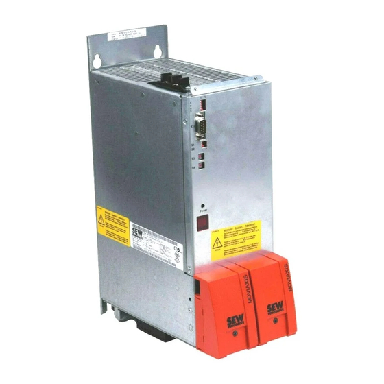
- Page 1 Drive Technology \ Drive Automation \ System Integration \ Services System Manual ® MOVIAXIS Multi-Axis Servo Inverter Edition 09/2013 20062540 / EN...
- Page 2 SEW-EURODRIVE—Driving the world...
-
Page 3: Table Of Contents
Contents Contents System description ..................... 7 ® Overview of MOVIAXIS system components..........7 Additional system and automation components ........10 ® Benefits and key features of MOVIAXIS ..........11 ® Areas of application and automation options with MOVIAXIS ....30 Option cards providing more functions and flexibility for axis modules and supply and regenerative modules ........ - Page 4 Contents Additional system components ..............225 Suitable encoder systems............... 225 Gear units from SEW-EURODRIVE ............228 ® ® MOVI-PLC , MOVI-PLC I/O ..............229 Appendix......................231 Additional documentation from SEW-EURODRIVE........ 231 ® Disposal of MOVIAXIS units ..............231 Parameter description ..................232 Parameter description for display values ..........
- Page 5 Contents 13.7 Unit structure of the MXR supply and regenerative module ....503 13.8 Unit structure of MXA axis modules ............504 ® 13.9 System bus in EtherCAT -compatible or CAN-based design....510 13.10 Unit design of the MXM master module component ....... 511 13.11 Unit design of the MXC capacitor module component ......
- Page 6 Contents Operation ......................675 16.1 General information ................675 16.2 Displays of the supply and axis modules ..........676 16.3 Operating displays and errors of the MXP power supply module ... 679 16.4 Operating displays and errors of MXA axis module ........ 680 16.5 MXC capacitor module operating displays..........
-
Page 7: System Description
System description ® Overview of MOVIAXIS system components System description ® Overview of MOVIAXIS system components Supply and regenerative units Supply unit: MXP power supply module Description: (page 13) Technical data: (page 106) Communication of regenerative modules ® EtherCAT fieldbus XFE24A Supply and regenerative unit: Description: (page 133) MXR80 and MXR81 supply... - Page 8 System description ® Overview of MOVIAXIS system components Inverter series Option cards for axis modules XGS11A, XGH11A multi-encoder card Description: (page 138) PROFIBUS fieldbus XFP11A Description: (page 132) ® EtherCAT fieldbus XFE24A MXA axis module Description: (page 133) Description: (page 21) EtherCAT EtherCAT ®...
- Page 9 System description ® Overview of MOVIAXIS system components Additional units MXS 24 V switched-mode MXC capacitor module power supply module Description: (page 28) Description: (page 27) Technical data: (page 125) Technical data: (page 127) MXZ DC link discharge mod- MXB buffer module Description: (page 28) Description: (page 29) Technical data: (page 126)
-
Page 10: Additional System And Automation Components
CMDV55 – 162 Compact, highly dynamic servomotor, form-closed mounting to all SEW gear The new compact servomotor series units. from SEW-EURODRIVE. The CMPZ has an increased intrinsic inertia for high external loads. Description: (page 219) Description: (page 217) DRL71 – 225... -
Page 11: Benefits And Key Features Of Moviaxis
Highly dynamic drive solution Technology and motion control functions that meet the highest standards, combined with maximum dynamics, integrated energy saving technology, and global availability – All this is provided by SEW-EURODRIVE’s modular system of highly dynamic servo ® drives. MOVIAXIS is the perfect multi-axis servo inverter for drive and automation so- lutions that save time, costs and effort. - Page 12 System description ® Benefits and key features of MOVIAXIS 1.3.6 Description ® MOVIAXIS multi-axis servo inverters have been designed for compact machine and plant automation systems at the highest stage. Productivity and intelligence are combined in an ideal way, allowing for a wide range of applications. ®...
- Page 13 System description ® Benefits and key features of MOVIAXIS 1.3.8 MXP power supply modules The power supply module provides energy to up to 8 axis modules as standard. It con- trols the regenerated energy via a braking resistor or via DC link storage to separate capacitor or buffer modules.
- Page 14 System description ® Benefits and key features of MOVIAXIS Scope of delivery • Touch guards • DC link connections • Electronics shield clamp • Power shield clamp • 24 V supply cable ® • Connection cable for CAN-based system bus/EtherCAT -compatible system bus •...
- Page 15 System description ® Benefits and key features of MOVIAXIS 1.3.9 MXP81 compact power supply module 10 kW The compact power supply module provides energy to up to 8 axis modules as stan- dard. It controls the regenerated energy via an integrated braking resistor or via an ex- ternal braking resistor and DC link storage to an integrated energy buffer.
- Page 16 System description ® Benefits and key features of MOVIAXIS Scope of delivery • Touch guards • DC link connections • Electronics shield clamp • Power shield clamp • 24 V supply cable ® • Connection cable for CAN-based system bus/EtherCAT -compatible system bus •...
- Page 17 System description ® Benefits and key features of MOVIAXIS 1.3.10 MXR80 supply and regenerative modules (sinusoidal) Supply and regenerative modules provide energy to up to 8 axis modules as standard. They feed back energy to the power grid via sinusoidal regeneration. A brake chopper is integrated as standard, e.g.
- Page 18 System description ® Benefits and key features of MOVIAXIS Unit data Supply voltage 3 x 380 V - 3 x 480 V ±10% Line frequency 50 - 60 Hz ± 5% Nominal DC link DC 750 V controlled voltage Overload capacity 200% for max.
- Page 19 System description ® Benefits and key features of MOVIAXIS 1.3.11 MXR81 supply and regenerative modules (block-shaped) Supply and regenerative modules provide energy to up to 8 axis modules as standard. They feed back energy to the power grid via block-shaped regeneration. A brake chop- per is integrated as standard, e.g.
- Page 20 System description ® Benefits and key features of MOVIAXIS Unit data Supply voltage 3 x 380 V - 3 x 480 V ±10% Line frequency 50 - 60 Hz ± 5% Nominal DC link DC 560 V , non-controlled voltage Overload capacity 225% for max.
- Page 21 System description ® Benefits and key features of MOVIAXIS 1.3.12 MXA axis modules The axis modules either communicate directly with a control over the integrated system buses or are controlled centrally via a master module. The modules can be optionally equipped with up to two safety relays for implementing "safe stop"...
- Page 22 System description ® Benefits and key features of MOVIAXIS Standard functionality of the axis modules Fieldbus/network communication MotionControl ® PROFIBUS × MOVI-PLC advanced × DeviceNet × IEC 61131 motion libraries × PROFINET × EtherNet/IP × CAN2 • Basic unit functions ®...
- Page 23 System description ® Benefits and key features of MOVIAXIS Unit data Nominal DC link volt- DC 560 V DC 750 V Output voltage 0 - max. V line Overload capacity 250% for max. 1 s Nominal output Nominal output Maximum output current at 8 kHz current at 4 kHz current...
- Page 24 System description ® Benefits and key features of MOVIAXIS Bus interface/sys- tem bus variants EtherCAT 2855065611 ® plus CAN-based system bus, SBus EtherCAT -compatible system bus SBus CAN-based application bus CAN2 (standard) Scope of delivery • DC link connections • Electronics shield clamp •...
- Page 25 System description ® Benefits and key features of MOVIAXIS 1.3.13 MXM master modules ® The master module extends the MOVIAXIS multi-axis servo system by various control, communication and data management functions. ® The master module is available as variant with MOVI-PLC advanced (32-bit motion controller) and fieldbus gateway.
- Page 26 System description ® Benefits and key features of MOVIAXIS Scope of delivery • Electronics shield clamp • 24 V supply cable • CAN master module connection cable • Cable lugs Optional • System bus connection cable for CAN-based system bus accessories ®...
- Page 27 The MXS switched-mode power supply unit can be combined with all MOVIAXIS mod- ules, except for the MXR supply and regenerative module. If you plan to combine MXS and MXR, please contact SEW-EURODRIVE. Unit data Nominal DC link voltage DC 560 V Nominal input backup voltage DC 24 V ±...
- Page 28 System description ® Benefits and key features of MOVIAXIS 1.3.15 MXC capacitor modules Capacitor modules are intelligent energy buffers. In the capacitor module, the energy supplied to the DC link when applying the brake of a motor is activated through a charging circuit and quickly "stored". During an acceler- ation process, this energy is then supplied back to the main DC link and utilized again.
- Page 29 The DC link discharge module is intended for discharge of kinetically stored energy only. Do not use the DC link discharge module for potential energy (hoist, spring, accumulator). INFORMATION For configuring a DC link discharge module, contact SEW-EURODRIVE. Unit data Nominal DC link voltage DC 560 V Convertible...
-
Page 30: Areas Of Application And Automation Options With Moviaxis
System description ® Areas of application and automation options with MOVIAXIS ® Areas of application and automation options with MOVIAXIS ® The MOVIAXIS multi-axis servo inverter was developed with the specific requirement to create additional value for the user, however different the applications may be. 1.4.1 High degree of flexibility and great user benefits ®... - Page 31 System description ® Areas of application and automation options with MOVIAXIS controls all processes. In general, only the positioning and travel commands or very time-critical tasks are handed down to the connected drive systems. Motion and Logic Control 2855985419 ® Application This variant of the MOVIAXIS master module is suitable for the following machines and...
- Page 32 System description ® Areas of application and automation options with MOVIAXIS Customer benefits The following features in particular offer sustainable customer benefits: • Motion control functions integrated in the axes, • Centralized communication, • Automatic data storage. Motion control integrated in the axis controller: functional, simple, and realized in the PLC program with very little effort.
- Page 33 Saving the settings SEW-EURODRIVE ensures that these important axis module settings are saved by means of a central data memory in the gateway. The data of all parameterizable axis modules is stored in the "data safe". If needed, it can be used for re-parameterization or recovery.
- Page 34 System description ® Areas of application and automation options with MOVIAXIS 1.4.3 Master module with integrated controller Higher-level machine and system PLC with lower-level module and segment controllers or control devices. Here, the higher-level PLC monitors and controls only the overall process, while lower- level module controllers, with a defined interface to the higher-level PLC, control the in- dividual modules and segments of a machine independently.
- Page 35 System description ® Areas of application and automation options with MOVIAXIS ® One platform for all – MOVI-PLC high-end motion control, PLC, kinematic and continuous path control The higher-level machine controller can be designed in such a way that it only performs additional "coordination and management tasks"...
- Page 36 • Ready-to-use and tested IEC-61131 libraries: Easy and fast programming of all drives from SEW-EURODRIVE. Use of configurable control units (CCU): Application modules for multi-axis applications that offer fast implementation without program- ming and protection against manipulation by the operator, •...
-
Page 37: Option Cards Providing More Functions And Flexibility For Axis Modules And Supply And Regenerative Modules
System description Option cards providing more functions and flexibility for axis modules and Option cards providing more functions and flexibility for axis modules and supply and regenerative modules ® MOVIAXIS offers a number of different option cards to expand the functionality of the individual axis modules or sinusoidal supply and regenerative modules and/or to make them more flexible. - Page 38 System description Option cards providing more functions and flexibility for axis modules and 1.5.1 Multi-encoder card option XGH11A, XGS11A ® The multi-encoder card expands the MOVIAXIS system for evaluation of additional en- coders. Two different multi-encoder cards are available. Their selection is based on the encoder type that is to be evaluated, see encoder list on the next page.
- Page 39 System description Option cards providing more functions and flexibility for axis modules and Multi-encoder card connection technology Suitable encoders The encoders that can be evaluated by the multi-encoder card are listed in the appendix of this publication (page 726). 1.5.2 Fieldbus interface option PROFIBUS XFP11A Terminal assignment switches...
- Page 40 System description Option cards providing more functions and flexibility for axis modules and ® 1.5.3 EtherCAT XFE24A fieldbus interface option ® The XFE24A fieldbus interface is a slave module for connection to EtherCAT networks. Only one XFE24A fieldbus interface can be installed per axis module. The XFE24A field- ®...
- Page 41 System description Option cards providing more functions and flexibility for axis modules and ® 1.5.4 EtherCAT -compatible XSE24A system bus option ® The EtherCAT -compatible system bus XSE24A is an optional, axis-internal expansion ® module. This module implements the functionality of an EtherCAT -compatible high- ®...
- Page 42 System description Option cards providing more functions and flexibility for axis modules and 1.5.5 Optional input/output card type XIO11A Terminal assignment Designation Terminal Plug Plug size DCOM +24 V DO 0 DO 1 DO 2 DO 3 DO 4 DO 5 DO 6 COMBICON 5.08 DO 7...
- Page 43 System description Option cards providing more functions and flexibility for axis modules and 1.5.6 Optional input/output card type XIA11A Terminal assignment Designation Terminal DCOM 24 V DO 0 DO 1 DO 2 DO 3 DI 0 DI 1 DI 2 COMBICON 5.08 DI 3 One core per terminal: 0.20 - 1.5 mm...
-
Page 44: Installation Variants, Combination And Communication Options
System description Installation variants, combination and communication options Installation variants, combination and communication options ® MOVIAXIS offers a high degree of flexibility for installation and combinations of the in- dividual system components. The mechanical installation options and the resulting com- munication options are described below. - Page 45 Number of In general, you can add up to 8 axis modules to a power supply module. After consulta- modules in the axis tion with SEW-EURODRIVE, it is possible to add more. system Two-row With a special DC link connection, you can install the axis system in two rows, which is configuration advantageous for narrow control cabinets (e.g.
- Page 46 An example for two-row configuration is the installation in the narrow aisles of a high- bay warehouse. If your application requires two-row configuration of your axis system, please contact SEW-EURODRIVE. ® The following figure shows an example of a two-row configuration of MOVIAXIS mod- ules.
- Page 47 System description Installation variants, combination and communication options ® The following MOVIAXIS modules can be combined: • [1] One MXM master module, • [2] One MXR regenerative power module or one MXP power supply module, • [3] A maximum of 4 MXA axis modules of size 1 or size 2, •...
- Page 48 System description Installation variants, combination and communication options 1.6.3 Connection of a safety-related BST brake module A connection kit is available for connecting a safety-related BST brake module to ® MOVIAXIS . This connection kit lets you continue the DC link via terminals to supply up to 8 BST brake modules with power.
- Page 49 System description Installation variants, combination and communication options The connection kit includes: • One insulator [1] • Three conductor rails [5] • One protection cap [2] • Various screws. The cable lugs [6] are not included in the scope of delivery. 1.6.4 Combination and communication options with and without master module ®...
- Page 50 System description Installation variants, combination and communication options Variants without The following table shows the individual connection variants with the main criteria for ap- master module plication adaptation. Communication cables are listed in chapter "System bus and con- nection cables – optional accessories" (page 66). Without With axis-inte- Fields of application...
- Page 51 System description Installation variants, combination and communication options ® ® With master module – MOVIAXIS connection – fieldbus network gateway or MOVI-PLC motion control ® The most powerful and cost-effective way to integrate MOVIAXIS in control and auto- mation structures is using the master module and the gateways. The master module it- self offers different variants and communication options.
- Page 52 System description Installation variants, combination and communication options Gate- MOVI- Parameter- Control system Standard cabling Optional/additional ® ization system bus cables access Control via DeviceNet or PROFI- - All SBus (CAN1) cables BUS controller of the axes are included in the scope of delivery - Adapter cable CAN2, Control via EtherNet/IP or Mod- ®...
- Page 53 MOVILINK 3.0 (or higher) from SEW-EURODRIVE is used for communica- tion via system bus. Option cards are available for real-time data transfer. The CAN-based system bus is not optional and must always be used because of the data exchange via the signaling bus.
- Page 54 System description Installation variants, combination and communication options System bus connection cable to other SEW units (optional) 2937250699 System bus connection cable CAN H orange Output plug black Terminating resistor CAN L orange-white Contact shield connection Cabling Length Designation Connection Grommet color Part number Axis system to other SEW...
- Page 55 System description Installation variants, combination and communication options 2. CAN-based application bus CAN2 (optional) 2937253899 CAN2 bus Adapter cable master module to CAN2 CAN2 for The CAN2 bus, which is available as standard on the front of the axis module, can be additional tasks used to implement various additional functions.
- Page 56 System description Installation variants, combination and communication options Cabling Length Designation Connection Grommet color Part number Connection cable for CAN-based applica- 3 × 210 1810 1585 tion bus CAN2 – 3 modules MXA to MXA Connection cable for CAN-based applica- 4 ×...
- Page 57 System description Installation variants, combination and communication options ® plus 3. EtherCAT -compatible system bus SBus ® plus The EtherCAT -compatible system bus SBus (XSE24A) is an optional, axis-internal ® expansion module. This module implements the functionality of an EtherCAT -compat- ®...
- Page 58 System description Installation variants, combination and communication options Length Designation Connection Grommet color Part number 1810 0287 Connection cable MXA to MXP Yellow/green 3000 0819 4971 ® Connection cable for EtherCAT master MXM to MXP Yellow/black 1810 0279 module System Manual – MOVIAXIS® Multi-Axis Servo Inverter...
- Page 59 System description Installation variants, combination and communication options System bus connection cable to other SEW units 2937482891 System bus connection cable Input plug green, RJ45 ® Output plug yellow SEW stations with SEW EtherCAT interface Cabling Length Designation Connection Grommet color Part number 1810 0287 Connection cable...
- Page 60 System description Installation variants, combination and communication options ® Communication with MOVI-PLC Power ® XSE EtherCAT option in all axis or supply and regenerative modules The XSE24A is part of the unit variant MXA8.A-...-503-0E, see chapter "MXA axis mod- ules / unit data" (page 23). 6739083915 ®...
- Page 61 System description Installation variants, combination and communication options ® OSCMB EtherCAT -CAN gateway in the master module 7403166987 ® [3] Cable for CAN-based and EtherCAT -compatible SBus ® EtherCAT connection cable system bus CAN connection cable f. master module Cabling Length Designation Connection...
- Page 62 System description Installation variants, combination and communication options ® ® ® ® 1.6.5 Combinations of MOVIAXIS axis systems with MOVIAXIS , MOVIDRIVE , MOVITRAC ® In addition to the combination options and flexibility within the axis system, MOVIAXIS with the master module as the central element allows for further connection and instal- lation options: 1.
-
Page 63: Installation And Connection Accessories
System description Installation and connection accessories Installation and connection accessories 1.7.1 Standard accessories Standard accessories are included with the basic unit at delivery. 9007202205751307 System Manual – MOVIAXIS® Multi-Axis Servo Inverter... - Page 64 System description Installation and connection accessories The mating connectors for all connections are installed at the factory. An exception are D-sub connectors, which are supplied without mating connector. Assignment table for standard accessories – Mechanical accessories Accessory 1821 1821 1820 2616 1820 2632 pack 7583...
- Page 65 System description Installation and connection accessories Assignment table for standard accessories – Electric accessories Accessory 1821 1820 1821 1820 2624 1820 2640 pack 7591 3329 3006 MXP in kW MXA in A Dimen- sion 24 V supply cable [12] 40 mm [13] 50 mm [14] 80 mm [15] 110 mm...
- Page 66 System description Installation and connection accessories 1.7.4 System bus and connection cables – optional accessories (overview) [10] [11] 9007202205688459 System Manual – MOVIAXIS® Multi-Axis Servo Inverter...
- Page 67 System description Installation and connection accessories Assignment table for optional accessories Dimensions / designation / connector type Part number System bus connection cable CAN (axis system to axis system) [1] 750 mm 2 × RJ45 (special assignment) 0819 7261 [2] 3000 mm 2 × RJ45 (special assignment) 0819 8993 System bus connection cable for CAN-based system bus SBus (axis system with other SEW units) 750 mm RJ45 / open end...
-
Page 68: Technology And Unit Functions
System description Technology and unit functions Technology and unit functions 1.8.1 Control modes, machine control, and auto-tuning CFC control mode (current-mode flux control) ® Characteristics MOVIAXIS uses a high-performance, current-controlled control mode for synchronous and asynchronous servomotors. This control mode was optimized and further devel- oped particularly for highly dynamic servo applications. - Page 69 System description Technology and unit functions Motor inductance compensation In modern, tooth-wound servomotors with high utilization (e.g. CMP motors), the induc- tance is changed via the impressed motor current. In case of high overload, this can lead to suboptimal motor control unless this behavior is compensated by the inverter. ®...
- Page 70 System description Technology and unit functions Automated startup and controller optimization Auto-tuning / easy tuning 2951355531 Two easily adjustable sliders are used to set an optimum controller setting for each axis. Using two advanced algorithms, the two controllers influence various parameters of the control loops.
- Page 71 System description Technology and unit functions Expert tuning 2951358731 Based on the schematic representation, the control loops can also be set manually for very sophisticated drive tasks. Graphical setting aids and interactive menus that are selected directly in the illustration plus setting diagrams that visualize the made settings allow experts to access and mod- ify all relevant controller data.
- Page 72 System description Technology and unit functions Dual drive The "dual drive" function is a special form of synchronous operation. Its objective is to distribute the load under special basic conditions, e.g. position synchronicity, crash safety. Seen from the outside, the drives operated in a system are given a speed setpoint. Within the axis system, the drives are all synchronous in terms of position.
- Page 73 System description Technology and unit functions Jerk-limited profile generator ® MOVIAXIS has a jerk-limited profile generator. This jerk-limitation feature is required in particular with highly-dynamic positioning processes to position the axes with the relevant dynamic properties and to protect the mechanical machine components. ®...
- Page 74 System description Technology and unit functions Software and hardware limit switches A certain travel range of a drive can be monitored using hardware limit switches. If hardware limit switches are not installed, or if, for example, an early warning alarm is to be activated when a specific position is exceeded, the software limit switches ®...
- Page 75 System description Technology and unit functions Basic control modes ® MOVIAXIS usually operates with the CFC control mode for asynchronous and ® synchronous motors with encoder feedback. MOVIAXIS can be operated in the basic control modes torque, speed and position control. This means that the customer can activate closed-loop control circuits where they are most suitable for the application.
- Page 76 System description Technology and unit functions Interpolated speed control For applications with a higher-level (motion control) controller, this controller usually cal- culates a track profile (x, y, z) for several drive axes. The axis is then assigned one set- point (position, speed, torque) that it has to follow. ®...
- Page 77 System description Technology and unit functions Modulo in positive The position setpoint in user-defined units is interpreted as the offset for the last setpoint direction with that was transferred. After it has been converted into system units, it is added to the last relative position setpoint.
- Page 78 System description Technology and unit functions ® Jog mode MOVIAXIS has a position-controlled jog mode function; this means it is possible to move an axis in positive or negative direction, for example, for alignment purposes in position control mode using two adjustable speeds for each direction. The advantage of this function is that it can be used with hoist applications for which the position is not permitted to change when a change in load occurs when the drive is at a standstill.
- Page 79 System description Technology and unit functions Application and system limit values The entry of application and system limits in user-defined units allows the user to set lim- its for acceleration and velocities separately. They are set once according to the maxi- mum load of the mechanics of machinery (machine limit value) and according to the product (application limit value).
- Page 80 The 24 V holding brake can be used for CMP motors. In every application, a holding brake can be controlled via a customer relay with varistor overvoltage protection or via the BMV brake control unit from SEW-EURODRIVE. Direct brake con-...
- Page 81 Expressly excluded are brakes of the motor types CMP80 and greater, CMPZ mo- tors, and all non-SEW brakes. • Only prefabricated brakemotor cables from SEW-EURODRIVE must be used. • The brakemotor cable must be shorter than 25 m. Digital inputs and outputs ®...
- Page 82 System description Technology and unit functions 1.8.4 Communication profiles ® Depending on the used system buses "CAN-based" or "EtherCAT -compatible", the fol- lowing communication profiles are possible: ® Profile CAN-based sys- EtherCAT -compatible CAN-based application plus tem bus, SBus system bus SBus bus CAN2 ®...
- Page 83 System description Technology and unit functions ® The following comparison gives an overview of the MOVIAXIS energy saving modules with their main application data and customer benefits: Product pur- Energy stor- Braking resis- Product Power Application Customer benefits pose • No complex •...
- Page 84 System description Technology and unit functions 1.8.6 Diagnostics and scope function Diagnostics ® Energy meter The MXR supply and regenerative module of the MOVIAXIS series can analyze the energy flow between the axis system and the supply system, and uses an energy feed- back meter to determine the amount of energy that has been saved.
- Page 85 System description Technology and unit functions 1.8.7 Monitoring, protection, and test functions Process safety and plannable productivity can only be ensured if the drive is running reliably and "thinking ahead". The consequences of an unintended system standstill can ® be dramatic. To prevent this, MOVIAXIS offers a number of monitoring and check func- tions.
- Page 86 System description Technology and unit functions Brake test This function is used to check the braking capability of a brake connected to ® MOVIAXIS . A test torque is applied electrically via the motor when the brake is applied. Even when the brake has passed the brake test, it does not take on any safety functions ®...
- Page 87 This function is recommended for directly coupled loads that cannot be disengaged via an adapter, or not without difficulty. If you want to make use of this function, please contact SEW-EURODRIVE. Controlled stop in case of power failure In case of a power failure, the standard application of a working brake can cause exces- sive strain in critical applications or sensitive mechanical systems.
-
Page 88: Functional Safety / Safety Functions
System description Functional safety / safety functions Functional safety / safety functions You find more detailed information on this topic in the publication "Functional Safety" for ® MOVIAXIS 1.9.1 Functions integrated in the unit ® Safety technology can be integrated in the basic unit of the MOVIAXIS multi-axis servo inverter. - Page 89 System description Functional safety / safety functions Safety functions The following, drive-related safety functions can be realized with the axis-integrated safety functions: • Safe torque off (STO) Safe Torque Off according to IEC 61800-5-2 via disconnection of the safety-related 24 V supply If the STO function is activated, the frequency inverter no longer supplies power to the motor for generating torque.
- Page 90 System description Functional safety / safety functions • Safe stop 1 (SS1(c)) Safe Stop 1, function variant c according to IEC 61800-5-2 via suitable external con- trol (e.g. safety relay with delayed disconnection) The following procedure must be observed for this safety function: –...
- Page 91 System description Functional safety / safety functions Units with one safety relay The following axis modules meet performance level d according to EN ISO 13849-1 in observance of the safety guidelines (conditions): Type designation Nominal current in Size MXA81A-0.2-503-0. MXA81A-0.4-503-0. MXA81A-0.8-503-0.
-
Page 92: Movitools ® Motionstudio Engineering Software
® The new MOVITOOLS MotionStudio is a consistent modular software system for all drive electronics products from SEW-EURODRIVE. The advantage for the system man- ufacturer and operator is that only one software package is required for comprehensive engineering. System Manual – MOVIAXIS® Multi-Axis Servo Inverter... - Page 93 System description ® MOVITOOLS MotionStudio engineering software Designation Screenshot Description Configuration and startup: To adapt the inverter to the connected Startup motor and to optimize the current, speed and position controllers. A process data object editor for graphic configuration of the PDO Editor ®...
- Page 94 System description ® MOVITOOLS MotionStudio engineering software 1.10.1 Overview of features • Application programs to IEC 61131-3 can be used for all products based on the PLC Editor • Different communication media and fieldbus systems can be used. • Handling of projects with several different units (multi-unit perspective). •...
-
Page 95: Sew Workbench" Project Planning Software
System description "SEW WORKBENCH" project planning software PDO Editor The PDO Editor is the central, graphical software tool for editing and configuring FCBs Process Data and the entire unit functionality. Object Editor The tool can be used to determine where and which data packages should be retrieved from buses or I/O, how they should be interpreted (control/process data), how they are used in the unit functions, and how this data is then output again (via bus or I/O). - Page 96 System description "SEW WORKBENCH" project planning software The user has the option to access existing functions and programs such as EKAT, SAP Configurator and ProDrive as well as to use new functions. Servo project ProDrive DocuFinder DriveCAD planning Electronic Determining catalog oil amounts Office...
- Page 97 System description "SEW WORKBENCH" project planning software 2954405131 1.11.1 SEW Workbench functions Different catalog functions and project planning functions are available for selecting in- dividual components. Each component is represented in the work area by a graphical object. The result of the total of the objects together is the drive system. A complete check is performed for all products after the user has created the complete drive system.
-
Page 98: Technical Data
• Compliance with limit class "C2" according to EN 61800-3 has been tested on a specified test setup. SEW-EURODRIVE can provide detailed information on request. The CE mark on the nameplate indicates conformity with the Low Voltage Directive 2006/95/EC and the EMC Directive 2004/108/EC. We can provide a declaration of conformity on request. - Page 99 Technical data CE marking and UL approval 2.1.3 UL approval of the line components NF.. line filter for MXP power supply module ® Independent of the MOVIAXIS multi-axis servo inverter, the listed NF... line filters have a component approval. • NF018-503 •...
-
Page 100: Type Designation
Technical data Type designation Type designation ® 2.2.1 Type designation for MOVIAXIS basic units The following diagram shows the type designation: -004 - 00 00 = Standard version 01-99 = Special design ® plus 0E = Axis module with built-in, EtherCAT -compatible SBus system bus 3-phase connection type... - Page 101 Technical data Type designation Type designation for the axis module: MXA80A-004-503-00 Axis module with 4 A nominal current plus Axis module with 4 A nominal current and integrated SBus MXA80A-004-503-0E system bus Type designation for the buffer module component MXB80A-050-503-00 Buffer module with a capacity of 5000 µF Type designation for the capacitor module component...
- Page 102 Technical data Type designation ® 2.2.2 MOVIAXIS MX communication module option Version Version status 11 = PROFIBUS ® 24 = EtherCAT Execution: FP = PROFIBUS DP V1 IO = Digital input/output component IA = Analog input/output component FA = K-Net GH, GS= Multi-encoder card ®...
-
Page 103: General Technical Data
Technical data General technical data General technical data ® The following tables lists the technical data for all MOVIAXIS MX multi-axis servo in- verters independent of • Type • Variant • Size • Power rating ® MOVIAXIS Interference immunity Meets EN 61800-3 Interference emission with EMC-compliant Category "C2"... -
Page 104: Rear View Of Housing And Bore Patterns
Technical data Rear view of housing and bore patterns 2.3.1 Suitability of standard digital inputs INFORMATION It is not permitted to control the standard digital inputs with safety-related (pulsed) volt- ages (except X7 and X8 at MXA). 2.3.2 24 V supply For projecting the 24 V supply, see system manual, chapter "Project planning"... - Page 105 Technical data Rear view of housing and bore patterns 2955493387 Position of tapped hole See table with dimensions (page 104) System Manual – MOVIAXIS® Multi-Axis Servo Inverter...
-
Page 106: Technical Data Of The Modules
Technical data Technical data of the modules Technical data of the modules 2.5.1 Technical data of MXP power supply modules Power section of power supply module sizes 1 – 3 ® Size MOVIAXIS power supply module MXP80A-...-503-00 Type INPUT Supply voltage AC V 3 ×... - Page 107 Technical data Technical data of the modules ® Size MOVIAXIS power supply module MXP80A-...-503-00 GENERAL INFORMATION Power loss at nominal capacity No. of times power may be switched < 1/min on/off Minimum switch-off time for power > 10 Mass 10.3 10.8 Dimensions: 1) Nameplate information...
- Page 108 Technical data Technical data of the modules Power section of MXP81 compact power supply module The technical data of the MXP81 power supply module with integrated braking resistor correspond to those of the power supply module size 1. Deviating data is listed below: ®...
- Page 109 Technical data Technical data of the modules Dimension sheet of MXP8.A-10.. 210,5 MXP8.A-10... 9243395595 System Manual – MOVIAXIS® Multi-Axis Servo Inverter...
- Page 110 Technical data Technical data of the modules Dimension sheet of MXP80A-025.. 210,5 MXP80A-025... 9243397515 System Manual – MOVIAXIS® Multi-Axis Servo Inverter...
- Page 111 Technical data Technical data of the modules Dimension sheet of MXP80A-050, 075.. 210,5 MXP80A-50,75... MXR80A-50,75... 9243399435 System Manual – MOVIAXIS® Multi-Axis Servo Inverter...
- Page 112 Technical data Technical data of the modules 2.5.2 Technical data of MXR supply and regenerative modules Sinusoidal regeneration with MXR80A ® MOVIAXIS MXR80 Informa- tion on MXR supply and regenerative module Unit name- plate INPUT Supply voltage AC V 3 × 400 V – 3 × 480 V ±10% line Nominal line voltage 75 kW...
- Page 113 Technical data Technical data of the modules Block-shaped regeneration with MXR81A Informa- Supply and regenerative module tion on ® MOVIAXIS MXR81 Unit Supply and regenerative module 50 kW 75 kW name- plate INPUT Supply voltage AC V 3 × 380 V – 3 × 480 V ±10% line Nominal line voltage Nominal line current...
- Page 114 Technical data Technical data of the modules Control section of MXR80/MXR81 supply and regenerative module ® MOVIAXIS General electronics data MXR supply and regenerative module INPUT DC 24 V voltage supply DC 24 V ± 25% (EN 61131) COMBICON 5.08 Cross section and contacts One core per terminal: Max.
- Page 115 Technical data Technical data of the modules Dimension sheet of MXR8.A-050, 075.. 210,5 MXP80A-50,75... MXR80A-50,75... 9243399435 System Manual – MOVIAXIS® Multi-Axis Servo Inverter...
- Page 116 Technical data Technical data of the modules 2.5.3 Technical data of MXA axis modules Axis module power section ® Size MOVIAXIS axis module MXA8.A-...-503-0. Type INPUT (DC link) Nominal DC link voltage V DC 560 NDCL Nominal DC link current I NDCL Cross section and contacts...
- Page 117 Technical data Technical data of the modules ® Size MOVIAXIS axis module MXA8.A-...-503-0. GENERAL INFORMATION Power loss at nominal capacity 1100 Mass 15.6 15.6 Dimensions: 1) Nameplate information 2) Unit 3) With simplification: I (typical motor application) NDCL 4) Material thickness [mm] × width [mm] 5) For V = 3 ×...
- Page 118 Technical data Technical data of the modules Control section axis module ® MOVIAXIS MX axis module General electronics data DC 24 V voltage supply DC 24 V ± 25% (EN 61131) COMBICON 5.08 Cross section and contacts One core per terminal: 0.20 - 1.5 mm Two cores per terminal: 0.25 - 1.5 mm...
- Page 119 Technical data Technical data of the modules Dimension sheet of MXA80A-002, 008, 012, 016.. 210,5 MXA8.A-002, 008, 012, 016... 9243401355 System Manual – MOVIAXIS® Multi-Axis Servo Inverter...
- Page 120 Technical data Technical data of the modules Dimension sheet of MXA80A-024.. 210,5 MXA80A-024... 9243403275 System Manual – MOVIAXIS® Multi-Axis Servo Inverter...
- Page 121 Technical data Technical data of the modules Dimension sheet of MXA80A-032.. 210,5 MXA80A-032... 9243430795 System Manual – MOVIAXIS® Multi-Axis Servo Inverter...
- Page 122 Technical data Technical data of the modules Dimension sheet of MXA80A-048, 064, 100.. 210,5 MXA80A-048,064,100... 9243432715 System Manual – MOVIAXIS® Multi-Axis Servo Inverter...
- Page 123 Technical data Technical data of the modules 2.5.4 Technical data for MXM master module component ® MOVIAXIS MX master module Size 1 MXM80A-...-000-00 Type Supply voltage V DC 24 V ± 25% according to EN 61131 COMBICON 5.08 Cross section and contacts (X5a) One core per terminal: 0.20 –...
- Page 124 Technical data Technical data of the modules Dimension sheet of MXM80A.. 210,5 2956148363 System Manual – MOVIAXIS® Multi-Axis Servo Inverter...
- Page 125 Technical data Technical data of the modules 2.5.5 Technical data of MXC capacitor module component ® MOVIAXIS capacitor module MXC80A-050-503-00 Type INPUT Nominal DC link voltage V DC 560 NDCL Storable energy 1000 Peak power capacity Cross section and contacts CU bars 3 ×...
- Page 126 Technical data Technical data of the modules 2.5.6 Technical data of MXB buffer module component ® MOVIAXIS buffer module MXB80A-050-503-00 Type INPUT Nominal DC link voltage DC 560 NDCL Cross section and contacts CU bars 3 × 14 mm, M6 screw fitting GENERAL INFORMATION Capacitance μF...
- Page 127 Technical data Technical data of the modules 2.5.7 Technical data of MXS 24 V switched-mode power supply module component ® MOVIAXIS 24 V switched-mode power supply module MXS80A-...-503-00 Type INPUT via DC link Nominal DC link voltage V DC 560 NDCL Cross section and contacts...
- Page 128 Technical data Technical data of the modules Dimension sheet of MXS80A.. 210,5 2956222731 System Manual – MOVIAXIS® Multi-Axis Servo Inverter...
- Page 129 Technical data Technical data of the modules 2.5.8 Technical data of MXZ DC link discharge module component Power section of DC link discharge module ® MOVIAXIS DC link discharge module Size 1 MXZ80A-...-503-00 Type INPUT (DC link) Nominal DC link voltage DC 560 NDCL Cross section...
- Page 130 Technical data Technical data of the modules Dimension sheet of MXZ80A.. 210,5 2957099275 2.5.9 Two-row configuration of the axis system – technical data The following table lists only the data that deviates from the technical data listed above due to two-row configuration. ®...
- Page 131 Technical data Technical data of the modules 2.5.10 Connection kit for BST brake module – technical data The following table lists only the data that deviates from the technical data listed above due to the installation of a BST brake module. ®...
-
Page 132: Technical Data Of Option Cards For Axis Modules And Regenerative Modules
Technical data Technical data of option cards for axis modules and regenerative modules Technical data of option cards for axis modules and regenerative modules 2.6.1 Technical data of XFP11A communication option Description The XFP11A communication module is a PROFIBUS slave module for direct integration ®... - Page 133 Technical data Technical data of option cards for axis modules and regenerative modules ® 2.6.2 Technical data of EtherCAT fieldbus interface option ® Description of The XFE24A fieldbus interface is a slave module for connection to EtherCAT networks. XFE24A Only one XFE24A fieldbus interface can be installed per axis module. The XFE24A field- ®...
- Page 134 Technical data Technical data of option cards for axis modules and regenerative modules 2.6.3 Technical data of K-Net communication option Description The XFA11A (K-Net) communication module is a slave module for connection to a serial bus system for high-speed data transfer. No more than one XFA11A (K-Net) communi- ®...
- Page 135 Technical data Technical data of option cards for axis modules and regenerative modules 2.6.4 Technical data of XIO11A, XIA11A input/output option Description The input/output modules XIO11A/XIA11A are digital or digital/analog hybrid option modules. They can be used to read or send both digital and analog signals from the servo inverter.
- Page 136 Technical data Technical data of option cards for axis modules and regenerative modules XIA11A ana- log/digital hybrid General module Supply voltage DC 24 V ± 25%, 2 A (EN 61131-1) Supply of IOs from the front Addressing via 16-digit address switch (positions 1 and 3 only) COMBICON 5.08 Connection contacts One core per terminal: 0.20 –...
- Page 137 Technical data Technical data of option cards for axis modules and regenerative modules Digital outputs Number of outputs Output type Digital outputs according to EN 61131-2 Nominal voltage DC 24 V Processing time 1 ms Nominal current 0.5 A Power loss 0.1 W with nominal current (R : 400 mΩ) on max...
- Page 138 Technical data Technical data of option cards for axis modules and regenerative modules 2.6.5 Technical data of XGS11A, XGH11A multi-encoder card option Description XGS, XGH multi-encoder card Unit Power consumption via integrated supply bus (without con- nected encoder) Output current for supplying connected encoders Peak output current I for 400 ms When using 2 encoder cards, the total current must be limited to 800 mA.
- Page 139 Technical data Technical data of option cards for axis modules and regenerative modules 2.6.6 Technical data of DWI11A Connection of TTL encoder to XGH, XGS multi-encoder cards TTL encoder The following encoders can be connected at X63, X64 (external encoder input): •...
- Page 140 Use prefabricated cables from SEW-EURODRIVE for the encoder connection (page 214). ® SEW-EURODRIVE offers a prefabricated cable for connecting DWI11A to MOVIAXIS This cable can be used for both asynchronous and synchronous motors. Dimension drawing All dimensions in mm (in) 68 (2.7)
-
Page 141: System Accessories
The short-time load capacity of the wire and grid resistors is greater than in the flat- type braking resistors. SEW-EURODRIVE recommends protecting the wire and grid resistors against overload using a thermal overload relay or a thermal circuit breaker. Set the trip current to the value I except when using the braking resistor type BW...-P, see the following tables. - Page 142 Technical data System accessories Technical data BW027- BW027- BW247 BW247-T BW347 BW347-T BW039- Braking resistor type Part number 822 4226 822 4234 820 7143 1820 0842 820 798 4 1820 1350 821 691 6 Power class of the power 10, 25, 50, 75 supply module Load capacity at 100% cdf...
- Page 143 Technical data System accessories BW012- BW012- BW12- BW012- BW012- Braking resistor type BW012-015 BW915-T 015-01 025-P 100-T Part number 821 679 7 1 820 010 9 821 680 0 1820 4147 821 681 9 1820 1415 1820 4139 Power class of the power 25, 50, 75 supply module Load capacity at...
- Page 144 Technical data System accessories Dimension drawing of BW... braking resistors Dimension drawing of BW braking resistors, [2] grid resistor / [3] wire resistor 2961094539 Flat-type resistors: The connecting lead is 500 mm long. The scope of delivery includes four M4 threaded bushings each of type 1 and 2. Type Mounting Main dimensions...
- Page 145 Technical data System accessories 2.7.2 Technical data of line filter option for power supply module • To suppress interference emission on the line side of inverters. ® • Do not switch between the NF... line filter and MOVIAXIS ® • NF..
- Page 146 Technical data System accessories Dimension drawing for line filters NF018-503 / NF048-503 / NF085-503 / NF150-503 LINE LOAD 1456387083 Any mounting position Mounting dimensions mm Hole dimension Main dimensions mm (in) Mass Line filter PE con- (in) mm (in) type nection kg (lb) NF018-503...
- Page 147 Technical data System accessories 2.7.3 Technical data of line choke option for power supply modules Using line chokes is optional: • To support overvoltage protection • To smoothen the line current, to reduce harmonics • Protection in the event of distorted line voltage •...
- Page 148 Technical data System accessories Dimension drawing for line choke ND020.. / ND045.. / ND085.. 1U1 1U2 1V1 1V2 1W1 1W2 1455926923 Space for installation terminals Input: 1U1, 1V1, 1W1 Any mounting position Output: 1U2, 1V2, 1W2 Hole dimension Main dimensions mm (in) Mounting dimensions mm (in) Mass Line choke...
- Page 149 Wiring diagram 2961542411 ® Technical data NDR.. line chokes have a component approval independent of the MOVIAXIS multi- axis servo inverter. SEW-EURODRIVE will provide certification on request. Unit Line choke NDR 075-083 (50 kW) NDR 110-063 (75 kW) Connection voltage AC 3 ×...
- Page 150 Technical data System accessories Unit Line choke NDR 075-083 (50 kW) NDR 110-063 (75 kW) Mass Dimensions Mounting dimen- sions 1) Max. operating voltage in conjunction with MXR 2) Max. operating voltage of the choke Dimension drawing NDR 075-083 (50 kW) 11x15 W2 V2 U2 W1 V1 U1...
- Page 151 Technical data System accessories Dimension drawing NDR 110-063 (75 kW) 11x15 W2 V2 U2 W1 V1 U1 2961686923 System Manual – MOVIAXIS® Multi-Axis Servo Inverter...
- Page 152 Touch-safe connection terminals ® Technical data NFR.. line filters have a component approval independent of the MOVIAXIS multi-axis servo inverter. SEW-EURODRIVE will provide certification on request. Line filter Unit NFR 075-503 (50 kW) NFR 111-503 (75 kW) Connection voltage AC 3 ×...
- Page 153 Technical data System accessories Dimension drawing for NFR 075-503 (50 kW) Dimension drawing of line filter for 3-phase systems. L1 L2 L3 221.5 L1' L2' L3' 9007202216569099 Terminals for line phase measure- ment System Manual – MOVIAXIS® Multi-Axis Servo Inverter...
- Page 154 Technical data System accessories Dimension drawing for NFR 111-503 (75 kW) Dimension drawing of line filter for 3-phase systems. L1 L2 L3 221.5 L1' L2' L3' 9007202216572299 Terminals for line phase measure- ment System Manual – MOVIAXIS® Multi-Axis Servo Inverter...
- Page 155 Technical data System accessories 2.7.5 Technical data of the EcoLine filter for MXR80 supply and regenerative modules Every regenerative unit, be it block-shaped or sinusoidal, affects the grid to which it is connected. To limit these feedback effects on other consumers connected to the grid, and to keep them within a safe range under all circumstances, the transformer must be overdimensioned or the grid must be sufficiently strong.
- Page 156 Technical data System accessories Dimension drawing of NFH EcoLine filter L1' L2' L3' L1 L2 L3 9007202216688139 EcoLine filter Unit NFH 075-503 (50 kW) NFH 110-503 (75 kW) Dimensions Mounting dimen- sions Mounting positions The preferred mounting positions are suspended and horizontal, see the following sche- matic diagrams: Suspended 2962077323...
- Page 157 Technical data System accessories Horizontal 2962080139 INFORMATION For installation, observe the required minimum clearance of 100 mm above and below the connecting terminals and the ventilation openings. System Manual – MOVIAXIS® Multi-Axis Servo Inverter...
- Page 158 ND.. line choke Wiring diagram ® Technical data ND.. line filters have a component approval independent of the MOVIAXIS multi-axis servo inverter. SEW-EURODRIVE provides proof for this on request. Unit Line choke ND085-0053 (50 kW) ND150-0033 (75 kW) 1797 0679...
- Page 159 Technical data System accessories Dimension drawing System Manual – MOVIAXIS® Multi-Axis Servo Inverter...
- Page 160 NF.. line filters for 3-phase systems ® Technical data NF.. line filters have a component approval independent of the MOVIAXIS multi-axis servo inverter. SEW-EURODRIVE provides proof for this on request. Line filter Unit NF115-503 (50 kW) NF150-503 (75 kW) Part number...
- Page 161 Technical data System accessories Dimension drawing LINE LOAD System Manual – MOVIAXIS® Multi-Axis Servo Inverter...
- Page 162 (page 80). Cable cross sections and fusing SEW-EURODRIVE proposes the following line cross-sections and fusing for single-core copper cables with PVC insulation laid in cable ducts, an ambient temperature of 40 °C and nominal system currents of 100% of the nominal unit current:...
- Page 163 Technical data System accessories ® MOVIAXIS MXP power supply modules: ® MOVIAXIS Size 1 MXP81 Size 2 Size 3 Nominal output power kW Line connection Nominal line current AC A Fuses F11/F12/F13 Dimensioning according to nominal line current Line cable L1/L2/L3 1.5 –...
- Page 164 Technical data System accessories Voltage drop The cable cross section of the motor cable should be selected so the voltage drop is as small as possible. An excessively large voltage drop means that the full motor torque is not achieved. The expected voltage drop can be determined with reference to the following tables (the voltage drop can be calculated in proportion to the length if the cables are shorter or lon- ger).
-
Page 165: Power Cables For Synchronous Servomotors
Power cables for synchronous servomotors Structure of the motor cable and brakemotor cables SEW-EURODRIVE offers prefabricated cables with plugs for straightforward and reli- able motor connection. Cable and contact are connected using the crimp technique. The following cables are available in 1 m steps: •... - Page 166 Line length ≤ 10 m: Tolerance +200 mm. Cable length > 10 m: Tolerance +2%. Permitted cable length according to the technical docu- ments SEW-EURODRIVE logo printed on Prefabricated cable end for inverter cable Required loose parts are supplied with the cable.
- Page 167 Structure of the motor cable and brakemotor cables 3.1.3 Motor cables/brakemotor cables for CFM servomotors 2962611339 Connector: Amphenol SEW-EURODRIVE logo printed on cable Nameplate Cable length ≤ 10 m: Tolerance +200 mm. Cable length > 10 m: Tolerance +2%. Permitted line length according to the technical documents.
-
Page 168: Power Cables For Cmp, Cmdv, And Cms50/63 Motors
Power cables for synchronous servomotors Power cables for CMP, CMDV, and CMS50/63 motors Power cables for CMP, CMDV, and CMS50/63 motors 3.2.1 Motor cable Motor cable illustration 2962797323 Pin assignment of the motor cable Plug connector Cable core color Assigned Extra View X BSTA 078... - Page 169 Power cables for synchronous servomotors Power cables for CMP, CMDV, and CMS50/63 motors Number of cores Plug connector type and cable cross Part number Installation Cable type section SMB10 4 × 10 mm 1335 0277 Fixed installation Cable carrier SMB10 4 ×...
- Page 170 Power cables for synchronous servomotors Power cables for CMP, CMDV, and CMS50/63 motors Pin assignment of motor extension cable Plug connector Cable core color Assigned Plug connector View X View Y (BK/WH) BKUA 199 BSTA 078 Black with white lettering BK/- U, V, W BK/+...
- Page 171 Power cables for synchronous servomotors Power cables for CMP, CMDV, and CMS50/63 motors Plug connector type Number of cores and Part number Installation Cable type cable cross section SBB6 4 × 6 mm + 3 × 1.5 mm 1335 0196 Fixed installation Cable carrier SBB6...
- Page 172 Power cables for synchronous servomotors Power cables for CMP, CMDV, and CMS50/63 motors 3.2.4 Brakemotor cable for BY brake Illustration of brakemotor cable 2963077131 Types of brakemotor cables Plug connector type Number of cores and Part number Installation Cable type cable cross section SB11 4 ×...
- Page 173 Power cables for synchronous servomotors Power cables for CMP, CMDV, and CMS50/63 motors Pin assignment of brake motor cable Plug connector Cable core color Assigned Extra View X BSTA 078 (BK/WH) Black with white lettering U, V, W BK/WH BK/WH (GN/YE) Green/Yellow n.
- Page 174 Power cables for synchronous servomotors Power cables for CMP, CMDV, and CMS50/63 motors 3.2.5 Extension cable for BP and BY brake Illustration of brakemotor extension cable 2962872843 Types of brake motor extension cables Plug connector type Number of cores and Part number Installation Cable type...
-
Page 175: Power Cables For Cfm And Cms71 Motors
Power cables for synchronous servomotors Power cables for CFM and CMS71 motors Power cables for CFM and CMS71 motors 3.3.1 Motor cable Motor cable illustration 2963366027 Motor cable types The cables are equipped with a connector for motor connection and conductor end sleeves for inverter connection. - Page 176 Power cables for synchronous servomotors Power cables for CFM and CMS71 motors Illustration of motor extension cable 2963397259 Types of motor extension cables The cables are equipped with a plug and adapter for extending the CFM motor cable. Plug connector type Number of cores and cable cross Routing Part number section...
- Page 177 Power cables for synchronous servomotors Power cables for CFM and CMS71 motors 3.3.2 Brakemotor cables Illustration of brakemotor cable 2963522699 Types of brakemotor cables Plug connector Number of cores and cable cross section Routing Part number type, complete SB 51 / SB 61 4 ×...
- Page 178 Power cables for synchronous servomotors Power cables for CFM and CMS71 motors CFM brakemotor cable – pin assignment The brakemotor cable is prefabricated for the following brake resistors: • • • • • For the BSG control unit, the customers have to assemble the cable themselves. Plug connector Core identification Assigned Contact type Extra...
- Page 179 Power cables for synchronous servomotors Power cables for CFM and CMS71 motors Illustration of brakemotor extension cable 2963397259 Types of brake motor extension cables Plug connector Number of cores and cable cross section Routing Part number type, complete SK 51 / SK 61 4 ×...
-
Page 180: Power Cables For Sl2 Linear Motors
Power cables for synchronous servomotors Power cables for SL2 linear motors Power cables for SL2 linear motors 3.4.1 Power cables SL2-050 and AVX0 design 2963077131 The customer assembles the cable with a Phoenix plug connector. The connector can be cut off because it is not required for the TF connection. Plug connector Core identification Assigned... - Page 181 Power cables for synchronous servomotors Power cables for SL2 linear motors 3.4.2 Power cable for SL-100 and SL2-150 2963522699 The cable is fitted with a Phoenix plug connector at the control cabinet end. The connec- tor can be cut off because it is not required for the TF connection. Plug connector Core identification Assigned...
- Page 182 Power cables for synchronous servomotors Power cables for SL2 linear motors Extension cable for SL2-100 and SL2-150 2963569547 The extension cable connects all contacts 1:1. Pin assignment for extension cables Plug connector Core identification Plug connector Black with C148U adapter with pin C148U connector with white lettering contacts...
-
Page 183: Cable Specification Of Power Cables
Power cables for synchronous servomotors Cable specification of power cables Cable specification of power cables 3.5.1 Fixed installation Motor cable Installation Fixed Cable cross sections 4 x 1.5 mm 4 x 2.5 mm 4 x 4 mm 4 x 6 mm 4 x 10 mm (AWG 16) (AWG 14) - Page 184 Power cables for synchronous servomotors Cable specification of power cables Installation Fixed Cable cross sections 4 x 1.5 mm 4 x 2.5 mm 4 x 4 mm 4 x 6 mm 4 x 10 mm (AWG 16) (AWG 14) (AWG 12) (AWG 10) (AWG 8) 3 x 1 mm...
- Page 185 Power cables for synchronous servomotors Cable specification of power cables Brakemotor cable Installation Cable carrier Cable cross sections 4 x 1.5 mm 4 x 2.5 mm 4 x 4 mm 4 x 6 mm 4 x 10 mm (AWG 16) (AWG 14) (AWG 12) (AWG 10)
-
Page 186: Forced Cooling Fan Cable For Cmp And Cfm Motors
3.6.1 Cable for motors with VR forced cooling fan 2963956747 Connector: STAK 200 Printed on connector: SEW-EURODRIVE Nameplate Cable length ≤ 5 m: Tolerance +200 mm Cable length > 5 m: Tolerance +2% Permitted line length according to the technical documents. - Page 187 3.6.5 Extension cable for motors with VR forced cooling fan 2964380939 Connector: STAS 200 Printed on connector: SEW-EURODRIVE Nameplate Cable length ≤ 5 m: Tolerance +200 mm Cable length > 5 m: Tolerance +2% Permitted line length according to the technical documents.
-
Page 188: Power Cables For Asynchronous Motors
Power cables for asynchronous motors Description of power cables for DR motors Power cables for asynchronous motors Description of power cables for DR motors 4.1.1 Brakemotor cable with IS 2965192331 Motor side On the motor end, all 12 contacts of the integrated plug connector are used for connect- ing motor, brake, and motor protection. -
Page 189: Cables For Dr And Drl Motors
Power cables for asynchronous motors Cables for DR and DRL motors Cables for DR and DRL motors 4.2.1 Power cables Motor and brakemotor cables with IS Brakemotor types Motor type Brake type Plug DR.71 BE05, BE1 DR.80 BE05, BE1, BE2 DR.90 BE1, BE2, BE5 /ISU... - Page 190 Power cables for asynchronous motors Cables for DR and DRL motors 4.2.2 Cable specifications of the power cables Installation Fixed Supply cores: Control core pair Cable cross sections 7 x 1.5 mm 2 x 0.75 mm (AWG 16) (AWG 14) Manufacturer Operating voltage / U AC...
-
Page 191: Encoder Cables
Encoder cables Structure of encoder cables for synchronous motors SEW-EURODRIVE offers prefabricated cables with plugs for straightforward and reli- able motor connection. Cable and contact are connected using the crimp technique. The following cables are available in 1 m steps: •... - Page 192 Structure of encoder cables for synchronous motors 5.1.3 Structure of encoder cables 2965595147 Connector: Intercontec ASTA Printed on connector: SEW-EURODRIVE Nameplate Line length ≤ 10 m: Tolerance +200 mm Cable length > 10 m: Tolerance +2% Permitted line length according to the technical documents.
- Page 193 Encoder cables Structure of encoder cables for synchronous motors 5.1.4 Structure of AL1H encoder cables for SL2 motors 2965597963 Connector: Intercontec ASTA Nameplate D-sub plug Screw terminal ® Prefabrication on With MOVIAXIS , the temperature sensor of the linear motor can also be connected via inverter end screw terminals and evaluated via the encoder input.
-
Page 194: Encoder And Extension Cables For Synchronous Motors
Encoder cables Encoder and extension cables for synchronous motors Encoder and extension cables for synchronous motors 5.2.1 Resolver Illustration of RH.M resolver cable 2991291531 Types of RH.M resolver cables Routing Part number Fixed installation 1332 7429 Cable carrier installation 1332 7437 Pin assignment of resolver cable RH.M ®... - Page 195 Encoder cables Encoder and extension cables for synchronous motors Extension cable for RH.M resolver 2991419147 Types of extension cables for RH.M resolvers Routing Part number Fixed installation 0199 5421 Cable carrier installation 0199 5413 Pin assignment of extension cable for RH.M resolver Plug connector Pin no.
- Page 196 Encoder cables Encoder and extension cables for synchronous motors Illustration of RH.M/RH.L resolver cable – terminal box 2991597707 Types of RH.M/RH.L resolver cables – terminal box Type Cross section Routing Part number Fixed installation 1332 7445 Cable carrier installation 1332 7453 5 ×...
- Page 197 Encoder cables Encoder and extension cables for synchronous motors 5.2.2 Absolute encoder ® Illustration of Hiperface encoder cable 2991291531 ® Types of Hiperface encoder cables Routing Part number Fixed installation 1332 4535 Cable carrier installation 1332 4551 ® Pin assignment of Hiperface cables for AK0H / EK0H / AS1H / ES1H encoders ®...
- Page 198 Encoder cables Encoder and extension cables for synchronous motors ® Illustration of extension cable for Hiperface encoders AK0H / EK0H / AS1H / ES1H 2992036235 ® Types of extension cables for Hiperface encoders AK0H / EK0H / AS1H / ES1H Routing Part number Fixed installation...
- Page 199 Encoder cables Encoder and extension cables for synchronous motors Illustration of encoder cable type CFM terminal box 2992525707 Types of terminal box encoder cables Type Cross section Routing Part number Fixed installation 1332 4578 6 × 2 × 0.25 mm (AWG 24) Cable carrier installation 1332 4543...
- Page 200 Encoder cables Encoder and extension cables for synchronous motors Illustration of encoder cable for DS terminal box 2992525707 Types of terminal box encoder cables Type Cross section Routing Part number Fixed installation 1332 7658 6 × 2 × 0.25 mm (AWG 24) Cable carrier installation 1332 7666...
- Page 201 Encoder cables Encoder and extension cables for synchronous motors 5.2.3 SL2 linear motors ® Cable for MOVIAXIS AL1H encoder Using the following cable, also the temperature switch of the linear motor can be con- nected to the encoder input. 2993031307 Type Routing Part number...
- Page 202 Encoder cables Encoder and extension cables for synchronous motors Extension cable for AL1H encoders 2993590795 Type Routing Part number Cable carrier installation 1333 387 9 Cable pin assign- ment for encoder cables ® Encoder end MOVIAXIS connection Plug connector Pin no. Description Cable core color Description...
-
Page 203: Structure Of Encoder Cables For Asynchronous Motors
Encoder cables Structure of encoder cables for asynchronous motors Structure of encoder cables for asynchronous motors 5.3.1 Encoder cable with D-sub Variant with connection cover: l = 500 mm l = x 9007202251648523 Variant with M23 connector. l = 500 mm l = x 9007202251651851 System Manual –... - Page 204 Encoder cables Structure of encoder cables for asynchronous motors Variant with conductor end sleeves. l = 500 mm l = x 9007202251655563 Prefabrication on The prefabricated encoder cables for the add-on encoders on the DR motor are avail- encoder/motor end able with three different designs on the encoder/motor end.
-
Page 205: Encoder And Extension Cables For Asynchronous Motors
Encoder cables Encoder and extension cables for asynchronous motors Encoder and extension cables for asynchronous motors The temperature protection signals must be fed to the encoder connection via the luster terminals. This is the only way to ensure thermal motor protection. 5.4.1 Encoder cables for DR. - Page 206 Encoder cables Encoder and extension cables for asynchronous motors Encoder cable with M23 and D-sub Prefabricated cables for encod- Encoder types ES7S, EG7S, ES7R, EG7R, AS7W, AG7W Cable drawing, wir- l = 500 mm l = x 9007202251651851 I = x: Length that can be ordered ®...
- Page 207 Encoder cables Encoder and extension cables for asynchronous motors Encoder cable with conductor end sleeves and D-sub Prefabricated cables for encod- Encoder types E.7., A.7. Cable drawing, wir- l = 500 mm l = x 9007202251655563 I = x: Length that can be ordered ®...
- Page 208 Encoder cables Encoder and extension cables for asynchronous motors 5.4.2 Encoder extension cables for DR. motors Encoder extension cable with connection cover and M23 Prefabricated cables for encod- Encoder types DR.71 – 132 DR.160 – 225 Sine encoder ES7S EG7S TTL (V = DC 9 –...
- Page 209 Encoder cables Encoder and extension cables for asynchronous motors Encoder extension cable with conductor end sleeves and M23 Prefabricated cables for encod- Encoder types DR.71 – 132 DR.160 – 225 Sine encoder ES7S EG7S TTL (V = DC 9 – 30 V) ES7R ES7R RS485...
- Page 210 Encoder cables Encoder and extension cables for asynchronous motors Encoder extension cable with two M23 Prefabricated cables for encod- Encoder types DR.71 – 132 DR.160 – 225 Sine encoder ES7S EG7S TTL (V = DC 9 – 30 V) ES7R ES7R RS485 AS7W...
- Page 211 Encoder cables Encoder and extension cables for asynchronous motors 5.4.3 Encoder and extension cables for CT/CV motors ® ® Illustration of the Hiperface encoder cable – MOVIAXIS The temperature protection signals must be fed to the encoder connection via the luster terminals.
- Page 212 Encoder cables Encoder and extension cables for asynchronous motors ® Illustration of the TTL encoder cable – MOVIAXIS 2997276683 The temperature protection signals must be fed to the encoder connection via the luster terminals. This is the only way to ensure thermal motor protection. Encoder cable types Type Cross section...
- Page 213 Encoder cables Encoder and extension cables for asynchronous motors ® 5.4.4 Illustration of the MOVIAXIS TTL / 5 V encoder cable at DWI11A / X1 8775030027 Encoder cable types Type Cross section Part number Routing 0198 8298 Fixed installation DT/DV, CT/CV 6 x 2 x 0.25 mm 0198 828X Cable carrier installation...
- Page 214 Encoder cables Encoder and extension cables for asynchronous motors 5.4.5 DC 5 V encoder power supply type DWI11A ® Illustration of the DWI11A TTL 5 V encoder cable – MOVIAXIS 2997432075 Encoder cable types Type Cross section Part number Routing 1333 1531 Fixed installation 6 x 2 x 0.25 mm...
-
Page 215: Cable Specification Of Encoder Cables
Encoder cables Cable specification of encoder cables Cable specification of encoder cables 5.5.1 Fixed installation of encoder cables Cable cross sections 6 x 2 x 0.25 mm 5 x 2 x 0.25 mm Manufacturer HELUKABEL Manufacturer designation LI9YCY Operating voltage V / V AC 230 / 350 Temperature range... - Page 216 Encoder cables Cable specification of encoder cables Cable cross sections 6 x 2 x 0.25 mm 5 x 2 x 0.25 mm 4 x 2 x 0.25 mm Manufacturer Nexans Halogen-free Silicone-free CFC-free Inner insulation (core) TPE-EE Outer insulation (sheath) TPE-U Flame-retardant/self-extin- guishing...
-
Page 217: Suitable Motors
Suitable motors Synchronous servomotors Suitable motors Synchronous servomotors 6.1.1 Description of CMP motors The CMP servomotor series combines high dynamics, high torques, and precision in a compact design. Their innovative design with the latest in winding and magnet technology offers a motor system with optimum dynamics and the best control characteristics at the smallest space. - Page 218 Suitable motors Synchronous servomotors 6.1.4 Product description – CFM synchronous servomotors CRM servomotors feature a wide torque range, good control characteristics with high external masses, the use of powerful working brakes, and a wide range of options. 2997686411 Characteristics of CFM motors: •...
- Page 219 Suitable motors Synchronous servomotors 6.1.5 Description of CMDV motors The compact CMDV servomotors come without housing and are convection cooled; they offer standstill torques from 0.3 to 32 Nm with an overload capacity of factor six. The strong bearings and the low-vibration design make these motors the ideal compo- nent for applications with small installation spaces and directly powered servo applica- tions.
- Page 220 2997873547 The electric cylinders of the CMS series are precise, powerful and fast. When combined with drive electronics from SEW-EURODRIVE, they form economical, energy-efficient drive solutions that ensure a high level of process reliability in system operation and are easy to integrate into existing automation systems.
- Page 221 Synchronous servomotors 6.1.8 Product description – SL2 series linear motors SEW-EURODRIVE SL2 linear motors are designed as short stator motors. This tech- nology achieves maximum forces in combination with small sizes and low weight. 2997988619 Motors of the SL2 series are used whenever there is a need for precision, dynamics, re- peat accuracy and high traverse rates.
-
Page 222: Asynchronous Servomotors
Suitable motors Asynchronous servomotors Asynchronous servomotors 6.2.1 Product description – DRL asynchronous servomotors Description Asynchronous servomotors are the link between the classical asynchronous AC motors for supply system and inverter operation and the highly dynamic synchronous servomo- tors with permanent magnets. 2998238987 DRL motor vari- Asynchronous servomotors of the DRL series are a drive package made up from the... - Page 223 As a rule, the synchronous servomotors and the corresponding inverters are designed for a high short-time overload. 400% of the nominal torque can usually be reached and are permitted. Dynamics pack- SEW-EURODRIVE offers the DRL motors in two dynamics packages: ages Stack Overload capacity to nominal torque Dynamics 1 (D1) 190 % –...
-
Page 224: Non-Sew Motors
Note: Non-SEW encoders must not be operated without approval by or consultation with SEW-EURODRIVE. Failure to do so will void any product liability and warranty claims. 6.3.2 Special motors/torque motors Torque motors of all types (ring, built-in, separate housing) can be operated with ®... -
Page 225: Additional System Components
Additional system components Suitable encoder systems Additional system components Suitable encoder systems ® A current list of connectable encoders is stored in MotionStudio under MOVIAXIS motor startup. Manufacturer Designation Interface Comment Units ® AF1H Hiperface ROTATIONAL , XGH, XGS, ® AG7W Hiperface ROTATIONAL... - Page 226 Additional system components Suitable encoder systems Manufacturer Designation Interface Comment Units EH1R ROTATIONAL , XGH, XGS, EH1R EH1T ESxR ESxT EVxR EVxT ROTATIONAL , XGH, XGS, EH1T ROTATIONAL , XGH, XGS, EH7C ROTATIONAL , XGH, XGS, EH7R ROTATIONAL , XGH, XGS, EH7T ROTATIONAL , XGH, XGS,...
- Page 227 Additional system components Suitable encoder systems Manufacturer Designation Interface Comment Units MTS Sensors RF 0,005 mm LINEAR XGS, MTS Sensors RH 0,005 mm LINEAR XGS, MTS Sensors RP 0,005 mm LINEAR XGS, Pepperl+Fuchs WCS3B LS410 CANopen LINEAR Pepperl+Fuchs VDM100-150 0.1 mm LINEAR XGS, Pepperl+Fuchs...
-
Page 228: Gear Units From Sew-Eurodrive
Additional system components Gear units from SEW-EURODRIVE Gear units from SEW-EURODRIVE All gear units from SEW-EURODRIVE can be mounted directly to the synchronous and asynchronous SEW servomotors. 7.2.1 Axially parallel gear units Gear unit type RX.. PS.C.. PS.F.. Technical data... -
Page 229: Movi-Plc ® , Movi-Plc ® I/O
MOVI-PLC , MOVI-PLC ® ® MOVI-PLC is a series of controllers available from SEW-EURODRIVE. MOVI-PLC can be programmed by users according to IEC 61131-3 and PLCopen. ® 7.3.1 Freely programmable motion and logic controller (MOVI-PLC The controller can be operated as freely programmable motion and logic controller ®... - Page 230 The controller can be used as configurable application controller (CCU) by using SD cards of the type OMC41B. Only standardized application modules created by SEW-EURODRIVE can be executed. The application modules can be started up quickly and conveniently by graphical configuration. A defined process data interface provides this functionality to a higher-level controller.
-
Page 231: Appendix
Appendix Additional documentation from SEW-EURODRIVE Appendix Additional documentation from SEW-EURODRIVE ® For detailed information about MOVIAXIS , refer to the following documentation: ® • "MOVIAXIS Multi-Axis Servo Inverter" operating instructions • "Supply and Regenerative Module" manual ® • "MOVIAXIS Technology Functions" manual •... -
Page 232: Parameter Description
Parameter description Parameter description for display values Parameter description The index contains a list with parameters sorted in ascending index order with refer- ences to the pages with the relevant parameter description. Default values are underlined. Parameter description for display values 9.1.1 Process values of active drive 10120.1 Velocity... - Page 233 Parameter description Parameter description for display values 9784.1 Torque Unit: % nominal motor torque Resolution: 10 Value range: -2147483648 – 0 – 2147483647, step 1 Current motor torque (system unit). 9951.1 Effective Unit: % minimum torque Resolution: 10 Value range: -2147483648 – 0 – 2147483647, step 1 Effective minimum torque (system unit).
- Page 234 Parameter description Parameter description for display values 9874.255 Motor Unit: % utilization, maxi- Resolution: 10 mum KTY model Motor utilization of the current parameter set. The motor utilization uses a motor model to calculate the temperature transition of the motor to the KTY sensor. The injected current is also taken into account. The display is output in % and starts at a motor model temperature of 40 °C = 0% and a shutdown temperature = 100%.
- Page 235 Parameter description Parameter description for display values 8326.0 Output cur- Unit: A rent Resolution: 10 Displays the current output current in A (output current). 9853.1 Torque cur- Unit: A rent Resolution: 10 Displays the torque-generating Q current in A. 9855.1 Magnetiza- Unit: A tion current Resolution: 10...
- Page 236 Parameter description Parameter description for display values 9811.5 Total utiliza- Unit: % tion Resolution: 10 Total utilization of the axis in percent. The highest value of the 4 utilization calculations • Chip rise, • Chip absolute, • Heat sink, • and electromechanics is displayed.
- Page 237 Parameter description Parameter description for display values 9811.3 Electrome- Unit: % chanical utilization Resolution: 10 Electromechanical utilization in percent (I×t utilization). The parameter is unfiltered. 8328.0 Power-on Unit: h hours Resolution: 10 The power-on hours are recorded every minute as long as the 24 V control voltage is present and are then stored in a non-volatile memory.
- Page 238 Parameter description Parameter description for display values 9.1.3 Device status 9702.2 Axis status Value range: • 0 = Not ready • 1 = Ready, output stage inhibited • 2 = Ready, output stage enabled Displays axis status. 9702.3 Current Displays the currently active FCB. 9702.6 Current Displays the currently active FCB instance.
- Page 239 Parameter description Parameter description for display values All faults are "locked" in the final state. Also refer to the operating instructions ® "MOVIAXIS MX Multi-Axis Servo Inverters", chapter "Operating Displays and Faults". • Bit 2 Setpoints active This signal is active in all setpoint processing FCBs when setpoints are being pro- cessed.
- Page 240 Parameter description Parameter description for display values • Bit 19 Encoder not ready for operation Indicates whether the encoder communicates. No communication means the en- coder is defective, the wiring is not correct, or the motor has not been started up. •...
- Page 241 Parameter description Parameter description for display values 9.1.4 Device data 9701.1 – 5 Axis Displays the order designation of the device, e.g. MXA-80A-004-503-00. type ® 9701.10 Device Displays the device family, e.g. MOVIAXIS family 9701.11 Device Displays the device variant. variant 9701.13 Nominal Unit: mV...
- Page 242 Parameter description Parameter description for display values 9823.1 – 5 Device Display and entry of the device signature. You can assign a name to the device to have signature it displayed in the hardware tree and in the visualization components. 9701.30 Firmware Displays the firmware part number of the basic unit.
- Page 243 Parameter description Parameter description for display values 9701.38 FPGA sta- Value range: 0 – 4294967295, step 1 FPGA firmware status. 9701.41 Signal Value range: 0 – 4294967295, step 1 electronics Hardware status (computer card). 9701.50 Option in Value range: slot 1 •...
- Page 244 Parameter description Parameter description for display values 9701.64 Option in Displays firmware status of option 2. slot 2, firmware status 9701.74 Option in Displays firmware status of option 3. slot 3, firmware status 9.1.5 Unit nameplate The electronic motor nameplate with the corresponding motor data is supported. 9701.110 Status 1 Delivery state unit status field 1: Unit firmware.
- Page 245 Parameter description Parameter description for display values 9701.156 Option 4 Delivery state option 4: Status field 2 hardware. hardware status 9701.165 Option 5 Delivery state option 5: Status field 1 software. software status 9701.166 Option 5 Delivery state option 5: Status field 2 hardware. hardware status 9.1.6 Fault history 0 –...
- Page 246 Parameter description Parameter description for display values 9509.1 Numerator Value range: 0 – 4294967295, step 1 User unit position numerator t5. 9507.50 Position Value range: 0 – 4294967295, step 1 User unit position t5. 9502.1 Resolution Value range: 0 – 4294967295, step 1 User unit speed resolution t5.
- Page 247 Parameter description Parameter description for display values 9538.1 KTY Unit: % Resolution: 10 Value range: 0 – 300000, step 1 Motor utilization current motor KTY t5. 9622.1 Heat Unit: % exchanger Resolution: 10 Value range: 0 – 300000, step 1 Heat exchanger utilization t5.
- Page 248 Parameter description Parameter description for display values 9545.1 KTY Unit: °C Resolution: 10 Value range: -2147483648 – 0 – 2147483647, step 1 Motor temperature current motor KTY t5. 9505.30 Power-on Unit: h hours Resolution: 10 The ON hours are recorded every minute as long as the 24 V control voltage is present and then stored in a non-volatile memory.
- Page 249 Parameter description Parameter description for display values 9633.1 Output cur- Unit: % nominal axis current rent Resolution: 10 Value range: 0 – 300000, step 1 Output current t5. 9852.1 Phase fail- Value range: see index 8617.0 (page 407). ure detection Line phase failure t5.
-
Page 250: Parameter Description Of Drive Data
Parameter description Parameter description of drive data Parameter description of drive data INFORMATION Sections and chapters that contain "P1 / P2 / P3" apply to all 3 parameter sets. ® MOVIAXIS operates with the CFC control mode for asynchronous and synchronous ®... - Page 251 Parameter description Parameter description of drive data The SEW-EURODRIVE standard defines that the motor rotates in clockwise direction (right) when the speed is positive and with increasing positions when viewed onto the motor shaft. Reversing the direction of rotation changes the sense of rotation of the motor without having to reverse the setpoint.
- Page 252 Parameter description Parameter description of drive data Function Characteristic Result Possibility of compensating load peaks that occur once. Current is reduced before heat sink or "On" default power semiconductor triggers shutdown. Might trigger subsequent errors because setting Maximum available current < 250%. the required torque is not delivered any longer (e.g.
- Page 253 Parameter description Parameter description of drive data Control structures The FCBs use different control structures. The following table gives an overview of control structures activated by the FCBs. Name 0 No function block selected (starts FCB 13) 1 Controller inhibit Controller inhibited Var1+4 5 Speed control...
- Page 254 Parameter description Parameter description of drive data Control structure The control structure is cascaded (position, speed, current-torque controller). The fol- overview lowing diagram shows an overview of the control structures described in detail on the following pages. Motor encoder 1238830347 See also the control structure table.
- Page 255 Parameter description Parameter description of drive data Speed control FCB 05 (page 349), 06 (page 352), 12 (page 371), 13, 14 1238832779 System Manual – MOVIAXIS® Multi-Axis Servo Inverter...
- Page 256 Parameter description Parameter description of drive data Position control with internal profile generator FCB 09 (page 361), 10 (page 369), 16, 17, 19 9007200494273035 System Manual – MOVIAXIS® Multi-Axis Servo Inverter...
- Page 257 Parameter description Parameter description of drive data Torque/current controller VAR4 (for ASM) g max d setp Minimum Minimum max. thermal Current limit 9558.1/2/3 Nominal torque Ø actual I to M Nominal q current nominal flow FCB-dependent settings Torque limit FCB limits 9740.1/2/3 9580.1/2/3 9861.1/2/3...
- Page 258 Parameter description Parameter description of drive data The speed limits are then clearly implemented using the limited torque specifications. Delimiter 1 Delimiter 2 Delimiter 3 Limitation information No M limit is limited by the specified speed No M limit is limited by motor control (max. motor current, , current limit) max.
- Page 259 Parameter description Parameter description of drive data Scanning fre- quency 9821.1 / 9821.2 / Value range: 9821.3 Scanning • 0 = 1 ms frequency • 1 = 0.5 ms • 2 = 0.25 ms Scanning frequency n-/X control P1 / P2 /P3 Is used to set the scanning frequency of the speed and position controller.
- Page 260 Parameter description Parameter description of drive data 9806.1 / 9806.2 / Unit: % 9806.3 Accelera- Resolution: 10 tion precontrol gain Value range: 0 – 100000 – 10000000, step 1 Acceleration precontrol gain P1/P2/P3. 100% is the optimum value. This gain multiplies the theoretically calculated acceleration precontrol values.
- Page 261 Parameter description Parameter description of drive data 9994.1 / 9994.2 / 9 Value range: 994.3 Integrator • 0 = Hold mode • 1 = Delete • "Initialize" using the source of parameter 9995. Integrator initialization (page 262). Speed control integrator mode P1/P2/P3. The start value of the integrator behavior can be influenced by this parameter.
- Page 262 Parameter description Parameter description of drive data 9995.1 / 9995.2 / Value range: 9995.3 Integrator • 0 = Local setpoint initialization of parameter 9996.1 Local integrator. • 1 – 16 = Process data buffer, channel 0 – 15 Speed control integrator initialization source P1/P2/P3. Takes effect when parameter 9994.1 Integrator mode (page 261) is set to "Initialize".
- Page 263 Parameter description Parameter description of drive data Balance controller (10060.1) / Value range: See parameter 9995.1 Integrator initialization (page 262). 10060.2 / 10060.3 Balance controller NMin source P1. NMin source For details, see FCB 22 Dual drive (page 385). (10062.1) / Unit: 10 /min 10062.2 / 10062.3...
- Page 264 Parameter description Parameter description of drive data 9861.1 / 9861.2 / Unit: Nm 9861.3 Maximum Resolution: 10 torque Value range: 0 – 2147483647, step 1 Maximum motor torque P1/P2/P3. 9605.1 / 9605.2 / Unit: 10 /min 9605.3 Maximum Value range: 0 – 3000000 – 10000000, step 1 speed Maximum permitted motor speed P1/P2/P3.
- Page 265 Parameter description Parameter description of drive data 9816.1 / 9816.2 / Unit: µs 9816.3 Rotor time Value range: 0 – 4294967295, step 1 constant Rotor time constant P1/P2/P3. 9834.1 / 9834.2 / Unit: U 9834.3 Encoder Resolution: 1/2 offset Value range: 0 – 2147483647, step 1 Encoder offset P1/P2/P3 is indicated in angular degrees in MotionStudio (2 = 360 000 degrees).
- Page 266 Parameter description Parameter description of drive data The source of the actual position may be switched to another source during controller enable. Only the encoder assigned to the parameter set number can be chosen as source. This is verified as long as the controller is enabled. See also parameter 9595.2 Connected to drive no.
- Page 267 INFORMATION Monitoring is only active when the brake type parameter is set to "Brake directly con- nected". The three- or two-wire brake from SEW-EURODRIVE is not monitored (setting: "Brake connected to brake rectifier" or "None"). INFORMATION If parameter 9833.1 / 2 / 3 Brake type is set to "No brake", the brake output is set to "Brake applied".
- Page 268 Parameter description Parameter description of drive data 8585.0 / 8587.0 / Unit: ms 9726.3 Brake Value range: 0 – 200 – 2000, step 1 application time Brake application time P1/P2/P3. During the brake application time, the output stage is enabled and speed control with the set value "zero"...
- Page 269 Parameter description Parameter description of drive data Monitoring is always activated at speeds lower than 10 rpm (if parameter 88557 ≠ 0). This is independent of whether the cause is regenerative or associated with the motor. The reason is that the actual speed value information is distorted by noise during re- solver evaluations and at small actual speeds.
- Page 270 Parameter description Parameter description of drive data Brake function 8584.0 / 8586.0 / 9 Value range: 725.3 Brake func- • 0 = Off tion • 1 = On Brake function P1. This parameter has an effect when stopping in STOP FCBs 14, 13 and 12, and when starting in the other FCBs (for example, FCB 05 (page 349), 09 (page 361) See figure "Brake control"...
- Page 271 Parameter description Parameter description of drive data Standstill current function 9826.11 / 9826.12 Value range: / 9826.13 Stand- • 0 = Off still current func- • 1 = On tion Activates/deactivates the standstill current function. This function is only effective for asynchronous motors.
- Page 272 Parameter description Parameter description of drive data INFORMATION For influencing limit switches by reversing the direction of rotation, see parameter 8537.0 Direction of rotation reversal (page 250). The limit switch signals are debounced by the software (debouncing time 200 ms). Moving clear of A certain travel range of a drive can be monitored using hardware limit switches.
- Page 273 Parameter description Parameter description of drive data • Emergency stop / autoreset The motor is stopped at the emergency stop ramp. No reset is expected. • Stop at system limit / autoreset The motor is stopped at the system limit. No reset is expected. For detailed information about this topic, refer to the operating instructions in the "Oper- ation"...
- Page 274 For all specified SEW-EURODRIVE motors, a KTY is used as a temperature sensor (initial values) to calculate the amount and time of the motor currents (history and ®...
- Page 275 Parameter description Parameter description of drive data 3. Motor monitoring with KTY sensor With this method, the configured action is executed when the limit temperature is ex- ceeded. 4. Motor monitoring with KTY sensor and I t table With this method, the KTY sensor is used to read initial temperature values. A torque/speed curve point table (max.
- Page 276 Parameter description Parameter description of drive data 9800.1 / 9800.2 / Unit: °C 9800.3 Thermal Resolution: 10 motor model Winding temperature model P1/P2/P3. temperature Temperature of the thermal motor model P1/P2/P3. 9705.1 / 9705.2 / Unit: % 9705.3 KTY sensor Resolution: 10 motor utilization Motor utilization KTY TMU1/TMU2/TMU3.
- Page 277 Parameter description Parameter description of drive data 9729.9 / 9729.10 / Value range: 9729.11 • 0 = No response TF / TH / KTY • 1 = Display only signal response • 2 = Output stage inhibit / waiting • 3 = Emergency stop / waiting •...
- Page 278 Parameter description Parameter description of drive data 9.2.4 Limit values P1/P2/P3 General descrip- tion of the limits 6631496331 ® The MOVIAXIS servo inverter has to limits that are independent of each other. These are the system limit and the application limit. The system limit is defined as a fixed limit to protect the drive train (that is the motor, gear unit and transmission parts).
- Page 279 Parameter description Parameter description of drive data Special features of • Maximum velocity positive / negative application limits This limit limits the setpoint velocity. This limit is active in all operating modes with enabled output stage and can not be deactivated. It acts as limitation and does not generate an error message.
- Page 280 Parameter description Parameter description of drive data 9583.1 / 9583.2 / Unit: 1/(min×s 9583.3 Maximum Value range: 1 – 2147483647, step 1 jerk Maximum jerk limit within the system limits. Emergency stop 9576.1 / 9576.2 / Unit: 10 /(min×s) 9576.3 Emer- Value range: 0 –...
- Page 281 Parameter description Parameter description of drive data 9716.31 / 9716.32 Value range: See parameter 9598.1 / 10440.1 Velocity setpoint source (page 350). / 9716.33 Maxi- Description: See parameter 9598.1 / 10440.1 Velocity setpoint source (page 350). mum negative velocity source 9716.10 / 9716.11 / Unit: 10 /min...
- Page 282 The great advantage for customers / PLC programmers is that they do not have to con- vert the complex physical conditions in the machine into SEW-EURODRIVE specific units in their programs. Customers can simply select the units most suitable for their ap- ®...
- Page 283 Parameter description Parameter description of drive data 9542.1 / 9542.2 / Value range: 9542.3 Position • 0 = 0 resolution • 1 = 1 • 2 = 2 • 3 = 3 • 4 = 4 • 5 = 5 •...
- Page 284 Parameter description Parameter description of drive data 9536.1 / 9536.2 / Value range: 1 – 16777215, step 1 9536.3 Velocity ® The numerator/denominator factor is used for converting user units into MOVIAXIS numerator basic units. The basic unit is "rpm" with three decimal places. It is set at motor startup. 9537.1 / 9537.2 / See parameter 9536.1 Velocity numerator (page 284).
- Page 285 Parameter description Parameter description of drive data Torque Torque setting: The default setting displays the torque in "%" of the rated motor torque selected at startup. • Torque resolution = 3 • Torque numerator = 1 • Torque denominator = 1 •...
- Page 286 Parameter description Parameter description of drive data 9557.1 / 9557.2 / See parameter 9550.1 Acceleration numerator (page 284). 9557.3 Torque denominator 9.2.6 Reference travel P1/P2/P3 ® MOVIAXIS offers a number of options for reference travel. The reference travel type "Reference to fixed stop" is new. The aim of reference travel is to reference/match the drive and its position data with the machine design.
- Page 287 Parameter description Parameter description of drive data 9658.2 / 10442.1 / Value range: 10443.1 Reference • 0 = Deactivated travel type • 1 = Zero pulse negative direction • 2 = Negative end reference cam • 3 = Positive end reference cam •...
- Page 288 Parameter description Parameter description of drive data • Unidirectional drives can only be referenced using a reference cam. Also note that there is no defined distance between the reference cam and zero pulse of the encoder for non-integer ratios. This means that in this case only the end of the reference cam can be selected as the reference point.
- Page 289 Parameter description Parameter description of drive data • Left zero pulse For this reference travel type, it is mandatory to set parameter "9750.1 Referencing to zero pulse" (page 298) to "YES". 1240733707 9731.2 Clear velocity (page 299) 9731.1 Start position velocity (page 299) 9730.1 Reference offset (page 299) 9730.2 Start position (page 299) The reference position is the first zero pulse left of the start position of reference travel.
- Page 290 Parameter description Parameter description of drive data Parameter 9750.1 Reference to zero pulse (page 298) is set to "NO". 1240738571 9731.3 Search velocity (page 299) 9731.2 Clear velocity (page 299) 9731.1 Start position velocity (page 299) 9730.1 Reference offset (page 299) 9730.2 Start position (page 299) The reference position is the negative end of the reference cam or the first negative zero pulse after the end of the reference cam.
- Page 291 Parameter description Parameter description of drive data Parameter 9750.1 Reference to zero pulse (page 298) is set to "NO". 1240743819 9731.3 Search velocity (page 299) 9731.2 Clear velocity (page 299) 9731.1 Start position velocity (page 299) 9730.1 Reference offset (page 299) 9730.2 Start position (page 299) The reference position is the positive end of the reference cam or the first positive zero pulse after the end of the reference cam.
- Page 292 Parameter description Parameter description of drive data The reference position is the first zero pulse to the left of the positive limit switch. Reference travel starts in positive direction. Search velocity is used up to the falling edge of the positive limit switch, then clear velocity is used. Parameter 9657.1 Hardware limit switch for velocity changeover (page 299) is not rele- vant for this reference travel type.
- Page 293 Parameter description Parameter description of drive data The reference position is the current position. It makes sense to use this type of refer- ence travel with absolute encoders and for drives that are to be referenced at standstill. For example, the position of a feed axis can be set to "zero" when the drive is at stand- still.
- Page 294 Parameter description Parameter description of drive data Reference travel starts in positive direction. Search velocity is used up to the first posi- tive edge of the reference cam, then clear velocity is used. In contrast to the type "Neg- ative end reference cam", the drive starts to the right and turns on the reference cam. Depending on the setting "Reference to zero pulse", referencing takes place to the fall- ing edge of the reference cam or to the zero pulse following the falling edge of the ref- erence cam.
- Page 295 Parameter description Parameter description of drive data Reference travel starts in negative direction. Search velocity is used up to the first pos- itive edge of the reference cam, then clear velocity is used. In contrast to the type "Pos- itive end reference cam", the drive starts to the left and turns on the reference cam. Depending on the setting "Reference to zero pulse", referencing takes place to the fall- ing edge of the reference cam or to the zero pulse following the falling edge of the ref- erence cam.
- Page 296 Parameter description Parameter description of drive data Parameter "9657.1 Hardware limit switch for velocity changeover" (page 299) is set to "Reference cam". 1241048203 9731.3 Search velocity (page 299) 9731.2 Clear velocity (page 299) 9731.1 Start position velocity (page 299) 9730.1 Reference offset (page 299) 9730.2 Start position (page 299) Parameter 9657.1 Hardware limit switch for velocity changeover (page 299) is set to "without".
- Page 297 Parameter description Parameter description of drive data Parameter 9655.1 Reference dwell time (page 300) can be used to set the duration for which the torque (parameter 9654.4 Torque reference travel (page 300)) is maintained on the fixed stop until referencing. •...
- Page 298 Parameter description Parameter description of drive data Parameter 9657.1 Hardware limit switch for velocity changeover (page 299) is set to "without". 1242554251 9731.2 Clear velocity (page 299) 9731.1 Start position velocity (page 299) 9730.1 Reference offset (page 299) 9730.2 Start position (page 299) The reference position is the negative fixed stop.
- Page 299 Parameter description Parameter description of drive data 9657.1 / 10442.4 / Value range: 10443.4 HW limit • 0 = None switch for velocity • 1 = Hardware limit switches changeover • 2 = Reference cam Hardware switch for velocity change during reference travel, see reference travel type parameter 9658.2 (page 287).
-
Page 300: Communication Parameter Description
Parameter description Communication parameter description 9654.1 / 10442.11 / Unit: 10 /min×s. 10443.11 Acceler- Value range: 0 – 300000 – 2147483647, step 1. ation reference Acceleration reference travel in user units. travel 9654.2 / 10442.12 Unit: 10 /min×s. / 104432.12 Decel- Value range: 0 –... - Page 301 Parameter description Communication parameter description 9603.1 PDO time- Value range: out response • 0 = No response • 1 = Display only • 5 = Output stage inhibit / waiting • 6 = Emergency stop / waiting • 8 = Stop at application limit / waiting •...
- Page 302 Parameter description Communication parameter description 17 = Stop at application limits / auto reset The motor is stopped at the application limit. The axis runs again without a reset when the fault is no longer present. 18 = Emergency stop / auto reset The motor is stopped at the emergency stop limit.
- Page 303 DS301 V4 are not implemented, and the NMT state machine does not af- fect R×PDO and T×PDO via CAN2. An EDS file matching this scope is available from SEW-EURODRIVE. This is why, in the MotionStudio PDO editor, you must set the PDO for process data communication according to the PLC configuration.
- Page 304 Parameter description Communication parameter description 8603.0 CAN1 baud Value range: rate • 0 = 125 kBaud • 1 = 250 kBaud • 2 = 500 kBaud • 3 = 1 MBaud CAN1 baud rate. This is only a display value. It is set using the automatic addressing function of the power supply module.
- Page 305 Parameter description Communication parameter description 9878.5 Setpoint Descriptive text see parameter 9877.5 Setpoint cycle CAN1 (page 304). cycle CAN2 10118.1 Sync Value range: mode CAN1 • 0 = Consumer • 1 = Producer Is used to set whether the axis receives (consumes) or sends (produces) a synchroni- zation protocol on CAN1.
- Page 306 Parameter description Communication parameter description 9878.2 Sync offset Unit: µs CAN2 Value range: 0 – 5000 – 100000000, step 1000 Sync offset CAN2. Only if 10118.2 Sync mode CAN2 (page 305) is set to "Producer". 9877.3 Sync start Value range: mode CAN1 •...
- Page 307 Parameter description Communication parameter description 9992.1 Sync jitter Value range: compensation • CAN1 • The sync jitter compensation function informs the sync protocol how much later it can place the sync protocol on the CAN. There are always delays if another protocol is being processed during sync (approx.
- Page 308 Sync period gateway. This value is used for transferring the sync signal from the fieldbus to the system bus. This currently works only with the K-Net fieldbus. If you have any questions, please con- tact SEW-EURODRIVE. 9879.2 Sync offset Unit: µs gateway Value range: 0 –...
- Page 309 Parameter description Communication parameter description 9.3.3 IN buffer 1242563979 IN buffer 0 Basic settings 9514.1 Data Value range: source • 0 = No source • 1 = CAN2 • 2 = CAN1 • 3 = Communication option The setting in the data source defines the bus system responsible for reading the data. 9514.3 Data block The data block start describes from which data block within a message the IN buffer is start...
- Page 310 Parameter description Communication parameter description Specific CAN parameters 9514.2 Message Value range: 0 – 1073741823, step 1 The message ID is a CAN-specific parameter. It numbers or prioritizes the messages. 9514.14 Data Value range: acceptance with • 1 = No sync.
- Page 311 Parameter description Communication parameter description Data 9754.1 – 16 data Value range: 0 – 65535, step 1. word 0 – 15 Data word 0 – 15 IN buffer 0. Displays the current data in the IN buffer 0 – 15. IN buffer 1 –...
- Page 312 Parameter description Communication parameter description • External fault (no FCB but message) • Limit switch positive • Limit switch offset (0 on FCB 13 negative triggers a stop at the application limits). This only applies to the standard digital input source. •...
- Page 313 Parameter description Communication parameter description 9513.10 Bit 0 Value range: • 0 = No function • 1 = FCB output stage inhibit • 2 = FCB stop at system limits • 3 = FCB emergency stop • 4 = FCB stop at application limits •...
- Page 314 Parameter description Communication parameter description • 52 = Jog velocity selection • 53 = Release brake with inhibited output stage • 54 = Control bit stop with position control Programmable control word 0 layout bit 0. Determines the function of bit 0 of control word 0. •...
- Page 315 Parameter description Communication parameter description • Jog negative This bit is only active in conjunction with FCB 20 Jog (page 379) active and jogging oc- curs in the corresponding direction when a "1" is present at the input. • Jog positive This bit is only active in conjunction with FCB 20 Jog (page 379) active and jogging oc- curs in the corresponding direction when a "1"...
- Page 316 Parameter description Communication parameter description via lateral axis communication and is for this reason only possible with the CAN system bus. 1242556683 9979.1 Source Value range: error message • 0 = No source word 0 • 8334 = Standard digital inputs •...
- Page 317 Parameter description Communication parameter description 9.3.6 IN process data 1242556683 Channel 0 9822.1 Source pro- Value range: cess data channel • 0 = No source • 8334 = Standard digital inputs • 75339 = Local control word • 730515 = Option 1 •...
- Page 318 Parameter description Communication parameter description • 32 bit little endian The access to the value set in parameter "822.1 Source process data channel 0" (page 317) is accepted as low word (16 high bits) and and source +1 as high word. IN process data channel 0 (32 bit) IN buffer 1 (16 bit) High word | Low word...
- Page 319 Parameter description Communication parameter description 9.3.7 Status words 0 – 3 1242771211 Status word 0 9511.1 Actual Value range: 0 – 4294967295, step 1. value Displays the current value of status word 0. Basic settings 9851.1 Source Value range: • 0 = No source •...
- Page 320 Parameter description Communication parameter description 9856.1 Layout Value range: • 0 = Programmable layout • 1 = FCB/Instance • 2 = FCB/error code • 3 = Programmable layout / error code Layout status word 0 • No layout The status word is inactive •...
- Page 321 Parameter description Communication parameter description • 12 = In position • 13 = Parameter set bit 0 • 14 = Parameter set bit 1 • 15 = Setpoints active • 16 = Torque limit reached • 17 = Current limit reached •...
- Page 322 Parameter description Communication parameter description • 49 = Process data valid (no function) • 51 = Brake tested OK • 52 = Brake tested not OK • 53 = DI-00 output stage enable • 54 = FCB 25 rotor position identification active •...
- Page 323 Parameter description Communication parameter description • Limit switch negative Signal 0 → Limit switch not approached Signal 1 → Limit switch hit • Limit switch positive Signal 0 → Limit switch not approached Signal 1 → Limit switch hit • Axis 1 referenced This bit indicates whether axis 1 (parameter set 1) is referenced.
- Page 324 Parameter description Communication parameter description FCB change When changing to another FCB (e.g. FCB 13 Stop at application limits to activate the brake), the "In position" message at standstill will not get lost. When re-entering FCB 09 Positioning (page 361), the bit has remained unchanged. The message is only removed when the position window + hysteresis range is exceeded relative to the last target.
- Page 325 Parameter description Communication parameter description • Fault without immediate output stage inhibit This signal is a subset of "Fault" and indicates that the drive can be decelerated using a ramp (motor does not coast to a stop or mechanical brake is not applied). This bit is also set when "Signal displayed fault".
- Page 326 Parameter description Communication parameter description 9.3.8 OUT process data 1242771211 Channel 0 9560.1 System unit Value range: channel 0 • 0 = No unit • 1 = Actual speed • 2 = Position • 3 = Acceleration • 4 = Torque •...
- Page 327 Parameter description Communication parameter description • System position Position in increments. Resolution: 65536/motor revolution. • Modulo position Displays the current modulo position. • System position encoder 1/2/3 Displays the current position of the encoder 1/2/3 in increments. Resolution: 65536/motor revolution. This parameter is usually set in the PDO Editor.
- Page 328 Parameter description Communication parameter description 9.3.9 OUT buffer 0 – 7 1242773643 OUT buffer 0 Basic settings 9563.3 Data sink Value range: OUT buffer 0 • 0 = No sink • 1 = CAN2 • 2 = CAN1 • 3 = Communication option The data sink is used to set the bus system on which the data is to be written.
- Page 329 Parameter description Communication parameter description Specific CAN parameters 9563.4 Message Value range: 0 – 1073741823, step 1. The message ID is a CAN-specific parameter. It numbers or prioritizes the telegrams. This parameter is usually set in the PDO Editor. 9563.1 Send PDO Value range: after sync.
- Page 330 Parameter description Communication parameter description 9563.23 Send Value range: PDO following • 0 = No change • 1 = Yes The setting "Yes" means PDOs are only sent following a change, see also parameter 9563.17 Blocking time (page 329). This parameter is usually set in the PDO Editor. 9563.19 Send Value range: PDO following...
- Page 331 Parameter description Communication parameter description 9563.24 Transmis- Value range: sion cycle • 0 = Bus cycle • 1 = Gateway cycle In preparation. This parameter is usually set in the PDO Editor. Data sources 9770.1 Data This parameter is usually set in the PDO Editor because of the many setting options. source word 0 9864.1 –...
- Page 332 Parameter description Communication parameter description 9.3.11 I/O option 1 1242778507 9619.1 I/O PDO 1 Value range: slot • 0 = Not connected • 1 = Option 1 • 2 = Option 2 • 3 = Option 3 I/O PDO 1 slot. 9619.111 PDO Value range: This parameter is usually set in the PDO Editor because of the many set- source...
- Page 333 Parameter description Communication parameter description 9619.24 AI1 scal- Value range: 1 – 2097151, step 1. ing denominator I/O PDO 1 AI1 scaling denominator. 9619.34 AI2 scal- Value range: 1 – 2097151, step 1. ing denominator I/O PDO 1 AI2 scaling denominator. 9619.25 AI1 scaled I/O PDO 1 AI1 scaled value 32 bit.
- Page 334 Parameter description Communication parameter description 9619.133 AO2 I/O PDO 1 AO2 actual value 32 bit. value source 32 bit 9619.124 AO1 Value range: 1 – 2097151, step 1. scaling to V I/O PDO 1 AO1 scaling numerator. numerator 9619.134 AO2 Value range: 1 –...
- Page 335 Parameter description Communication parameter description 9.3.12 I/O option 2 1242778507 9625.1 I/O PDO 2 Value range: See parameter "9585.1 Source I/O basic unit" (page 331). slot I/O PDO 2 slot. 9625.111 PDO Value range: This parameter is usually set in the PDO Editor because of the many set- source ting options.
- Page 336 Parameter description Communication parameter description 9625.24 AI1 scal- Value range: 1 – 2097151, step 1. ing denominator I/O PDO 2 AI1 scaling denominator. 9625.34 AI2 scal- Value range: 1 – 2097151, step 1. ing denominator I/O PDO 2 AI2 scaling denominator. 9625.25 AI1 scaled I/O PDO 2 AI1 scaled value 32 bit.
- Page 337 Parameter description Communication parameter description 9625.133 AO2 I/O PDO 2 AO2 actual value 32 bit. value source 32 bit 9625.124 AO1 Value range: 1 – 2097151, step 1. scaling to V I/O PDO 2 AO1 scaling numerator. numerator 9625.134 AO2 Value range: 1 –...
-
Page 338: Encoder Parameter Description
Parameter description Encoder parameter description Encoder parameter description The following encoders can be evaluated using the encoder evaluation function inte- ® grated in the MOVIAXIS basic unit: ® • HIPERFACE encoder • Sin/cos encoder • TTL encoder • Resolver (2 – 12 pole pairs) ®... - Page 339 Parameter description Encoder parameter description 9719.1 / 9719.2 / 9 Value range: 719.3 Counting • 0 = Up direction • 1 = Down Counting direction encoder 1 / encoder 2 / encoder 3. The parameter depends on the installation position of the encoder and is independent of the setting of parameter 8537.0 Direction of rotation reversal (page 250).
- Page 340 Parameter description Encoder parameter description • Setting for linear motors – If the encoder provides a positive increasing position when the motor moves in a positive direction (SEW definition: first movement for commutation travel accord- ing to configuration of the motor), the counting direction must be set to "UP" (de- fault setting).
- Page 341 Parameter description Encoder parameter description 9593.1 / 9593.2 / Value range: 0 – 1024 – 2147483647, step 1. 9593.3 Numerator Numerator factor encoder 1 encoder 2 / encoder 3. factor Numerator / denominator factor This factor determines the encoder resolution. Enter the value in parameter 9733.1 En- coder type (page 338): •...
- Page 342 Parameter description Encoder parameter description 9828.2 / 9828.3 Value range: 0 – 1024 – 2147483647, step 1. Numerator emula- Numerator emulation encoder 2 / encoder 3. tion 9829.2 / 9829.3 Value range: 1 – 2147483647, step 1. Denominator emu- Denominator emulation encoder 2 / encoder 3. lation 9.4.2 Position mode settings...
- Page 343 Parameter description Encoder parameter description ® Leaving the valid travel range is reported for MOVIAXIS units supplied by 24 V. • Required travel range < 50% absolute encoder range: You can use the default setting (50%) if the required travel range is less than half the absolute range of the encoder.
- Page 344 Parameter description Encoder parameter description 9595.1 / 9595.2 / 9 Value range: 0 – 1 – 7, step 1. 595.3 Connected Parameter set selection for encoder 1/2/3. to drive no. This parameter is used to assign a parameter set number to encoder 1/2/3. This means that the user unit for this encoder information is also defined.
- Page 345 Parameter description Encoder parameter description 9839.2 / 9839.3 / Value range: -2147483648 – 0 – 2147483647, step 1. 9839.4 Actual posi- Display of modulo position encoder 1/2/3 in user units. tion modulo The display is filtered in MotionStudio. 9744.1 / 9744.2 / Value range: 9744.3 Actual posi- •...
- Page 346 Parameter description Encoder parameter description 10068.1 Actual Displays the actual position of motor control for the position controller. position Is suited for output in the scope and is consistent with the motor control parameters. 1243116939 System Manual – MOVIAXIS® Multi-Axis Servo Inverter...
-
Page 347: Parameter Description Fcb Parameter Setting
Parameter description Parameter description FCB parameter setting Parameter description FCB parameter setting 9.5.1 FCB Function Control Block ® The term "FCB concept" describes the modular firmware design of MOVIAXIS . This feature ensures that a wide range of functions can be selected or deselected quickly and easily using control words without having to perform any programming. - Page 348 Parameter description Parameter description FCB parameter setting High word definition (bits 16 – 31). Instance 0 - 63 is selected in the high word. Direct selection of FCB number and FCB instance. This parameter is one of several ways to select an FCB or instance. If several FCBs are selected at the same time, the FCB with highest priority will be activated.
- Page 349 Parameter description Parameter description FCB parameter setting 9982.11 Stop FCB Value range: 0 – 3 initialization This parameter influences the jerk limitation for a transition to one of the stop FCBs 13 / 14 / 15 / 26. • Acceleration = 0 When switching over to a stop FCB from a speed higher than zero, the jerk limitation is set up anew, i.e.
- Page 350 Parameter description Parameter description FCB parameter setting Setpoints 9598.1 / 10440.1 Value range: Velocity setpoint • 0 = Local setpoint source • 1 = Process data buffer channel 0 • 2 = Process data buffer channel 1 • 3 = Process data buffer channel 2 •...
- Page 351 Parameter description Parameter description FCB parameter setting 9598.5 / 10440.5 Value range: See parameter 9598.1 Velocity setpoint source (page 350). Acceleration This parameter sets the source for the acceleration of FCB speed control. source If the parameter is set to "Local setpoint", the acceleration ramp will be parameter 9598.6 Acceleration local (page 351).
- Page 352 Parameter description Parameter description FCB parameter setting 9.5.4 FCB 06 Interpolated speed control FCB 06 interpolated speed control is used for cyclic preselected speed setpoints of higher-level controllers. The higher-level controller is responsible for the following limits: • Jerk • Acceleration •...
- Page 353 Parameter description Parameter description FCB parameter setting Limit values 9965.5 Torque limit Value range: mode • 0 = 1 channel • 1 = 2 channels • 2 = 4 channels The following modes can be set for limiting the torque: •...
- Page 354 Parameter description Parameter description FCB parameter setting • 2 = 4 channels Every quadrant, whether regenerative, motor, positive or negative direction of rota- tion receives its own limit value. limit Source: P 9965.6 Local limit: P 9965.7 Source: P 9965.8 Local limit: P 9965.9 2.
- Page 355 Parameter description Parameter description FCB parameter setting 9965.9 Abs. local Unit: % torque limit Q2 Resolution: 10 Value range: 0 – 10000 – 1000000, step 1. If the parameter 9965.8 Torque limit Q2 abs. source (page 354) is set to "local setpoint", this parameter will be the torque limit for FCB 06 Interpolated speed control (page 352) in the relevant quadrant.
- Page 356 Parameter description Parameter description FCB parameter setting 9965.16 Positive • 0 = Center transition mode • 1 = Motoring operation • 2 = Regenerative operation The transition cannot take place suddenly between quadrants 1 and 2, or 3 and 4. For this reason, a linear transition is used with the slope of the P-component of the speed controller, see equation on the next page.
- Page 357 Parameter description Parameter description FCB parameter setting When increasing from M2 to M2a, the transition line moves up (∆n becomes larger), while the slope remains the same. setpoint,b Δn Gena ΔM Transition speed 9965.14 / 9965.15 Transition mode positive = "motive" 1243280779 When increasing from M2 to M2a, only the transition curve is extended (∆n also be- comes larger) while the slope remains the same.
- Page 358 Parameter description Parameter description FCB parameter setting 9965.15 Negative Unit: 10 /min transition speed Value range: -10000000 – 0 – 10000000, step 1. Negative transition speed (quadrants 3 and 4). Actual values 9703.1 Velocity Unit: 10 /min Current actual velocity; in user units, filtered for display. 9.5.5 FCB 07 Torque control ®...
- Page 359 Parameter description Parameter description FCB parameter setting 9599.4 / 10441.4 Unit: 10 rpm. Local velocity limit Value range: 0 – 1000000, step 1. If parameter 9599.3 Velocity limit source (page 358) is set to "local setpoint", this param- eter will be the velocity limit for FCB 07 Torque control (page 358). 9599.5 / 10441.5 Value range: see parameter 9598.1 Velocity setpoint source (page 350) FCB Speed Jerk source...
- Page 360 Parameter description Parameter description FCB parameter setting ® Only the speed and torque system limits take effect in MOVIAXIS . Prerequisite is a synchronized bus system. This means that incoming process data has a fixed time ref- erence for the control system of the axis. The new process data is sent within a fixed cycle time.
- Page 361 Parameter description Parameter description FCB parameter setting Actual values 9985.1 Torque Unit: % user unit Resolution: 10 Value range: -2147483648 – 0 – 2147483647, step 1. Current torque; in user units, filtered for display. 9.5.7 FCB 09 Positioning ® MOVIAXIS has various positioning mode types.
- Page 362 Parameter description Parameter description FCB parameter setting Modulo with short- The position setpoint in user units is interpreted as the absolute position. It must be est distance with within the modulo range of the active drive: absolute position Lower limit = "Modulo underflow" specification Upper limit = "Modulo overflow"...
- Page 363 Parameter description Parameter description FCB parameter setting The "Accept position" bit must receive a positive edge for each new positioning proce- dure to accept the position. This is especially advantageous in the relative operating modes (index operating mode 9886.1 – 9949.1) → Relative cycles of the same position widths.
- Page 364 Parameter description Parameter description FCB parameter setting 9885.4 In position See parameter 9885.3 In position window (page 363). hysteresis 9885.5 Positioning The positioning lag error specifies as of which lag distance (offset of setpoint position to lag error actual position) an error should be triggered. The maximum lag distance is then lag error window divided by 2.
- Page 365 Parameter description Parameter description FCB parameter setting Instance data FCB Positioning (page 361) can be assigned to an instance 64 times, e.g. for table po- sitioning. Each instance can be then selected in the control word. This means all subse- quent parameters exist 64 times in ascending order sorted by index.
- Page 366 Parameter description Parameter description FCB parameter setting • Modulo relative positive direction: In this operating mode, an incoming setpoint position is approached in a relative manner within the modulo travel range. The travel direction is always positive (looking onto the motor shaft: Positive direction of rotation for parameter 8537.0 Direction of rotation reversal (page 250) set to "OFF").
- Page 367 Parameter description Parameter description FCB parameter setting 9886.3 – 9949.3 Unit: U. Local positioning Resolution: 1/65536. setpoint Value range: -2147483648 – 0 – 2147483647, step 1. If the parameter 9886.2 – 9949.2 Positioning setpoint source (page 366) is set to "local setpoint", this parameter will be the positioning setpoint for FCB 09 Positioning (page 361).
- Page 368 Parameter description Parameter description FCB parameter setting 9886.7 – 9949.7 Unit: 10 /min×s. Local max. velocity Value range: 0 – 300000 .. 2147483647, step 1. If parameter 9886.6 – 9949.6 Max. acceleration source (page 367) is set to "local set- point", this parameter will be the positive acceleration for FCB 09 Positioning (page 361).
- Page 369 Parameter description Parameter description FCB parameter setting 9.5.8 FCB 10 Interpolated positioning FCB 10 Interpolated positioning is used for cyclic preselected position setpoints of higher-level controllers, e.g. MotionControl. The higher-level controller is responsible for the following limits: • Jerk • Acceleration •...
- Page 370 Parameter description Parameter description FCB parameter setting 9966.1 Setpoint Value range: see parameter 9598.1 Velocity setpoint source (page 350) FCB Speed position source control. This parameter sets the source for the positioning setpoint of FCB 10 Interpolated posi- tioning (page 369). If the parameter is set to "local setpoint", the source will be parameter 9966.2 Local po- sition setpoint (page 370).
- Page 371 Parameter description Parameter description FCB parameter setting 9.5.9 FCB 12 Reference travel Actual values 9857.1 Reference Indicates the state that the reference travel is currently in. travel state 9703.1 Velocity Unit: 10 rpm. Current actual velocity in user units, filtered for display. 9704.1 Position Unit: U.
- Page 372 Parameter description Parameter description FCB parameter setting 4. Turn forward: The drive now rotates forward one revolution (as viewed from the motor shaft, positive direction of rotation). The revolution in the positive direction of rotation is very important, else the wiring may be incorrect and parameter 10054.3 Encoder adjustment status (page 378) changes to status 10 error.
- Page 373 Mode description 10054.6 Mode Mode 1: Adjust encoder manually 1. Set measuring current. SEW-EURODRIVE recommends nominal motor torque as starting value (100% for basic user unit torque). Important: During the measurement, the measuring current is continuously supplied to the motor.
- Page 374 ® Mode 2: Write encoder offset to Hiperface encoder 1. Set measuring current. SEW-EURODRIVE recommends nominal motor torque as starting value (100% for basic user unit torque). Important: During the measurement, the measuring current is continuously supplied to the motor.
- Page 375 Parameter description FCB parameter setting Mode 3: Write encoder offset to parameter 1. Set measuring current. SEW-EURODRIVE recommends nominal motor torque as starting value (100% for basic user unit torque). Important: During the measurement, the measuring current is continuously supplied to the motor.
- Page 376 Parameter description Parameter description FCB parameter setting Mode 4: Write encoder offset to parameter automatically The mode Write encoder offset to parameter automatically has the same function as the mode Write encoder offset to parameter. The difference is point 6. Data is not written to the parameter Encoder offset P1 – P3 by Encoder adjustment write control, but automatically after the calibration has been com- pleted.
- Page 377 2. Switch on the unit – apply 24 V 3. Set measuring current SEW-EURODRIVE recommends nominal motor torque as starting value, that is 100% for basic user unit torque. Important: During the measurement, the measuring current is continuously supplied to the motor.
- Page 378 Parameter description Parameter description FCB parameter setting It must be ensured before each switch-on that the drive is in the defined wake-up posi- tion. Then, a higher-level controller must select FCB18 Encoder adjustment with mode "Write preset offset angle to parameter automatically". Now, the axis is ready for opera- tion.
- Page 379 Parameter description Parameter description FCB parameter setting 10054.1 Mea- Unit: U. sured encoder off- Resolution: 1/2 Currently measured encoder offset for which the encoder shaft has an incorrect setpoint setting. (360° corresponds to one mechanical revolution). 10054.2 Encoder Unit: U. write position Resolution: 1/65536.
- Page 380 Parameter description Parameter description FCB parameter setting 9604.1 Velocity 1 Unit: rpm positive local Resolution: 10 Value range: 0 – 1000000, step 1. Positive speed setpoint in user units (as seen onto the motor shaft, positive direction of rotation). 9604.13 Velocity 1 Value range: negative source •...
- Page 381 Parameter description Parameter description FCB parameter setting 9604.15 Decelera- Value range: tion source • Local setpoint • IN process data channel 00 – 15 • Application limit deceleration 9604.6 Decelera- Resolution: 10 /(min×s). tion Value range: 0 – 300000 – 2147483647, step 1. Jog acceleration in user unit.
- Page 382 Parameter description Parameter description FCB parameter setting 9.5.12 FCB 21 Brake test This function is used to check the braking capability of a brake connected to ® MOVIAXIS . A test torque is applied electrically via the motor when the brake is applied. Even when the brake has passed the brake test, it does not take on any safety functions ®...
- Page 383 Parameter description Parameter description FCB parameter setting A negative test torque is implemented by specifying a negative speed. System limits take effect including the jerk limits. Bipolar, positive and negative torque mode The brake is considered to be "ok" when the motor shaft does not move more than 10°. This is a fixed value.
- Page 384 The test duration is indicated in mode 2 to 4 for the duration of the test. Afterwards, "ok" or "faulty" is displayed in brake status. SEW-EURODRIVE recommends a test time of 1 second. 9600.9 Protocol Only modes 2 – 4.
- Page 385 Parameter description Parameter description FCB parameter setting 9.5.13 FCB 22 Multi-drive FCB Multi-drive is used to operate 2, 3 or 4 motors on a load in the mode "interpolated speed control" (like FCB 6). The drives can be mechanically coupled or not. The me- chanical coupling can also be temporary.
- Page 386 Parameter description Parameter description FCB parameter setting Triple or quadru- The process data exchange of triple or quadruple injection is similar to that of the dual ple injection drive. The speed setpoint is addressed to 3 or 4 axes accordingly. In contrast to double injec- tion, the lateral communication is designed in such a way that each of the 4 axes sends and receives the "actual position", "balance controller nMin"...
- Page 387 Parameter description Parameter description FCB parameter setting E21.1 Lag error in adjustment phase If this is not true, the position deviation is corrected. The required maximum travel speed can be set in parameter Maximum synchronization speed (10052.27). The synchroniza- tion speed is superimposed on the specified speed setpoint. If the lag error falls below the value of the Lag error window parameter (10052.9), the unit changes to Standard mode.
- Page 388 Parameter description Parameter description FCB parameter setting 10052.26 Lag error Unit: User unit (default: rev) window dual drive Resolution: 1/65536 adjustment phase Value range: -2147483648 – 0 – 2147483647, step 1 10052.3 Velocity Value range: setpoint source • Local setpoint •...
- Page 389 Parameter description Parameter description FCB parameter setting 10052.30 / 32 FCB Value range: Position balancing • Local setpoint source • IN process data channel 00 – 15 10052.8 Lag error Value range: response • No response • Display only • Stop at application limit/waiting •...
- Page 390 Parameter description Parameter description FCB parameter setting 10052.20 Positive Unit: User unit (default: rpm) transition speed Resolution: 10 Value range: -2147483648 – 0 – 2147483647, step 1 10052.23 Nega- Value range: tive transition • Center mode • Motor • Regenerative 10052.21 Nega- Unit: User unit (default: rpm) tive transition...
- Page 391 The complete list of correction factors of the determined motors was not available when this publication went to press. Please contact SEW-EURODRIVE for a copy. However, without this information, you can simply select FCB25 for any motor.
- Page 392 Parameter description Parameter description FCB parameter setting Mode description 10438.3 Mode Mode 1: Adjust encoder manually 1. Select Adjust encoder manually mode 2. Select FCB25 Rotor position identification (directly from controller inhibit) 3. After the status Encoder adjustment completed is displayed, you can set the resolver manually to "0"...
- Page 393 Parameter description Parameter description FCB parameter setting Mode 2: Write encoder offset to writeable encoder 1. Select Write encoder offset to writeable encoder mode 2. Select Adjust encoder manually mode 3. Select FCB25 Rotor position identification (directly from controller inhibit) 4.
- Page 394 Parameter description Parameter description FCB parameter setting Mode 3: Write encoder offset to parameter • Select Write encoder offset to parameter mode • Select Adjust encoder manually mode • Select FCB25 Rotor position identification (directly from controller inhibit) • After the status Encoder adjustment completed is displayed, you can set the resolver manually to "0"...
- Page 395 Parameter description Parameter description FCB parameter setting Mode 4: Write encoder offset to parameter automatically The mode Write encoder offset to parameter automatically has the same function as the mode Write encoder offset to parameter. The difference is that data is not written to the parameter Encoder offset P1 – P3 by En- coder adjustment write control, but automatically after the calibration has been com- pleted.
- Page 396 Parameter description Parameter description FCB parameter setting 10438.10 Write Value range: status • Not ready to write • Ready to write • Writing in progress • Write process finished 10438.3 Wait until Value range: write operation 10438.1 Mea- Unit: ° mechanical motor revolution sured encoder off- Currently measured encoder offset for which the encoder shaft has an incorrect setpoint setting (360°...
- Page 397 Parameter description Parameter description FCB parameter setting 10445.1 Decelera- Value range: tion source • Local setpoint • IN process data channel 00 – 15 • Application limit deceleration This parameter sets the source for the deceleration of FCB Stop at user limits. If the parameter is set to "local setpoint", the deceleration ramp will be parameter 10445.2 Deceleration local.
-
Page 398: Parameter Description For Unit Functions
Parameter description Parameter description for unit functions Parameter description for unit functions 9.6.1 Setup 9702.4 Active Value range: parameter set • 0 = None • 1 = Parameter set 1 • 2 = Parameter set 2 • 3 = Parameter set 3 Displays the current parameter set. - Page 399 Parameter description Parameter description for unit functions Reset unit parame- ters 9873.1 Active fac- Value range: tory setting • 0 = None • 1 = Basic initialization • 2 = Delivery state • 3 = Factory setting • 4 = Customer set 1 •...
- Page 400 Parameter description Parameter description for unit functions ® Passwords MOVIAXIS offers a range of access levels for access to the unit parameters. These levels include write and read authorization or, for example, read only authorization. The different levels can be protected by passwords. The passwords can be changed, for example, to allow end customers access to specific parameters only.
- Page 401 Parameter description Parameter description for unit functions 9.6.2 Overview of fault responses Axis module 9729.1 Overtem- Value range: perature response • 1 = Output stage inhibit / waiting • 2 = Emergency stop / waiting • 3 = Stop at application limit / waiting •...
- Page 402 Parameter description Parameter description for unit functions Power supply mod- 9729.2 Tempera- Value range: ture prewarning • 0 = No response response • 1 = Display only • 2 = Output stage inhibit / waiting • 3 = Emergency stop / waiting •...
- Page 403 Parameter description Parameter description for unit functions 9729.5 I×t pre- Value range: See parameter 9729.2 Temperature prewarning response (page 402) warning response Response to I×t prewarning of power supply module. The fault "I×t prewarning power supply module" is triggered when the utilization has reached 80% of the maximum utilization.
- Page 404 Parameter description Parameter description for unit functions 9746.1 Power off Value range: response • 0 = DC link evaluation • 1 = Supply system control with controller inhibit • 2 = Supply system control and stop • 3 = Supply system control and application stop •...
- Page 405 Parameter description Parameter description for unit functions • 0 = DC link evaluation If the DC link voltage drops below the limit value 80 V and the unit is in "Power_on" state, the DC link voltage will be averaged during 100 ms. If the averaged DC link voltage reaches the limit value of 240 V after expiry of 100 ms, the status will revert to 9702.1 Bit 30 "Power on".
- Page 406 Parameter description Parameter description for unit functions • 6 = DC link control and no response The DC link voltage is monitored as described under "0 = DC link evaluation". However, a level of 20 V is used for power off detection, not a level of 80 V. This monitoring type can be used when power off detection is to occur for a DC link that is almost empty.
- Page 407 Parameter description Parameter description for unit functions 9973.1 Power OFF Resolution: 10 limit value "U Value range: 0 – 450 – 2048. threshold for rapid Rapid supply system control is triggered at the set value. supply system con- trol See response parameter 9746.1 Power off (page 404). 9.6.3 Reset behavior 8617.0 Manual...
-
Page 408: Project Planning
Project planning SEW Workbench Project planning 10.1 SEW Workbench "SEW Workbench" provides the user with a central interface to compile complex drive systems from individual SEW components. It allows the user to create complex drive systems for "control cabinet technology" or "decentralized technology" from SEW com- ponents such as drives, servo inverters, cables, field distributors, etc. - Page 409 Project planning SEW Workbench 10.1.1 SEW Workbench functions Different catalog functions and project planning functions are available for selecting in- dividual components. Each component is represented in the work area by a graphical object, see illustration below. The sum of the objects together is the drive system. A complete check is performed for all products after the user has created the complete drive system.
-
Page 410: Project Planning Information
Project planning Project planning information 10.2 Project planning information ® The following text describes the procedure for projecting a MOVIAXIS MX multi-axis servo inverter. For detailed information about project planning for a supply and regenerative module, refer to the "MXR Supply and Regenerative Module" manual. 10.2.1 Project planning for a power supply module The size of a power supply module is determined by the •... - Page 411 Project planning Project planning information Selection table for The specified line conditions require a line choke: power supply mod- Maximum sum of line ule with/without Applies to power sup- Line voltage currents of all axis Line choke required ply module line choke modules 380 - 400 V ±...
- Page 412 Project planning Project planning information INFORMATION The output frequency of the servo inverter when used with asynchronous motors is made up of the rotational frequency (= speed) and the slip frequency. With synchronous motors, the output frequency of the servo inverter is the same as the rotational frequency of the synchronous motor.
- Page 413 Project planning Project planning information 10.2.3 Arrangement of modules in a network of units Arrangement of axes INFORMATION Please note that no more than 8 axis modules can be used in an axis system. Arrangement example of an axis system: MXC/ MXA MXA MXA MXA 24 V...
- Page 414 Project planning Project planning information MXA axis modules NOTICE Note that the electric performance of the axes has to decrease from left to right. The following applies: ≥ I ≥ I ≥ I ... ≥ I MXA 1 MXA 2 MXA 3 MXA 4 MXA 8...
- Page 415 Project planning Project planning information 10.2.4 Combinable modules in case of two-row configuration of the axis system The two-row configuration is only permitted with the units listed in this system manual. CAUTION Make sure to install as many MXA axis modules as possible in the lower row, before you install a maximum of 4 MXA axis modules of size 1 or 2 in the upper row.
-
Page 416: Control Characteristics Of The Axis Modules
10.3.1 Characteristic values of the controllers ® MOVIAXIS multi-axis servo inverters achieve excellent control characteristics thanks to their optimally adapted control algorithms. The following characteristic values apply for the operation of synchronous servomotors from SEW-EURODRIVE. Transient recovery time Rotational accuracy Maximum Speed deviation... - Page 417 Project planning Control characteristics of the axis modules 10.3.2 Control behavior The following assignment is an example of the different control responses. Max. speed deviation at ∆M = Rotational accuracy at M = con- ® 80%, based on n = 3000 rpm stant, based on MOVIAXIS type...
-
Page 418: Servomotor Selection
® startup. The latest MOVITOOLS version can be downloaded from our website at "www.sew-eurodrive.com". 10.4.1 Characteristics of synchronous servomotors The demands made on a servo drive include speed dynamics, stable speed, and posi- tioning accuracy. The synchronous servomotors CMP and CMDV and the asynchro- ®... - Page 419 Project planning Servomotor selection Typical speed-torque characteristics: is determined by the motor. M and n depend on the motor/servo inverter base combination. You can refer to the motor selection tables for the values of n trans DRL 71M4 n = 1200 1/min 100%I Mpeak2 Mpeak1...
- Page 420 SEW-EURODRIVE offers the DRL motors in two dynamics packages: Stack Overload capacity to nominal torque Dynamics 1 (D1) 190% –...
- Page 421 Project planning Servomotor selection 10.4.3 Project planning for a synchronous servomotor Project planning for a synchronous motor is carried out in accordance with the following requirements: 1. Effective torque requirement at effective application speed < M r.m.s. N_mot The operating point must lie below the characteristic curve for the continuous torque. The continuous torque can be increased by forced cooling if the operating point lies above the characteristic curve for self-cooling.
- Page 422 Project planning Servomotor selection 10.4.5 Motor selection for CMP synchronous servomotors Nominal speed n = 2000 rpm, PWM 4 kHz ® Motor MOVIAXIS assignment Size CMP71S 15.7 19.2 (lb in) (139) (170) CMP71M 17.6 27.4 30.8 (lb in) (156) (243) (273) CMP71L 36.1...
- Page 423 Project planning Servomotor selection Nominal speed n = 3000 rpm, PWM 4 kHz ® Motor MOVIAXIS assignment Size CMP40S 1.70 (lb in) (15.1) CMP40M 3.44 (lb in) (30.5) CMP50S 5.13 (lb in) (45.4) CMP50M 6.57 10.3 (lb in) (58.2) (91.2) CMP63S 6.19 9.86...
- Page 424 Project planning Servomotor selection ® Motor MOVIAXIS assignment Size CMP112M 84.1 (lb in) (745) (939) (1205) CMP112L (lb in) (1010) (1444) (1798) (1993) CMP112H (lb in) (1019) (1488) (1895) (2391) CMP112E (lb in) (1541) (1984) (2781) System Manual – MOVIAXIS® Multi-Axis Servo Inverter...
- Page 425 Project planning Servomotor selection Nominal speed n = 4500 rpm, PWM 4 kHz ® Motor MOVIAXIS assignment Size CMP40S 1.70 (lb in) (15.1) CMP40M 3.44 (lb in) (30.5) CMP50S 4.19 (lb in) (37.1) CMP50M 5.02 8.75 (lb in) (44.5) (77.5) CMP63S 7.96 (lb in)
- Page 426 Project planning Servomotor selection ® Motor MOVIAXIS assignment Size CMP112M 77.2 (lb in) (684) (957) (1178) CMP112L (lb in) (1019) (1311) (1860) CMP112H (lb in) (1010) (1328) (1948) CMP112E (lb in) (1373) (2046) System Manual – MOVIAXIS® Multi-Axis Servo Inverter...
- Page 427 Project planning Servomotor selection Nominal speed n = 6000 rpm, PWM 4 kHz ® Motor MOVIAXIS assignment Size CMP40S 1.70 (lb in) (15.1) CMP40M 3.12 (lb in) (27.6) CMP50S 3.46 5.20 (lb in) (30.6) (46.1) CMP50M 7.19 (lb in) (63.7) CMP63S 6.67 10.4...
- Page 428 Project planning Servomotor selection Nominal speed n = 2000 rpm, PWM 8 kHz ® Motor MOVIAXIS assignment Size CMP71S 15.7 19.2 (lb in) (139) (170) CMP71M 17.6 27.4 30.8 (lb in) (156) (243) (273) CMP71L 36.1 43.9 (lb in) (320) (389) CMP80S 34.0...
- Page 429 Project planning Servomotor selection Nominal speed n = 3000 rpm, PWM 8 kHz ® Motor MOVIAXIS assignment Size CMP40S 1.70 (lb in) (15.1) CMP40M 3.44 (lb in) (30.5) CMP50S 5.13 (lb in) (45.4) CMP50M 6.57 10.3 (lb in) (58.2) (91.2) CMP63S 6.19 9.86...
- Page 430 Project planning Servomotor selection ® Motor MOVIAXIS assignment Size CMP112M 84.1 (lb in) (745) (939) (1205) (1205) CMP112L (lb in) (1444) (1798) (1993) CMP112H (lb in) (1488) (1895) (2391) CMP112E (lb in) (1541) (1984) (2781) System Manual – MOVIAXIS® Multi-Axis Servo Inverter...
- Page 431 Project planning Servomotor selection Nominal speed n = 4500 rpm, PWM 8 kHz ® Motor MOVIAXIS assignment Size CMP40S 1.70 (lb in) (15.1) CMP40M 3.44 (lb in) (30.5) CMP50S 4.19 (lb in) (37.1) CMP50M 5.02 8.75 (lb in) (44.5) (77.5) CMP63S 7.96 (lb in)
- Page 432 Project planning Servomotor selection ® Motor MOVIAXIS assignment Size CMP112M (lb in) (957) (1178) (1205) CMP112L (lb in) (1311) (1860) CMP112H (lb in) (1328) (1948) CMP112E (lb in) (2046) System Manual – MOVIAXIS® Multi-Axis Servo Inverter...
- Page 433 Project planning Servomotor selection Nominal speed n = 6000 rpm, PWM 8 kHz ® Motor MOVIAXIS assignment Size CMP40S 1.70 (lb in) (15.1) CMP40M 3.12 (lb in) (27.6) CMP50S 3.46 5.20 (lb in) (30.6) (46.1) CMP50M 7.19 (lb in) (63.7) CMP63S 6.67 10.4...
- Page 434 Project planning Servomotor selection 10.4.6 Motor selection for CMDV synchronous servomotors Pulse width modulation 8 kHz (standard), system voltage 400 V, peak torque in Nm. Nominal speed n = 400 rpm ® MOVIAXIS Size 1 Size 2 Size 3 Size 4 Size 5 Size 6 Motor...
- Page 435 Project planning Servomotor selection Nominal speed n = 1200 rpm ® MOVIAXIS Size 1 Size 2 Size 3 Size 4 Size 5 Size 6 Motor CMDV70S [Nm] CMDV70M [Nm] CMDV70L [Nm] 11.3 CMDV93K [Nm] CMDV93S [Nm] 10.3 CMDV93M [Nm] 15.6 21.2 CMDV93L [Nm]...
- Page 436 Project planning Servomotor selection Nominal speed n = 3000 rpm ® MOVIAXIS Size 1 Size 2 Size 3 Size 4 Size 5 Size 6 Motor CMDV70S [Nm] CMDV70M [Nm] CMDV70L [Nm] 10.4 11.3 CMDV93K [Nm] 4.47 CMDV93S [Nm] 10.3 CMDV93M [Nm] 11.7 19.6...
- Page 437 Project planning Servomotor selection Pulse width modulation 4 kHz, system voltage 400 V, peak torque in Nm. INFORMATION Changes to the values in the combination overview tables with PWM 8 kHz only apply ® for MOVIAXIS size 3 and larger. Below, only those motor tables are shown that con- tain different values than for PWM 8 kHz.
- Page 438 Project planning Servomotor selection Nominal speed n = 3000 rpm ® MOVIAXIS Size 1 Size 2 Size 3 Size 4 Size 5 Size 6 Motor CMDV93K [Nm] 4.47 CMDV93S [Nm] 10.3 CMDV93M [Nm] 11.7 19.6 21.3 CMDV93L [Nm] 22.7 31.4 38.3 38.7 System Manual –...
- Page 439 Project planning Servomotor selection 10.4.7 Motor selection – DRL asynchronous servomotors ® Combination overviews and characteristic curves for DRL – MOVIAXIS , 8 kHz ® Assignment of DRL servomotors to MOVIAXIS , PWM = 8 kHz Nominal speed n = 1200 rpm, dynamics package 1, PWM = 8 kHz ®...
- Page 440 Project planning Servomotor selection ® Motor Assignment to MOVIAXIS Size Type peak1 (lb in) (2595) (2834) (2834) DRL180L4 (400 V) 1081 1208 1223 base (530 V) 1466 1656 1682 base peak1 (lb in) (2498) (3720) (3720) (3720) DRL180LC4 (400 V) 1113 1023 1107...
- Page 441 Project planning Servomotor selection Nominal speed n = 1200 rpm, dynamics package 2, PWM = 8 kHz ® Motor Assignment to MOVIAXIS Size Type 8.50 peak2 (lb in) (75.3) DRL71S4 (400 V) base (530 V) base 14.0 peak2 (lb in) (124) DRL71M4 (400 V)
- Page 442 Project planning Servomotor selection ® Motor Assignment to MOVIAXIS Size Type peak2 (lb in) (2498) (3791) (5075) (5314) DRL180LC4 (400 V) 1113 1012 base (530 V) 1498 1376 1260 1260 base peak2 (lb in) (3773) (5057) (6023) DRL200L4 (400 V) 1064 base (530 V)
- Page 443 Project planning Servomotor selection Nominal speed n = 1700 rpm, dynamics package 1, PWM = 8 kHz ® Motor Assignment to MOVIAXIS Size Type 5.00 peak1 (lb in) (44.3) DRL71S4 (400 V) 1554 base (530 V) 2292 base 7.00 7.00 peak1 (lb in) (62.0)
- Page 444 Project planning Servomotor selection ® Motor Assignment to MOVIAXIS Size Type peak1 (lb in) (2675) (3596) (3720) DRL180LC4 (400 V) 1577 1487 1619 base (530 V) 2109 2004 2183 base peak1 (lb in) (2657) (3587) (4207) DRL200L4 (400 V) 1608 1542 1641 base...
- Page 445 Project planning Servomotor selection Nominal speed n = 1700 rpm, dynamics package 2, PWM = 8 kHz ® Motor Assignment to MOVIAXIS Size Type 8.50 peak2 (lb in) (75.3) DRL71S4 (400 V) 1005 base (530 V) 1575 base 10.1 14.0 peak2 (lb in) (89.5)
- Page 446 Project planning Servomotor selection ® Motor Assignment to MOVIAXIS Size Type peak2 (lb in) (2675) (3596) (5314) DRL180LC4 (400 V) 1577 1487 1324 base (530 V) 2109 2004 1793 base peak2 (lb in) (2657) (3587) (5642) DRL200L4 (400 V) 1608 1542 1388 base...
- Page 447 Project planning Servomotor selection Nominal speed n = 2100 rpm, dynamics package 1, PWM = 8 kHz ® Motor Assignment to MOVIAXIS Size Type 5.00 5.00 peak1 (lb in) (44.3) (44.3) DRL71S4 (400 V) 2088 2250 base (530 V) 2981 3284 base 7.00...
- Page 448 Project planning Servomotor selection ® Motor Assignment to MOVIAXIS Size Type peak1 (lb in) (2887) (3720) DRL180LC4 (400 V) 1946 2004 base (530 V) 2605 2689 base peak1 (lb in) (2870) (4207) DRL200L4 (400 V) 1992 1936 base (530 V) 2658 2588 base...
- Page 449 Project planning Servomotor selection Nominal speed n = 2100 rpm, dynamics package 2, PWM = 8 kHz ® Motor Assignment to MOVIAXIS Size Type 7.47 8.50 peak2 (lb in) (66.2) (75.3) DRL71S4 (400 V) 1561 1526 base (530 V) 2257 2306 base 7.91...
- Page 450 Project planning Servomotor selection ® Motor Assignment to MOVIAXIS Size Type peak2 (lb in) (2887) (4552) DRL180LC4 (400 V) 1946 1756 base (530 V) 2605 2368 base peak2 (lb in) (2870) (4543) DRL200L4 (400 V) 1992 1842 base (530 V) 2658 2475 base...
- Page 451 Project planning Servomotor selection Nominal speed n = 3000 rpm, dynamics package 1, PWM = 8 kHz ® Motor Assignment to MOVIAXIS Size Type 5.00 5.00 peak1 (lb in) (44.3) (44.3) DRL71S4 (400 V) 2742 3291 base (530 V) 3755 4669 base 7.00...
- Page 452 Project planning Servomotor selection ® Motor Assignment to MOVIAXIS Size Type peak1 (lb in) (2019) (3224) DRL180LC4 (400 V) 2885 2711 base (530 V) 3844 3623 base peak1 (lb in) (3215) DRL200L4 (400 V) 2780 base (530 V) 3708 base peak1 (lb in) (3295)
- Page 453 Project planning Servomotor selection Nominal speed n = 3000 rpm, dynamics package 2, PWM = 8 kHz ® Motor Assignment to MOVIAXIS Size Type 5.31 8.50 peak2 (lb in) (47.0) (75.3) DRL71S4 (400 V) 2630 2334 base (530 V) 3621 3382 base 11.7...
- Page 454 Project planning Servomotor selection ® Motor Assignment to MOVIAXIS Size Type peak2 (lb in) (2019) (3224) DRL180LC4 (400 V) 2885 2711 base (530 V) 3844 3623 base peak2 (lb in) (3215) DRL200L4 (400 V) 2780 base (530 V) 3708 base peak2 (lb in) (3295)
- Page 455 Project planning Servomotor selection ® Combination overviews and characteristic curves for DRL – MOVIAXIS , 4 kHz ® Assignment of DRL servomotors to MOVIAXIS , PWM = 4 kHz Nominal speed n = 1200 rpm, dynamics package 1, PWM = 4 kHz ®...
- Page 456 Project planning Servomotor selection ® Motor Assignment to MOVIAXIS Size Type peak1 peak1 (lb in) (1922) (2595) (2834) DRL180L4 (400 V) 1134 1081 1208 base (530 V) 1529 1466 1656 base peak1 (lb in) (1833) (2498) (3720) (3720) DRL180LC4 (400 V) 1160 1113 1023...
- Page 457 Project planning Servomotor selection Nominal speed n = 1200 rpm, dynamics package 2, PWM = 4 kHz ® Motor Assignment to MOVIAXIS Size Type peak2 8.50 peak2 (lb in) (75.3) DRL71S4 (400 V) base (530 V) base 14.0 peak2 (lb in) (124) DRL71M4 (400 V)
- Page 458 Project planning Servomotor selection ® Motor Assignment to MOVIAXIS Size Type peak2 peak2 (lb in) (1833) (2498) (3791) (5075) (5314) DRL180LC4 (400 V) 1160 1113 1012 base (530 V) 1556 1498 1376 1260 1260 base peak2 (lb in) (2480) (3773) (5057) (6023) DRL200L4...
- Page 459 Project planning Servomotor selection Nominal speed n = 1700 rpm, dynamics package 1, PWM = 4 kHz ® Motor Assignment to MOVIAXIS Size Type peak1 5.00 peak1 (lb in) (44.3) DRL71S4 (400 V) 1554 base (530 V) 2292 base 7.00 7.00 peak1 (lb in)
- Page 460 Project planning Servomotor selection ® Motor Assignment to MOVIAXIS Size Type peak1 peak1 (lb in) (1736) (2675) (3596) (3720) DRL180LC4 (400 V) 1661 1577 1487 1619 base (530 V) 2220 2109 2004 2183 base peak1 (lb in) (2657) (3587) (4207) DRL200L4 (400 V) 1608...
- Page 461 Project planning Servomotor selection Nominal speed n = 1700 rpm, dynamics package 2, PWM = 4 kHz ® Motor Assignment to MOVIAXIS Size Type peak2 8.50 peak2 (lb in) (75.3) DRL71S4 (400 V) 1005 base (530 V) 1575 base 10.1 14.0 peak2 (lb in)
- Page 462 Project planning Servomotor selection ® Motor Assignment to MOVIAXIS Size Type peak2 peak2 (lb in) (1736) (2675) (3596) (5314) DRL180LC4 (400 V) 1661 1577 1487 1324 base (530 V) 2220 2109 2004 1793 base peak2 (lb in) (2657) (3587) (5642) DRL200L4 (400 V) 1608...
- Page 463 Project planning Servomotor selection Nominal speed n = 2100 rpm, dynamics package 1, PWM = 4 kHz ® Motor Assignment to MOVIAXIS Size Type peak1 5.00 5.00 peak1 (lb in) (44.3) (44.3) DRL71S4 (400 V) 2088 2250 base (530 V) 2981 3284 base...
- Page 464 Project planning Servomotor selection ® Motor Assignment to MOVIAXIS Size Type peak1 peak1 (lb in) (2134) (2887) (3720) DRL180LC4 (400 V) 2030 1946 2004 base (530 V) 2711 2605 2689 base peak1 (lb in) (2117) (2870) (4207) DRL200L4 (400 V) 2053 1992 1936...
- Page 465 Project planning Servomotor selection Nominal speed n = 2100 rpm, dynamics package 2, PWM = 4 kHz ® Motor Assignment to MOVIAXIS Size Type peak2 7.47 8.50 peak2 (lb in) (66.2) (75.3) DRL71S4 (400 V) 1561 1526 base (530 V) 2257 2306 base...
- Page 466 Project planning Servomotor selection ® Motor Assignment to MOVIAXIS Size Type peak2 peak2 (lb in) (2134) (2887) (4552) DRL180LC4 (400 V) 2030 1946 1756 base (530 V) 2711 2605 2368 base peak2 (lb in) (2117) (2870) (4543) DRL200L4 (400 V) 2053 1992 1842...
- Page 467 Project planning Servomotor selection Nominal speed n = 3000 rpm, dynamics package 1, PWM = 4 kHz ® Motor Assignment to MOVIAXIS Size Type peak1 5.00 5.00 peak1 (lb in) (44.3) (44.3) DRL71S4 (400 V) 2742 3291 base (530 V) 3755 4669 base...
- Page 468 Project planning Servomotor selection ® Motor Assignment to MOVIAXIS Size Type peak1 peak1 (lb in) (1470) (2019) (3224) DRL180LC4 (400 V) 2958 2885 2711 base (530 V) 3934 3844 3623 base peak1 (lb in) (2010) (3215) DRL200L4 (400 V) 2916 2780 base (530 V)
- Page 469 Project planning Servomotor selection Nominal speed n = 3000 rpm, dynamics package 2, PWM = 4 kHz ® Motor Assignment to MOVIAXIS Size Type peak2 5.31 8.50 peak2 (lb in) (47.0) (75.3) DRL71S4 (400 V) 2630 2334 base (530 V) 3621 3382 base...
- Page 470 Project planning Servomotor selection ® Motor Assignment to MOVIAXIS Size Type peak2 peak2 (lb in) (1470) (2019) (3224) DRL180LC4 (400 V) 2958 2885 2711 base (530 V) 3934 3844 3623 base peak2 (lb in) (2010) (3215) DRL200L4 (400 V) 2916 2780 base (530 V)
-
Page 471: Selecting The Braking Resistor
Project planning Selecting the braking resistor 10.5 Selecting the braking resistor DANGER The supply cables to the braking resistor carry a high DC voltage (about DC 900 V). Severe or fatal injuries from electric shock. • The braking resistor cables must be suitable for this high DC voltage. •... - Page 472 Project planning Selecting the braking resistor 10.5.1 Table of braking resistors ® MOVIAXIS MX power supply module Size 1 Size 2 Size 3 10 kW 25 kW 50 kW 75 kW Minimum braking resistance R in Ω Braking resistors Trip current Part number 0.6 kW continu- 0.6 kW continu-...
- Page 473 Project planning Selecting the braking resistor ® MOVIAXIS MX power supply module Size 1 Size 2 Size 3 10 kW 25 kW 50 kW 75 kW Minimum braking resistance R in Ω Braking resistors Trip current Part number 2.5 kW continu- 2.5 kW continu- BW006-025-01 = 20.76 A...
- Page 474 Project planning Selecting the braking resistor 10.5.4 Brake chopper • Peak braking power The brake chopper has the same overload characteristics as the power supply mod- ule and therefore does not have to be considered for project planning. • Continuous braking power The brake chopper can cope with 50 % of the nominal power of the power supply module as continuous braking power.
- Page 475 Project planning Selecting the braking resistor • Determining the overload factor Overload factors for tubular and grid resistors for different cycle times Cycle time tubular resistors Cycle time grid resistors cdf values [%] 1721735691 System Manual – MOVIAXIS® Multi-Axis Servo Inverter...
- Page 476 Project planning Selecting the braking resistor • Determining the required braking resistor power The overload factor can be used to calculate the required braking resistor power based on 100% cdf (catalog value). gen max 100%cdf Overload factor 1721915787 Braking resistor power based on 100% cdf 100%cdf •...
- Page 477 Project planning Selecting the braking resistor Determining the fed back energy gen 2 x gen n x 2 + ..gen 1 = 1.5 kW x 1 s + 0.5 kW x 3 s + 2 kW x 1 s = 5 kWs 1721973259 Determining the virtual braking time...
- Page 478 Project planning Selecting the braking resistor 10.5.7 Overload protection of the braking resistor NOTICE A thermal overload relay is necessary to protect the braking resistor against overload. These relay types offer a setting option for the trip current. Set the trip current to the nominal current of the resistor.
-
Page 479: Selecting The 24 V Supply
Project planning Selecting the 24 V supply 10.6 Selecting the 24 V supply The axis modules require a supply voltage of 24 V at two separate connection terminals: • Electronics supply • Brake supply 24 V external 24 V electronics 24 V brake 1721992203 24 V... - Page 480 Project planning Selecting the 24 V supply erty of the power supply and the cable dimensioning. You therefore have to calculate the total of all unit capacitances using the table below. Manufacturers of switched- mode power supplies usually specify technical data about the loadable capaci- tances.
- Page 481 Project planning Selecting the 24 V supply Max. inrush current in A Nominal current I Supply voltage Switch-on pulse dura- Input capaci- in A / nominal for electronics Power P tion t tance C Unit type power P in W in W µF (With fan)
- Page 482 Project planning Selecting the 24 V supply The following figure shows a dual-bus electronics and brake supply. MX Z Source Source 24 V 24 V Electronics supply Brake supply 9007200976759051 * We recommend the 24 V switched-mode power supply module MXS from SEW- EURODRIVE 10.6.3 Requirements on the voltage tolerance of the 24 V supply Three cases have to be distinguished when configuring the 24 V voltage supply.
- Page 483 10.6.5 Connecting AC brakemotors For detailed information about the SEW brake system, refer to the "AC Motors" and "Synchronous Servomotors" catalogs, which you can order from SEW-EURODRIVE. System Manual – MOVIAXIS® Multi-Axis Servo Inverter...
-
Page 484: General Information
General information Structure of the safety notes General information 11.1 Structure of the safety notes 11.1.1 Meaning of signal words The following table shows the graduation and meaning of the signal words for safety notes, warnings regarding potential risks of damage to property, and other notes. Signal word Meaning Consequences if disregarded... -
Page 485: Exclusion Of Liability
MOVIAXIS multi-axis servo inverter and to achieve the spec- ified product characteristics and performance requirements. SEW-EURODRIVE as- sumes no liability for injury to persons or damage to equipment or property resulting from non-observance of these operating instructions. In such cases, any liability for defects is excluded. -
Page 486: Safety Notes
Safety notes General information Safety notes The following basic safety notes must be read carefully to prevent injury to persons and damage to property. The operator must ensure that the basic safety notes are read and adhered to. Make sure that persons responsible for the plant and its operation, as well as persons who work independently on the unit, have read through the operating instruc- tions carefully and understood them. -
Page 487: Transportation And Storage
Safety notes Transportation and storage Startup (i.e. the start of designated use) is only permitted under observance of the EMC directive (2004/108/EC). The multi-axis servo inverters meet the requirements stipulated in the low voltage guide- line 2006/95/EC. The harmonized standards of the EN 61800-5-1/DIN VDE T105 series in connection with EN 60439-1/VDE 0660 part 500 and EN 60146/VDE 0558 are ap- plied to these multi-axis servo inverters. -
Page 488: Electrical Connection
Safety notes Electrical connection 12.6 Electrical connection Observe the applicable national accident prevention guidelines when working on live multi-axis servo inverters (for example, BGV A3). Perform electrical installation according to the pertinent regulations, e.g. cable cross sections, fusing, protective conductor connection. For any additional information, refer to the applicable documentation. -
Page 489: Unit Temperature
Safety notes Unit temperature Two-row configuration of the axis system: ® The two-row MOVIAXIS axis system without protection caps at the insulators has the degree of protection IP00. The axis system with two rows may only be operated with installed protection caps at the insulators. -
Page 490: Unit Design
Unit design Axis system with CAN-based system bus Unit design 13.1 Axis system with CAN-based system bus [10] 1402308491 Master module Axis module size 4 Capacitor or buffer module Axis module size 3 Power supply module size 3 Axis module size 2 Axis module size 6 Axis module size 1 Axis module size 5... -
Page 491: Axis System With Ethercat ® -Compatible System Bus
Unit design ® Axis system with EtherCAT -compatible system bus ® 13.2 Axis system with EtherCAT -compatible system bus [10] [11] 1402312971 Master module Axis module size 4 Capacitor or buffer module Axis module size 3 Power supply module size 3 Axis module size 2 ®... -
Page 492: Important Information
Unit design Important information 13.3 Important information Protective measures and protection devices must comply with the regulations in force. Required preventive measure: Protective grounding (protection class I) The overcurrent protection devices have to be Required protection devices: designed to protect the lines at the customer's site. -
Page 493: Nameplates And Type Designations
Unit design Nameplates and type designations 13.4 Nameplates and type designations 13.4.1 Structure of the nameplate The nameplate is divided into up to 3 parts depending on the module. • Part "I" of the nameplate indicates the type designation, production number and sta- tus. - Page 494 Unit design Nameplates and type designations 13.4.2 Axis module nameplate The following figure shows the nameplate of the axis module: XFA11A XIO11A XFP11A XIA11A XIA11A 10 11 10 10 11 11 11 10 1402319115 Part "I" of the nameplate: Located on the upper fasten- Type designation ing plate of the module Part "II"...
- Page 495 Unit design Nameplates and type designations ® 13.4.4 Type designation for MOVIAXIS basic units The following diagram shows the type designation: -004 - 00 00 = Standard version 01-99 = Special design ® plus 0E = Axis module with built-in, EtherCAT -compatible SBus system bus 3-phase connection type...
- Page 496 Unit design Nameplates and type designations Type designation for the axis module: MXA80A-004-503-00 Axis module with 4 A nominal current plus Axis module with 4 A nominal current and integrated SBus MXA80A-004-503-0E system bus Type designation for the buffer module component MXB80A-050-503-00 Buffer module with a capacity of 5000 µF...
- Page 497 Unit design Nameplates and type designations ® 13.4.5 Type designation for MOVIAXIS optional assemblies The following diagram shows the type designation: _ _ 11 Version Version status Variant: GH, GS= Multi-encoder card FP = PROFIBUS DP V1 fieldbus interface FA = K-Net fieldbus option ®...
-
Page 498: Overview Of An Axis System
Unit design Overview of an axis system 13.5 Overview of an axis system The units are displayed without cover in the following figure. 1402746379 X4: DC link connection X5a, X5b: 24 V voltage supply Master module Capacitor/buffer module Power supply module size 3 Axis modules (size 6 - size 1) 24 V switched-mode power supply module NOTICE... -
Page 499: Unit Design Of Mxp Power Supply Module
Unit design Unit design of MXP power supply module 13.6 Unit design of MXP power supply module The following illustrations show the units without cover. 13.6.1 MXP power supply module, size 1 [13] [14] [10] [12] [11] 1402749835 View from top View from front View from bottom System bus... - Page 500 Unit design Unit design of MXP power supply module 13.6.2 MXP81 power supply module with integrated braking resistor, size 1 [13] [14] [10] [12] [11] 1481496203 View from top View from front View from bottom System bus Electronics shield clamps [13] X3: Connection of emergency X9a: Input, green plug on cable...
- Page 501 Unit design Unit design of MXP power supply module 13.6.3 MXP power supply module, size 2 [13] [14] [10] [11] [12] 1402902283 View from top View from front View from bottom System bus Electronics shield clamps [13] X3: Braking resistor connection X9a: Input, green plug on cable C, E: DIP switches [14]...
- Page 502 Unit design Unit design of MXP power supply module 13.6.4 MXP power supply module, size 3 [10] [11] [14] [12] [13] 1402752267 View from top View from front System bus Electronics shield clamps X9a: Input, green plug on cable C, E: DIP switches X9b: Output, red plug on cable - C: CAN-based system bus ®...
-
Page 503: Unit Structure Of The Mxr Supply And Regenerative Module
Unit design Unit structure of the MXR supply and regenerative module 13.7 Unit structure of the MXR supply and regenerative module The following figure shows the unit without cover. For detailed information about MXR80 and MXR81, refer to the manuals "Supply and Regenerative Module - MXR80"... -
Page 504: Unit Structure Of Mxa Axis Modules
Unit design Unit structure of MXA axis modules 13.8 Unit structure of MXA axis modules The following illustrations show the units without cover. 13.8.1 MXA axis module, size 1 [11] [12] [13] [10] 1402906251 View from top View from front View from bottom System bus Electronics shield clamps... - Page 505 Unit design Unit structure of MXA axis modules 13.8.2 MXA axis module, size 2 [11] [12] [13] [10] 1403023883 View from top View from front View from bottom System bus Electronics shield clamps [11] X2: Motor connection X9a: Input, green plug on cable X10: Digital inputs [12] X6: Brake control...
- Page 506 Unit design Unit structure of MXA axis modules 13.8.3 MXA axis module, size 3 [11] [12] [13] [10] 1403027339 View from top View from front View from bottom System bus Electronics shield clamps [11] X2: Motor connection X9a: Input, green plug on cable X10: Digital inputs [12] X6: Brake control...
- Page 507 Unit design Unit structure of MXA axis modules 13.8.4 MXA axis module, size 4 [12] [13] [10] [11] 1403029771 View from top View from front View from bottom System bus Electronics shield clamps [12] X6: Brake control X9a: Input, green plug on cable X10: Digital inputs [13] X7, X8: 2 safety relay...
- Page 508 Unit design Unit structure of MXA axis modules 13.8.5 MXA axis module, size 5 [12] [13] [10] [11] 1403032203 View from top View from front View from bottom System bus Electronics shield clamps [12] X6: Brake control X9a: Input, green plug on cable X10: Digital inputs [13] X7, X8: 2 safety relay...
- Page 509 Unit design Unit structure of MXA axis modules 13.8.6 MXA axis module, size 6 [12] [13] [10] [11] 1403034635 View from top View from front View from bottom System bus Electronics shield clamps [12] X6: Brake control X9a: Input, green plug on cable X10: Digital inputs [13] X7, X8: 2 safety relay...
-
Page 510: System Bus In Ethercat ® -Compatible Or Can-Based Design
Unit design ® System bus in EtherCAT -compatible or CAN-based design ® 13.9 System bus in EtherCAT -compatible or CAN-based design Axis modules can be equipped with different system bus variants: • CAN-based system bus, SBus, ® plus • EtherCAT -compatible system bus SBus ®... -
Page 511: Unit Design Of The Mxm Master Module Component
Unit design Unit design of the MXM master module component 13.10 Unit design of the MXM master module component The following illustrations show the unit without protective cover. 13.10.1 MXM master module, gateway variant The master module shown here has the following designation: MXM80A-000-000- 00/UF.41B. - Page 512 Unit design Unit design of the MXM master module component ® 13.10.2 MXM master module, variant with MOVI-PLC advanced The master module shown here has the following designation: MXM80A-000-000- 00/DHE41B. 1403147531 View from front ® [1] – [7] For terminal assignment see "MOVI-PLC advanced DH.41B Controller"...
-
Page 513: Unit Design Of The Mxc Capacitor Module Component
Unit design Unit design of the MXC capacitor module component 13.11 Unit design of the MXC capacitor module component The following illustration shows the unit without protective cover. 13.11.1 MXC capacitor module 1403149963 View from front Standby display (Power) X5a, X5b: 24 V voltage supply X4: DC link connection System Manual –... -
Page 514: Unit Design Of The Mxb Buffer Module Component
Unit design Unit design of the MXB buffer module component 13.12 Unit design of the MXB buffer module component The following illustration shows the unit without protective cover. 13.12.1 MXB buffer module 1403149963 View from front No function X5a, X5b: 24 V voltage supply X4: DC link connection System Manual –... -
Page 515: Unit Design Of The Mxs 24 V Switched-Mode Power Supply Module Component
Unit design Unit design of the MXS 24 V switched-mode power supply module compo- 13.13 Unit design of the MXS 24 V switched-mode power supply module component The following illustration shows the unit without protective cover. 13.13.1 MXS 24 V switched-mode power supply module 1403550859 View from top View from front... -
Page 516: Unit Design Of The Mxz Dc Link Discharge Module Component
Unit design Unit design of the MXZ DC link discharge module component 13.14 Unit design of the MXZ DC link discharge module component The following illustration shows the unit without protective cover. 13.14.1 MXZ DC link discharge module 1672652043 View from front X14: Control connector X5a, X5b: 24 V voltage supply X4: DC link connection... -
Page 517: Combinable Modules In Case Of Two-Row Configuration Of The Axis System
Unit design Combinable modules in case of two-row configuration of the axis system 13.15 Combinable modules in case of two-row configuration of the axis system The two-row configuration is only permitted with the units listed in this publica- tion. CAUTION Make sure to install as many MXA axis modules as possible in the lower row, before you install a maximum of 4 MXA axis modules of size 1 or 2 in the upper row. -
Page 518: Module Combinations With A Bst Brake Module
Unit design Module combinations with a BST brake module 13.16 Module combinations with a BST brake module A connection kit is available for connecting a safety-related BST brake module to ® MOVIAXIS . This connection kit lets you continue the DC link via terminals to supply up to 8 BST brake modules with power. - Page 519 Unit design Module combinations with a BST brake module The following applies to system cabling: • The cables have color coded plugs on each end. Connect them in the following order: red (b) - green (a) - red (b) - green (a) - red (b) - etc. •...
- Page 520 Unit design Module combinations with a BST brake module System bus con- nection cable to other SEW units System bus connection cable CAN H orange Output plug black Terminating resistor CAN L orange-white Contact shield connection The lengths of the prefabricated connection cables [1] are 0.75 m and 3 m. INFORMATION Establish a common ground potential, e.g.
- Page 521 Unit design Module combinations with a BST brake module System bus con- • Connect the individual axis systems by cables as described in the operating instruc- nection cable for tions or in the system manual. several axis sys- tems INFORMATION The mounting plates on which the axis systems are mounted must have a sufficiently large ground connection, e.g.
- Page 522 Unit design Module combinations with a BST brake module ® 13.16.2 Device arrangement when using a master module – EtherCat compatible Insulator with cover of BST connection kit MXM master module MXP power supply tool or MXR81 supply and regenerative System bus cable module MXA axis modules...
- Page 523 Unit design Module combinations with a BST brake module INFORMATION The 24 V supply cables included in the delivery cannot be used for this device arrange- ment. The 24 V can be picked off by the last axis module and can be used for the 24 V supply of the master module, see chapter "Installation example"...
- Page 524 Unit design Module combinations with a BST brake module System bus con- nection cable for several axis sys- tems System connection cable System bus cable INFORMATION Please note that the prefabricated system cables [5] no longer match in this case. You can use a commercially available Ethernet patch cable "CAT.
- Page 525 Unit design Module combinations with a BST brake module 13.16.3 Device arrangement when using a master module and a capacitor module When using a capacitor module, the connection kit for the safety-related BST brake module is mounted to the capacitor module. The following figure shows an axis system with CAN-based system bus.
- Page 526 Unit design Module combinations with a BST brake module 13.16.4 Scope of delivery 62144147.31 Insulator DC link connections Protection cap Power busbars (not included in delivery) Cover Cable lugs (not included in delivery) The connection kit includes: • One insulator [1] •...
-
Page 527: Option Combinations On Delivery
Unit design Option combinations on delivery 13.17 Option combinations on delivery The axis modules include a rack system for up to 3 options. 1403556235 [1 – 3] Slots 1 - 3, assignment see following table [4] Control board – component of the basic unit ®... - Page 528 Unit design Option combinations on delivery Combinations with The options can be combined as follows: Combination Slot 1 Slot 2 Slot 3 XIA11A XIA11A XIO11A XIO11A Combinations with The options can be combined as follows: Combination Slot 1 Slot 2 Slot 3 XIA11A XIA11A...
- Page 529 Unit design Option combinations on delivery ® 13.17.2 EtherCAT -capable units The following table shows the possible combinations and the fixed assignment of cards to the slots. Combinations with The options can be combined as follows: ® EtherCAT -com- Combination Slot 1 Slot 2 Slot 3...
-
Page 530: Installation
Installation Mechanical installation Installation NOTICE Servo inverter can possibly be damaged! You cannot connect more than 8 MXA axis modules to a MXP or MXR module. 14.1 Mechanical installation CAUTION ® Never install defective or damaged modules of the MOVIAXIS MX multi-axis servo inverter as they can result in injuries or damage parts of the production system. - Page 531 Installation Mechanical installation 14.1.1 Rear view of housing and bore patterns ® Rear view dimensions of MOVIAXIS MX housing ® MOVIAXIS MXA8.A-...-503-00 size 1 (2 A, 4 A, 8 A) 362.5 MXA8.A-...-503-00 size 2 (12 A, 16 A) 362.5 MXA8.A-...-503-00 size 3 (24 A, 32 A) 462.5 MXA8.A-...-503-00 size 4 (48 A) 462.5...
- Page 532 Installation Mechanical installation 2955493387 Position of tapped hole See table with dimensions (page 104) System Manual – MOVIAXIS® Multi-Axis Servo Inverter...
- Page 533 Installation Mechanical installation 14.1.2 Minimum clearance and mounting position • Leave at least 100 mm (4 in) clearance above and below the unit for optimum cooling. Make sure air circulation in the clearance is not impaired by cables or other installation equipment.
-
Page 534: Mechanical Installation - Two-Row Configuration Of The Axis System
Installation Mechanical installation – two-row configuration of the axis system 14.2 Mechanical installation – two-row configuration of the axis system 40mm [1] Motor supply cables [2] Cables for DC link connection [3] Signal bus cable [4] Supply system cable System Manual – MOVIAXIS® Multi-Axis Servo Inverter... - Page 535 (page 543). Consider any oscillations and vibrations, especially in mobile control cabinets. • SEW-EURODRIVE recommends installing line filters and the line choke of the supply and regenerative module at the bottom of the control cabinet due to their great weight, see illustration on previous page.
-
Page 536: Mechanical Installation - Bst Connection Kit
Installation Mechanical installation – BST connection kit 14.3 Mechanical installation – BST connection kit INFORMATION Do not connect more than 8 BST units to a power supply module. The following figure shows the arrangement in the control cabinet..PE +U z -U z [1] BST connection kit The following requirements must be met for installation in a control cabinet: •... - Page 537 Installation Mechanical installation – BST connection kit • Keep the connection from the DC link to the BST brake modules as short as possible. Refer to chapter "Electrical installation" (page 546) for information on the maximum permitted cable length. The ideal installation location of BST brake modules is di- rectly over or underneath the axis system.
-
Page 538: Electrical Installation
Installation Electrical installation 14.4 Electrical installation DANGER Dangerous voltage levels may still be present inside the unit and at the terminal strips up to 10 minutes after the complete axis system has been disconnected from the sup- ply system. Severe or fatal injuries from electric shock. To prevent electric shocks: •... - Page 539 Installation Electrical installation 14.4.1 Temperature sensor in the motor WARNING Dangerous contact voltages at the unit terminals when connecting the wrong temper- ature sensors. Severe or fatal injuries from electric shock. • Connect only temperature sensors with reliable isolation from the motor winding to the temperature evaluation.
- Page 540 (TN and TT power systems). Operation on voltage supply sys- tems with a non-grounded star point (for example IT power systems) is permitted. In such a case, SEW-EURODRIVE recommends using earth-leakage monitors em- ploying pulse-code measurement. Use of such devices prevents the earth-leakage monitor mis-tripping due to the earth capacitance of the servo inverter.
- Page 541 Installation Electrical installation 14.4.7 Connecting the units ® • Connect the supply terminals of all units in the MOVIAXIS MX axis system accord- ing to the respective wiring diagrams in chapter "Wiring diagrams" (page 558). • Check to see that the assignment of multi-axis servo drive and motor is correct ac- cording to project planning specification.
- Page 542 Installation Electrical installation 14.4.9 Connecting the DC 24 V brake supply to the master module The customer has to make the following connections at the X5a port of the master mod- ule [3]: • Terminals 1 [1] and 2 [2] for DC 24 V electronics supply The customer then has to make the following connections at the X5a port of the next module on the right from the master module: •...
-
Page 543: Electrical Installation - Two-Row Configuration Of The Axis System
Installation Electrical installation – two-row configuration of the axis system 14.5 Electrical installation – two-row configuration of the axis system • The routing of cables described in chapter "Two-row configuration of the axis system – mechanical installation" (page 534) must be observed: •... - Page 544 Installation Electrical installation – two-row configuration of the axis system 14.5.1 Wiring diagram The following wiring diagram shows the connection of the DC 24 V brake supply to the master module. X5a:1 X5a:2 Axis module Master Axis module module X5b:1 X5b:2 24 V System Manual –...
-
Page 545: Electrical Installation - Bst Connection Kit
Installation Electrical installation – BST connection kit 14.6 Electrical installation – BST connection kit DANGER Dangerous voltages of up to DC 970 V can occur. Severe or fatal injuries from electric shock. To prevent electric shocks: • Disconnect the axis system from the supply system and wait 10 minutes before re- moving the covers. - Page 546 Installation Electrical installation – BST connection kit • Use the connection points [4] only for connecting BST brake modules. • Protect the outgoing DC link at the cross section reduction with 2 fuses (in V + and -), see wiring diagram (page 546). Recommendation: At least DC 750 V, utilization class gG The rated fuse current depends on the number of connected BST brake modules.
- Page 547 Installation Electrical installation – BST connection kit Wiring diagram L1 L2 L3 Line filter L1´ L2´ L3´ L1 L2 L3 X5a:1 X5a:2 Axis module Master Supply module Axis module Axis module module X5b:1 PE U V W X5b:2 24 V = PE (housing grounding point) = Power shield clamp 8670931723...
-
Page 548: System Bus Connection
Installation System bus connection 14.7 System bus connection 14.7.1 System bus cable for CAN-based system bus SBus with optional master module The following describes how the system bus cables of the CAN system bus must be con- nected in the axis system. •... - Page 549 Installation System bus connection 14.7.2 System bus connection cable for several axis systems – CAN-based • The individual axis systems are wired as described in chapter "Connection cable for CAN-based system bus with optional master module" (page 548). • The CAN connection cable [1] is routed from the red output (X9b) of the last axis module in one axis system to the green input (X9a) of the first axis module of the sub- sequent system.
- Page 550 Installation System bus connection 14.7.3 System bus connection cable to other SEW units – CAN-based System bus connection cable CAN H orange Output plug black Terminating resistor CAN L orange-white Contact shield connection INFORMATION Establish a common ground potential, e.g. connection of the 24 V ground of the supply voltages.
- Page 551 Installation System bus connection ® plus 14.7.4 System bus cable for EtherCAT -compatible system bus SBus with master module ® The following describes how the system bus cables of the EtherCAT -compatible sys- plus tem bus SBus must be connected in the axis system. •...
- Page 552 Installation System bus connection ® 14.7.5 System bus connection cable for several axis systems – EtherCAT -compatible • The individual axis systems are wired as described in chapter "Connection cable for EtherCAT-compatible system bus with master module" (page 551). • The connection cable [1] is routed from the yellow output (b) of the last axis module in one axis system to the black input (a) of the first axis module of the subsequent system.
- Page 553 At all other axis modules, it must be set to "0". The lengths of the prefabricated connection cables [1] are 0.75 m and 3 m. NOTICE Use only prefabricated cables from SEW-EURODRIVE (special assignment) for this connection. System Manual – MOVIAXIS® Multi-Axis Servo Inverter...
-
Page 554: Covers And Touch Guards
Installation Covers and touch guards 14.8 Covers and touch guards 14.8.1 Protection cover The following units come equipped with a protection cover: • Master module (not shown), • Capacitor module (not shown), • Buffer module (not shown), • Damping module (not shown), •... -
Page 555: Braking Resistors
Installation Braking resistors 14.8.2 Touch guard WARNING Touch guard covers not installed. Severe or fatal injuries from electric shock. • The touch guard covers have to be installed on the left-hand and right-hand side of the axis system so that there is no risk of touching any electrically conductive parts. Two touch guard covers are included with each power supply module. - Page 556 14.9.2 Connecting braking resistors • SEW-EURODRIVE recommends to connect the braking resistor as shown in the wir- ing diagrams in chapter "Braking resistor connection" (page 565). Install switch F16 close to the unit network. If an unshielded cable is used for connecting switch F16 with the power supply module, keep the length as short as possible.
- Page 557 Installation Braking resistors WARNING The surfaces of the braking resistors will reach temperatures of up to 250 °C when the braking resistors are loaded with P Risk of burns and fire. • Choose a suitable installation location. Braking resistors are usually mounted on top of the control cabinet.
-
Page 558: Wiring Diagrams
Installation Wiring diagrams 14.10 Wiring diagrams 14.10.1 General information on the wiring diagrams • For technical data of the connections of power electronics and control electronics, refer to chapter "Technical data". • All units within the axis system have to be connected to each other via the DC link bus connection (PE, + U , - U ), the 24 V voltage supply (X5a, X5b) and the system... - Page 559 ** Make sure to provide separate isolation for the brake lines when controlling the brakes with 24 V. We recommend using prefabricated cables from SEW-EURODRIVE that offer complete shielding with shielding supports as well as separate shielding for the brake line.
- Page 560 ** Make sure to provide separate isolation for the brake lines when controlling the brakes with 24 V. We recommend using prefabricated cables from SEW-EURODRIVE that offer complete shielding with shielding supports as well as separate shielding for the brake line.
- Page 561 ** Make sure to provide separate isolation for the brake lines when controlling the brakes with 24 V. We recommend using prefabricated cables from SEW-EURODRIVE that offer complete shielding with shielding supports as well as separate shielding for the brake line.
- Page 562 ** Make sure to provide separate isolation for the brake lines when controlling the brakes with 24 V. We recommend using prefabricated cables from SEW-EURODRIVE that offer complete shielding with shielding supports as well as separate shielding for the brake line.
- Page 563 ** Make sure to provide separate isolation for the brake lines when controlling the brakes with 24 V. We recommend using prefabricated cables from SEW-EURODRIVE that offer complete shielding with shielding supports as well as separate shielding for the brake line.
- Page 564 ** Make sure to provide separate isolation for the brake lines when controlling the brakes with 24 V. We recommend using prefabricated cables from SEW-EURODRIVE that offer complete shielding with shielding supports as well as separate shielding for the brake line.
- Page 565 Installation Wiring diagrams 14.10.4 Connecting braking resistors Power supply module Power supply module –R –R BW...-...-P BW...-...-T acts acts on K11 on K11 DC link dis- Power supply module Power supply module Power supply module charge module dis- –R –R n.c.
- Page 566 ** Make sure to provide separate isolation for the brake lines when controlling the brakes with 24 V. We recommend using prefabricated cables from SEW-EURODRIVE that offer complete shielding with shielding supports as well as separate shielding for the brake line.
- Page 567 ** Make sure to provide separate isolation for the brake lines when controlling the brakes with 24 V. We recommend using prefabricated cables from SEW-EURODRIVE that offer complete shielding with shielding supports as well as separate shielding for the brake line.
- Page 568 ** Make sure to provide separate isolation for the brake lines when controlling the brakes with 24 V. We recommend using prefabricated cables from SEW-EURODRIVE that offer complete shielding with shielding supports as well as separate shielding for the brake line.
- Page 569 ** Make sure to provide separate isolation for the brake lines when controlling the brakes with 24 V. We recommend using prefabricated cables from SEW-EURODRIVE that offer complete shielding with shielding supports as well as separate shielding for the brake line.
- Page 570 Installation Wiring diagrams BST brake control For information about BST brake control, refer to the "BST Safety-Related Brake Mod- ule" operating instructions. 14.10.6 Connection of power supply module and supply and regenerative module Wiring the control electronics DIP switch X9a X9b CAN/EtherCAT Not assigned DGND...
- Page 571 Installation Wiring diagrams 14.10.7 Connection of axis modules Wiring the control electronics X9a X9b Electronics Input Output signal bus signal bus shield clamps not assigned DGND CAN_L CAN_H DGND Higher-level CAN_H CAN_L not assigned controller not assigned Fixed assignment with DI∅∅...
- Page 572 Installation Wiring diagrams Connection dia- gram of digital inputs +24V DGND DI0 1 .. 8 Logic DCOM 1406128395 Connection dia- gram of digital out- puts +24V DGND Logic D00 1 .. 4 DGND 1406130827 System Manual – MOVIAXIS® Multi-Axis Servo Inverter...
- Page 573 Installation Wiring diagrams 14.10.8 Connection of master module component Wiring the control electronics DGND BGND DGND 24 V supply for control electronics* PE (housing grounding point) 1406133259 Connection via supplied prefabricated cables INFORMATION The housing grounding point of the master module must be connected to PE, e.g. at the control cabinet.
- Page 574 Installation Wiring diagrams 14.10.9 Connection of capacitor module component Wiring the control electronics DGND BGND DGND 24 V for 24 V supply brake control* for control electronics* 1406212491 Connection via supplied prefabricated cables System Manual – MOVIAXIS® Multi-Axis Servo Inverter...
- Page 575 Installation Wiring diagrams 14.10.10 Connection of buffer module component Wiring the control electronics DGND BGND DGND 24 V for 24 V supply brake control* for control electronics* 1406212491 Connection via supplied prefabricated cables System Manual – MOVIAXIS® Multi-Axis Servo Inverter...
- Page 576 Installation Wiring diagrams 14.10.11 Connection of 24 V switched-mode power supply module Wiring the control electronics 24 V external DGND BGND 24 V for 24 V supply 24 V supply for brake supply for control electronics* (channel 1) control electronics (2) 9007200660955915 Connection via supplied prefabricated cables For detailed information about 24 V supply and control electronics, refer to chapter "Proj-...
- Page 577 Installation Wiring diagrams 14.10.12 Connecting additional component DC link discharge module Wiring the control electronics L1 L2 L3 line filter L1´ L2´ L3´ Axis module** BG 1 - 6 Auxiliary contact of K11* Inhibit DC link DGND discharge module DGND 3 DCOM / DGND ** reference potential Temp...
-
Page 578: Terminal Assignment
Installation Terminal assignment 14.11 Terminal assignment INFORMATION Reference potentials inside the unit: The designation of the reference potentials is listed in the following table: Designation Meaning DGND General reference potential of control electronics. There is a metallic connection to PE. BGND Reference potential for brake connection RGND... - Page 579 Installation Terminal assignment Terminal Assignment Brief description X1:PE X1:1 Line connection (size 3 / 50, 75 kW) X1:2 X1:3 X3:PE X3:1 Braking resistor connection (size 3 / 50, 75 kW) X3:2 X4:PE X4:1 DC link connection X4:2 X5a:1 +24 V Voltage supply for electronics X5a:2 DGND...
- Page 580 Installation Terminal assignment 14.11.2 Terminal assignment of MXP81.. power supply modules INFORMATION The technical data for the connection of power electronics and control electronics are listed in chapter "Technical Data". Terminal Assignment Brief description X1:1 X1:2 Line connection (size 1 / 10 kW) X1:3 X1:4 X3:1...
- Page 581 Installation Terminal assignment 14.11.3 Terminal assignment of MXA axis modules Terminal Assignment Brief description X2:PE X2:1 Motor connection sizes 1, 2 X2:2 X2:3 X2:PE X2:1 Motor connection size 3 X2:2 X2:3 X2:PE X2:1 Motor connection sizes 4, 5, 6 X2:2 X2:3 X4:PE X4:1...
- Page 582 Installation Terminal assignment Terminal Assignment Brief description a = input: System bus, with green plug b = output: System bus, with red plug Digital input 1; with fixed assignment "Output X10:1 DIØØ stage enable" X10:2 DIØ1 Digital input 2, freely programmable X10:3 DIØ2 Digital input 3, freely programmable...
- Page 583 Installation Terminal assignment Terminal Assignment Brief description X13:1 Signal track A (cos +) X13:2 Signal track B (sin +) X13:3 Signal track C X13:4 n.c. X13:5 n.c. X13:6 TF / TH / KTY - X13:7 n.c. X13:8 DGND Connection of motor encoders: sin/cos encoder, TTL encoder X13:9 Signal track A_N (cos -) X13:10...
- Page 584 Installation Terminal assignment 14.11.5 Terminal assignment of the MXC capacitor module Terminal Assignment Brief description X4:PE X4:1 DC link bus connection X4:2 X5a:1 +24 V Voltage supply for electronics X5a:2 DGND X5a:3 +24 V Voltage supply for brake supply X5a:4 BGND X5b:1 +24 V...
- Page 585 Installation Terminal assignment 14.11.7 Terminal assignment of the MXS 24 V switched-mode power supply module Terminal Assignment Brief description X4:PE X4:1 n.c. DC link bus connection X4:2 X5a:1 +24 V Voltage supply for electronics (channel 1) X5a:2 DGND X5a:3 +24 V Voltage supply for brake (channel 3) X5a:4 BGND...
- Page 586 Installation Terminal assignment Terminal Assignment Brief description X14:1 Inhibit Control signal for discharge process → discharge process is started once the con- nection "Inhibit" with GND has been established. X14:2 DGND Connect the Inhibit input in a non-separable manner (fixed installation) with the break contact of the line contactor.
-
Page 587: Connecting The Option Cards
Installation Connecting the option cards 14.12 Connecting the option cards 14.12.1 Installation and function combinations of the option cards ® MOVIAXIS axis module can have up to three option cards installed. Depending on the option cards that you want to install, the following combinations must be considered. 2936300811 [1 - 3] Slots 1 - 3, assignment see following table [4] Control board –... - Page 588 Installation Connecting the option cards Fieldbus combinations The fieldbus options can be plugged in the following combinations: Combination Slot 1 Slot 2 Slot 3 Fieldbus option XIA11A XIO11A Fieldbus option XIO11A XIA11A XIA11A Fieldbus option Fieldbus option Fieldbus option Fieldbus option ®...
- Page 589 Installation Connecting the option cards XIA combinations The options can be combined as follows: Combination Slot 1 Slot 2 Slot 3 XIA11A XIA11A Combinations with XGH, XGS only The options can be combined as follows: Combination Slot 1 Slot 2 Slot 3 Combinations with XGS only The options can be combined as follows:...
- Page 590 Installation Connecting the option cards ® plus ® EtherCAT -capa- When using SBus (EtherCAT -compatible high-speed system bus), the XSE option ble units must be installed in slot 1. The following table shows the possible combinations and the fixed assignment of cards to the slots.
- Page 591 Installation Connecting the option cards 14.12.2 Multi-encoder card option XGH11A, XGS11A ® The multi-encoder card expands the MOVIAXIS system for evaluation of additional en- coders. Two different multi-encoder cards are available. Their selection is based on the encoder type that is to be evaluated, see encoder list on the next page. An analog, differential input (±10 V) is available in addition.
- Page 592 Installation Connecting the option cards Connection technology of the multi-encoder card Suitable encoders You find the table of encoders supported by the multi-encoder card in the chapter "Suit- ® able encoder systems" in the MOVIAXIS catalog. Restrictions for the evaluation of inputs for axis modules equipped with I/O and multi-encoder cards INFORMATION If the axis module is equipped with two I/O and one multi-encoder card or with one I/O and two multi-encoder cards (see following table), the following restrictions apply for...
- Page 593 Installation Connecting the option cards Wiring diagrams for encoder voltage supply The following wiring diagrams show the connection of one and of two multi-encoder cards with 12 V and 24 V encoder voltage supply. The encoder voltage supplies are specified in the appendix in the "Suitable encoder" list (page 726).
- Page 594 Installation Connecting the option cards 12V / 24 V, total Example: Wiring diagram of a multi-encoder card with 12 V / 24 V encoder voltage sup- current > 500 mA ply and a total current of > 500 mA: (DGND) 3 +12 V / 24 V (+24 V) 4 X63 / X64...
- Page 595 Installation Connecting the option cards Connection and terminal description of the card Connector assign- ment X61 Terminal Assignment Brief description Type of connector 1 AI 0+ Analog, differential input 2 AI 0- Reference for PIN 3 DGND Mini Combicon 3.5, 5- pole.
- Page 596 Installation Connecting the option cards Connector assign- ment X63 XGH ® Terminal Function for Hiperface encoder Type of connec- X64 XGS with ® Hiperface X63 (XGH) encoder 1 Signal track A (cos+) 2 Signal track B (sin+) 3 n.c. 4 DATA+ 5 n.c.
- Page 597 Installation Connecting the option cards Connector assign- ment X64 XGS Terminal Function for SSI Type of connec- with SSI X64 (XGS) 1 n.c. 2 n.c. 3 Pulse + 4 DATA+ 5 n.c. 6 TF/TH/KTY- 7 n.c. Sub-D 15-pole 8 DGND (female) 9 n.c.
- Page 598 Installation Connecting the option cards Connection of TTL encoder to XGH, XGS TTL encoder The following encoders can be connected at X63, X64 (external encoder input): • DC 5 V TTL encoder with DC 5 V voltage supply type ES1T, ES2T, EV1T, EV2T or EH1T via DWI11A option or encoder with signal level to RS422 DC 5 V voltage The TTL encoders with a DC 5 V voltage supply (ES1T, ES2T, EV1T, EV2T or EH1T)
- Page 599 Installation Connecting the option cards DC 5 V encoder supply type DWI11A Description If you are using an incremental encoder with a DC 5 V encoder power supply, install the DC 5 V encoder power supply option type DWI11A between the inverter and the incre- mental encoder.
- Page 600 Installation Connecting the option cards 14.12.3 Fieldbus interface option PROFIBUS XFP11A Terminal assignment DIP switch Front view of XFP11A Description Function Terminal RUN: PROFIBUS operation Indicates that the bus electronics are operating cor- LED (green) rectly. BUS FAULT: PROFIBUS error Indicates PROFIBUS-DP error.
- Page 601 Installation Connecting the option cards ® MOVIAXIS -PRO- As a rule, the XFP11A option is connected to the PROFIBUS system using a shielded FIBUS connection twisted-pair cable. Observe the maximum supported transmission rate when selecting the bus connector. The twisted-pair cable is connected to the PROFIBUS connector at pins 3 (RxD / TxD- P) and 8 (RxD / TxD-N).
- Page 602 Installation Connecting the option cards Setting the station address The PROFIBUS station address is set using DIP switches 2 – 2 on the option card. ® MOVIAXIS supports the address range 0 – 125. The default setting for the PROFIBUS station address is 4: →...
- Page 603 Installation Connecting the option cards ® 14.12.4 EtherCAT XFE24A fieldbus interface option ® The XFE24A fieldbus interface is a slave module for connection to EtherCAT networks. Only one XFE24A fieldbus interface can be installed per axis module. The XFE24A field- ®...
- Page 604 Installation Connecting the option cards ® 14.12.5 EtherCAT -compatible XSE24A system bus option ® The EtherCAT -compatible system bus XSE24A is an optional, axis-internal expansion ® module. This module implements the functionality of an EtherCAT -compatible high- ® speed system bus for MOVIAXIS .
- Page 605 Installation Connecting the option cards 14.12.6 Optional input/output card type XIO11A INFORMATION For information about the ground designations used in the following wiring diagrams, refer to section "Terminal assignment" on the next page. ® Supply • The logic of the module is supplied by MOVIAXIS •...
- Page 606 Installation Connecting the option cards Terminal assignment Designation Terminal Plug Plug size DCOM +24 V DO 0 DO 1 DO 2 DO 3 DO 4 DO 5 DO 6 COMBICON 5.08 DO 7 One core per terminal: 0.20 - 1.5 mm DI 0 Two cores per terminal: 0.25 - 1.5 mm DI 1...
- Page 607 Installation Connecting the option cards Connection of digi- tal outputs +24V DCOM XIO11A +24V Load DCOM Logic DCOM DCOM DGND DGND 2882701195 INFORMATION It the 24 V supply for the outputs is disconnected, the inputs will not function any lon- ger.
- Page 608 Installation Connecting the option cards 14.12.7 Optional input/output card type XIA11A INFORMATION For information about the ground designations used in the following wiring diagrams, refer to section "Terminal assignment" on the next page. ® Supply • The logic of the module is supplied by MOVIAXIS ®...
- Page 609 Installation Connecting the option cards Terminal assignment Designation Terminal DCOM 24 V DO 0 DO 1 DO 2 DO 3 DI 0 DI 1 DI 2 COMBICON 5.08 DI 3 One core per terminal: 0.20 - 1.5 mm Al 0+ Two cores per terminal: 0.25 - 1.5 mm Al 0- Al 1+...
- Page 610 Installation Connecting the option cards Connection of digi- tal outputs +24V DCOM XIA11A +24V Load DCOM DCOM Logic DCOM DGND DGND 2883422603 INFORMATION The analog/binary hybrid module XIA11A has no internal free-wheeling diodes. System Manual – MOVIAXIS® Multi-Axis Servo Inverter...
- Page 611 Installation Connecting the option cards Wiring the analog inputs XIA11A Sensor -10V<U<10V Logic DGND DGND DGND Ground bar DGND 2883425547 Switching the ana- log outputs XIA11A Actuator Logic DGND DGND DGND DGND DGND DGND Ground bar DGND 2883428491 INFORMATION The analog/binary hybrid module XIA11A has no internal free-wheeling diodes. System Manual –...
- Page 612 Installation Connecting the option cards 14.12.8 Optional fieldbus interface K-Net XFA11A The XFA11A (K-Net) fieldbus interface is a slave component for connection to a serial bus system for high-speed data transfer. Install no more than one XF11A fieldbus inter- face per axis module. Terminal assign- ment Brief description...
-
Page 613: Connecting Encoders To The Basic Unit
SEW-EURO- DRIVE. You find detailed information in the publication "SEW Encoder Systems". The publica- tion is available from SEW-EURODRIVE. 14.13.1 Example View connection motor View of the flange sockets in a servomotor... - Page 614 For drives with a plug connector, connect the shield on the encoder plug. 14.13.4 Prefabricated cables SEW-EURODRIVE offers prefabricated cables for connecting encoders. SEW- EURODRIVE recommends to use these prefabricated cables. ® For detailed information about prefabricated cables, refer to the "MOVIAXIS Multi-Axis Servo Inverter"...
-
Page 615: Notes On Electromagnetic Compatibility
Installation Notes on electromagnetic compatibility 14.14 Notes on electromagnetic compatibility 14.14.1 Separate cable ducts • Route power cables and electronic cables in separate cable ducts. 14.14.2 Shielding and grounding • Only use shielded control cables. • Connect the shield by the shortest possible route and make sure it is grounded over a wide area at both ends. - Page 616 No EMC limits are specified for interference emission in voltage supply sys- tems without grounded star point (IT systems). The effectiveness of input filters in IT systems is severely limited. 14.14.4 Interference emission SEW-EURODRIVE recommends the following EMC measures to limit interference emission: • On the power system: –...
-
Page 617: Ul-Compliant Installation
Use only copper cables with the temperature range 60/75 °C as connection cables. ® • Permitted tightening torques for MOVIAXIS power terminals. Please observe the document "Information regarding UL" on the SEW website www.sew-eurodrive.com. 14.15.1 Permitted tightening torques Tightening torque Power supply module Line connection X1 Braking resistor terminals Size 1 0.5 –... - Page 618 Installation UL-compliant installation 14.15.2 Other UL requirements ® • MOVIAXIS MX multi-axis servo inverters are suitable for operation in voltage net- works with earthed star point (TN and TT systems), a maximum line current of 42000 A and a maximum line voltage of AC 500 V. •...
-
Page 619: Startup
Startup General information Startup 15.1 General information DANGER Uncovered power connections. Severe or fatal injuries from electric shock. • Install the covers at the modules, see chapter "Covers and touch guards" (page 554). • Install the touch guards as instructed, see chapter "Covers and touch guards" (page 554). -
Page 620: Power Supply Module Settings For Can-Based System Bus Sbus
Startup Power supply module settings for CAN-based system bus SBus 15.1.4 Connecting cables, operating switches CAUTION Cables may only be connected and switches may only be operated in a de-energized state. Irreparable damage to the unit or unforeseeable malfunctions. De-energize the unit. 15.2 Power supply module settings for CAN-based system bus SBus The following settings are necessary: •... - Page 621 Startup Power supply module settings for CAN-based system bus SBus 15.2.1 Setting the CAN transmission rate The two DIP switches S1 and S2 have been installed in the power supply module for setting the CAN transmission rate, see illustration in chapter "Power supply module set- tings for CAN-based system bus"...
- Page 622 Startup Power supply module settings for CAN-based system bus SBus The addresses within the axis system are assigned as follows: Signal bus Terminating resistor* a / b a / b a / b a / b a / b a / b a / b a / b a / b...
- Page 623 Startup Power supply module settings for CAN-based system bus SBus 15.2.3 Bus terminating resistors for CAN-based system bus SBus The CAN-based system bus connects the power supply module with the axis module. This CAN bus requires a terminating resistor. The following figure shows a schematic representation of the CAN communication and the respective position of the terminating resistor.
-
Page 624: Communication Selection
Master module with CAN-based system bus SBus/EtherCAT -compatible system bus SBus PC-CAN to CAN-based application bus CAN2 SEW-EURODRIVE recommends the following communication paths: • Unit system without master module: CAN • Unit system with master module and DHE/DHF/DHR/UFx: TCP/IP or USB Use the following table to select the type of communication for startup depending on the unit configuration. -
Page 625: Can-Based Application Bus Can2 - Information And Settings
Startup CAN-based application bus CAN2 – information and settings 15.4 CAN-based application bus CAN2 – information and settings 15.4.1 Connections and PC diagnostics at the power supply module INFORMATION CAN connections shall only be implemented in the control cabinet to avoid potential shifts. - Page 626 Startup CAN-based application bus CAN2 – information and settings 15.4.2 Connecting CAN cables to the power supply module Connection The connection and extension cable between the CAN adapter and the axis system assignment of con- comes equipped with a 9-pin D-sub socket on both ends, see chapter "Communication nection and exten- via CAN adapter"...
- Page 627 The maximum permitted cable length between terminating resistor and the first axis module is 5 m. INFORMATION For the connection between the axis systems, please use prefabricated cables from SEW-EURODRIVE. ® For more information on communication between the PC and the MOVIAXIS system, refer to chapter "Communication via CAN adapter"...
- Page 628 Startup CAN-based application bus CAN2 – information and settings 15.4.5 Connecting CAN2 cables to the axis modules Pin assignment of The connection and extension cable between the CAN adapter and the axis system connection and comes equipped with a 9-pin D-sub socket on both ends, see chapter "Communication extension cable via CAN adapter"...
- Page 629 Startup CAN-based application bus CAN2 – information and settings 15.4.6 Bus terminating resistor for CAN2 bus connection The CAN-based application bus CAN2 connects the power supply module with the axis module. The CAN2 bus requires a terminating resistor. The following figure shows the diagram of possible combinations for CAN communica- tion and the respective position of the terminating resistor.
-
Page 630: Communication Via Can Adapter
For communication between a PC and a MOVIAXIS system, we recommend using the CAN adapter from SEW-EURODRIVE, which is supplied with a prefabricated cable and a terminating resistor. The part no of the CAN adapter is 18210597. As an alternative, the CAN adapter "USB Port PCAN-USB ISO (IPEH 002022)" from the company Peak can be used. -
Page 631: Settings For Ethercat ® -Compatible System Bus Sbusplus
Startup ® Settings for EtherCAT -compatible system bus SBusplus ® plus 15.6 Settings for EtherCAT -compatible system bus SBus ® Please note the following when using an EtherCAT -compatible system bus: • Set the 4 DIP switches on the power supply module to position "E". 1408125451 ®... -
Page 632: Description Of The Startup Software
Startup Description of the startup software 15.7 Description of the startup software ® The MOVITOOLS MotionStudio software package is the SEW engineering tool that ® you can use to access all SEW drive units. For the MOVIAXIS series, you can use ®... -
Page 633: Sequence In Case Of New Startup
Startup Sequence in case of new startup 15.8 Sequence in case of new startup There are two different variants for new startup: • New startup without master module ® • New startup with master module and MOVI-PLC 15.8.1 New startup without master module 1. -
Page 634: Startup Of Moviaxis ® - Single-Motor Operation
Startup ® Startup of MOVIAXIS – single-motor operation ® 15.9 Startup of MOVIAXIS – single-motor operation INFORMATION ® As a prerequisite for the startup procedure described below, MOVITOOLS Motion- ® Studio must be installed. Refer to the "MOVITOOLS MotionStudio" manual for de- tailed information. - Page 635 Startup ® Startup of MOVIAXIS – single-motor operation 2. Calling the startup wizard by right-clicking on the [Startup] entry in the "Project/net- work" list. 2541306251 ® 15.9.2 MOVIAXIS startup There are 3 parameter records available for startup, which can be assigned to 3 different motors.
- Page 636 Startup ® Startup of MOVIAXIS – single-motor operation 15.9.3 Unit information This figure shows the current unit information. The option cards that are plugged into the three possible slots are displayed. 2542163083 The card types of option cards inserted into the card slots are shown in this figure. In this example: •...
- Page 637 Startup ® Startup of MOVIAXIS – single-motor operation 15.9.4 Startup mode selection 2542248971 You have three options for startup in the selection menu: • Complete startup: This is the setting option for the initial startup. This part of the program stores the in- formation for motor, speed controller as well as machine and system data.
- Page 638 One motor must be equipped with an encoder • With synchronous servomotors, the magnetic fields of all rotors must be aligned with each other. Contact SEW-EURODRIVE in such cases. • Master/slave operation Up to six identical motors are connected to one servo inverter each and coupled with a shared load.
- Page 639 Startup ® Startup of MOVIAXIS – single-motor operation 15.9.6 Electronic nameplate for SEW encoders For motors with SEW encoders that have an electronic nameplate, you can select one of the following options for loading data: 2542496523 • Load data permanently: The motor data stored in the electronic nameplate is read out and used for the motor startup.
- Page 640 Startup ® Startup of MOVIAXIS – single-motor operation 15.9.7 Hardware configuration encoder pool 2543454603 During hardware configuration, the yellow-marked encoders displayed in the encoder pool can be assigned to the individual parameter sets or motors. In addition, the encoders can be assigned to the columns "Motor encoder", "Distance encoder 1"...
- Page 641 Startup ® Startup of MOVIAXIS – single-motor operation ® Displayed encod- The encoder pool can represent up to 3 physical encoder inputs of the MOVIAXIS ers of the encoder multi-axis servo inverter. pool A maximum of 2 multi-encoder option cards (XGH11A / XGS11A) can be plugged in. In the example, only one multi-encoder option card is plugged in.
- Page 642 The selectable criteria of the used encoder type are specified on the nameplate of the motor. [Approved Click the [Approved encoder] button to display a current list of all encoders approved by encoder] button SEW-EURODRIVE. 2543866635 To select an encoder, highlight it and click on [OK]. System Manual – MOVIAXIS® Multi-Axis Servo Inverter...
- Page 643 Startup ® Startup of MOVIAXIS – single-motor operation [Non-SEW Click on the [Non-SEW encoder] button to define encoder types that are not included in encoder] button the SEW database. 2544151691 You can define the encoder mounted to the motor using the following selection lists: •...
- Page 644 Startup ® Startup of MOVIAXIS – single-motor operation [Mounting] submenu Enter the encoder counting direction and the speed ratio between the motor and en- coder here. 2544359947 It is only necessary for encoders that are defined as distance encoders (encoders in the "Distance encoder"...
- Page 645 Startup ® Startup of MOVIAXIS – single-motor operation [Speed ratio mea- Click on the [Speed ratio measurement] button. surement] button 2544396939 Perform points 1 – 4 for the measurement. You can abort the measurement by clicking on [Abort measurement]. [Single-turn mode] Click on the [Activate single-turn mode] button.
- Page 646 Startup ® Startup of MOVIAXIS – single-motor operation 15.9.8 Hardware configuration option cards Click on the [Encoder card slot 1] or [Encoder card slot 2] button, if a second encoder card is plugged in. 2543454603 In the following submenu, the emulation sources and the encoder required for incremen- tal encoder simulation are set.
- Page 647 Startup ® Startup of MOVIAXIS – single-motor operation The following settings are available for conditioning the signal of the selected encoder. • Emulation source direct encoder 1 • Emulation source direct encoder 2 • Emulation source encoder 1 • With signal multiplication •...
- Page 648 SEW-EURODRIVE, the motor type is listed on the nameplate. 2545113227 When starting up non-SEW motors, you need the technical data of the non-SEW motor. SEW-EURODRIVE can generate an XML file from this data. This file is then uploaded ® to MOVIAXIS in the "Non-SEW motor"...
- Page 649 Startup ® Startup of MOVIAXIS – single-motor operation This data is listed on the nameplate of the motor and can be read from there. The motor ® connected to MOVIAXIS is clearly identified when this data is entered. INFORMATION These settings can only be made if you have not selected "Load data permanently" in the [Electronic nameplate] menu.
- Page 650 Startup ® Startup of MOVIAXIS – single-motor operation The following switch-off responses for motor overtemperature are possible: Input data Description ® Here you can set the switch-off response of the MOVIAXIS MX multi-axis servo inverter in case of a motor overtemperature. The following settings are available: •...
- Page 651 Startup ® Startup of MOVIAXIS – single-motor operation Input data Description The speed required by the setpoint can only be achieved if there is sufficient torque available to meet the load requirements. Once the current limit has been Speed monitoring and ®...
- Page 652 Startup ® Startup of MOVIAXIS – single-motor operation Moments of inertia • J motor: Mass moment of inertia of the started up motor. • J load: Mass moment of inertia of the load based on the motor shaft. If the mass mo- ment of inertia of the load is not known, it can be determined automatically using [Measure], see [Measure] button (page 651).
- Page 653 Startup ® Startup of MOVIAXIS – single-motor operation Controller optimi- • SEW suggestion: The control parameters preset by SEW can be accepted. Easiest zation way of setting all control parameters. 2545637003 • Referring to 1: System type selection (load coupling with the drive). Options: "No backlash"...
- Page 654 Note: When selecting [Download once] or [Download permanent], all parameters listed in the [Controller] menus are downloaded. • Tabular: The control parameters preset by SEW-EURODRIVE can be accepted or optimized. Direct adjustment or optimization of the individual control parameters should only be performed by an expert.
- Page 655 Startup ® Startup of MOVIAXIS – single-motor operation • Referring to 3: For fine-tuning during the test run. [Download permanent] button: The control parameters are downloaded each time the load backlash or the stiffness change. Indicated by a green progress bar. [Download once] button: The control parameters are downloaded only once.
- Page 656 Startup ® Startup of MOVIAXIS – single-motor operation • Simulation: Here, a virtual load shock (torque step change of the load) from 0 Nm to M (standstill torque of the motor) is used to simulate the extent of the speed de- viation and position deviation from the specified setpoints.
- Page 657 Startup ® Startup of MOVIAXIS – single-motor operation Clicking on the [Simulation] button opens the [Axis settles] submenu. 2546899083 Depending on whether you select the [Speed controller] or [Position controller] tab, you can read off the speed or position deviation against time. Use the mouse to move the green line across the time axis.
- Page 658 Startup ® Startup of MOVIAXIS – single-motor operation 15.9.13 Axis configuration In this menu, you can set the user-defined units. 2548226443 ® MOVIAXIS offers four user-defined units for the following variables: • Travel distance, • Velocity, • Acceleration, • Torque (not in motor startup → parameter tree). A numerator, denominator and the decimal places for each variable are loaded to the axis module.
- Page 659 Startup ® Startup of MOVIAXIS – single-motor operation Setpoint Velocity Display in MotionStudio 2345000 2345 rpm 2345 Once motor startup has been executed, the following values are written to the axis module: • User-defined unit of velocity numerator = 1000 •...
- Page 660 Startup ® Startup of MOVIAXIS – single-motor operation Position • Use the mouse to drag the spindle icon from the unit pool to the drive train in the "Travel distance" row. • Set the user-defined units in the "Travel distance" row to 1 decimal place. •...
- Page 661 Startup ® Startup of MOVIAXIS – single-motor operation 15.9.14 Application and system limit values 2548418699 The application and machine limit values refer to the set user-defined units. The user- specified units selected previously are shown in the illustration and cannot be altered. The fields on the right refer to the download value in the axis, converted to the user- specified unit.
-
Page 662: Application Examples
Startup Application examples 15.10 Application examples 15.10.1 Example 1: Rotary encoder as distance encoder Areas of application: E.g. non-linear transmission elements, such as crank arms, flying saws, master value axes, such as electronic cams. In this example, the position actual value of the absolute encoder designated as encoder 2 is used directly for position control. - Page 663 Startup Application examples 2553348107 Selection and settings of the encoder type. 2557571595 Setting the ratio between encoder revolutions and motor revolutions directly, i.e. after calculation or by running the system. System Manual – MOVIAXIS® Multi-Axis Servo Inverter...
- Page 664 Startup Application examples For rotary encoders, the ratio between encoder and motor revolutions cannot be deter- mined or entered in the [Axis configuration] menu. This is only possible in the [Encoder selection] menu, submenu [Mounting], see chapter "Hardware configuration encoder pool"...
- Page 665 Startup Application examples Settings: Selection and settings of the used encoder type using the example of the AL1H linear encoder. 2557574539 Encoder 2 must be set up for position detection. 2557576971 Selection and settings of the used AL1H encoder. System Manual – MOVIAXIS® Multi-Axis Servo Inverter...
- Page 666 Startup Application examples Determining the ratio between motor and encoder. In the [Axis configuration] menu, the required user-defined units are set and the drive train is emulated. For the emulation of the drive train, select the required icons in the [Unit pool] menu and drag them to the "Travel distance"...
-
Page 667: Moviaxis ® Startup - Multi-Motor Operation
Startup ® MOVIAXIS startup – multi-motor operation ® 15.11 MOVIAXIS startup – multi-motor operation INFORMATION In this section, the startup menus are described which require special settings for multi-motor operation. ® The overall startup is performed as described in chapter "MOVIAXIS startup - single- motor operation"... - Page 668 Startup ® MOVIAXIS startup – multi-motor operation 15.11.2 Example: Multi-motor operation Application: In applications with several axes, which have the same output torque and which are not operated at the same time. Up to 3 motors can be connected to one axis module For this purpose, 2 additional multi- encoder cards must be plugged into the axis module, see following figure.
- Page 669 Startup ® MOVIAXIS startup – multi-motor operation 2557639307 For encoder 1, set "Position detection" for parameter set 1 For encoder 2, set "Position detection" for parameter set 2 For encoder 3, set "Position detection" for parameter set 3 The individual parameter sets can only be started up one after another, and only after the complete startup procedure has been performed.
-
Page 670: Pdo Editor
Startup PDO Editor 15.12 PDO Editor Use the PDO Editor to set the process data. 15.12.1 Structure and data flow You can write setpoints, such as velocity or position, as 16-bit wide process data into ® the PD-IN buffer of MOVIAXIS via a bus system, e.g. - Page 671 Startup PDO Editor Information on the status of the axis, such as • Ready • Motor standstill • Brake released can also be written to a process data word of the PD-OUT buffer via a status word. The information can also be processed by a higher-level controller via the connected bus. Four configurable status words are available (page 670).
- Page 672 Startup PDO Editor Setting the param- A single click on one of the control words, in the example control word1, opens the con- eters of the control figuration interface and selects the FCB/instance layout. The IN process data channel 0 word and the IN is assigned the system variable "Velocity", and channel 1 is assigned the system vari- process data...
- Page 673 Startup PDO Editor Assigning the input Next, the words of the IN buffer must be assigned to the control word 1 and the IN pro- buffer to the sys- cess data. tem variables In the example, the first word of the IN buffer is assigned the FCB number, the second word is assigned the speed, and the third word the ramp.
-
Page 674: Parameter List
Startup Parameter list Testing the config- The configuration is now complete and can be tested. You can change the words in the urations detail view using the keyboard as long as the IN buffer update is disabled. 1409716747 The words are automatically updated with the values of the bus as soon as the update function is activated (page 671). -
Page 675: Operation
Operation General information Operation 16.1 General information DANGER Dangerous voltages at cables and motor terminals Severe or fatal injuries from electric shock. • When the unit switch is in the ON position, dangerous voltages are present at the output terminals as well as any connected cables and motor terminals. This applies even when the unit is inhibited and the motor is at standstill. -
Page 676: Displays Of The Supply And Axis Modules
Operation Displays of the supply and axis modules 16.2 Displays of the supply and axis modules 16.2.1 Operating display of the 7-segment display • The two 7-segment displays indicate the operating state of the power supply mod- ules and axis modules. •... - Page 677 Operation Displays of the supply and axis modules 16.2.3 Error list Explanation of terms used in the Terms and abbreviations Meaning error lists Programmable error response Default error response set at the factory Power supply module Axis module DC link Hardware Software User unit...
- Page 678 Operation Displays of the supply and axis modules System restart There will be no true reset of the microcontroller with a system restart. The system restart has the following results: • the firmware will be restarted, without the boot loader becoming active (no display "b0"...
-
Page 679: Operating Displays And Errors Of The Mxp Power Supply Module
Operation Operating displays and errors of the MXP power supply module 16.3 Operating displays and errors of the MXP power supply module 16.3.1 Table of displays Display on Description Status Comment / action the axis mod- Displays during standard operation Ready for operation (ready) No error/warning. -
Page 680: Operating Displays And Errors Of Mxa Axis Module
Operation Operating displays and errors of MXA axis module 16.4 Operating displays and errors of MXA axis module 16.4.1 Table of displays Description State Comment / action Displays during boot process Unit passes through several • Status: Not ready. states when loading the firm- •... - Page 681 Operation Operating displays and errors of MXA axis module Description State Comment / action Displays during standard operation The drive is not actuated by the output stage. The brake is applied; without brake the motor Output stage inhibit • Output stage is inhibited. coasts to a halt.
- Page 682 Errors or sub-error codes, which are not included in the following list, can be displayed within the framework of displayed errors. In this case, contact SEW-EURODRIVE. A “P” in the column “Error response” indicates that the response is programmable. The factory set error response is listed in the column “Error response.”...
- Page 683 Operation Operating displays and errors of MXA axis module System status Error Error error Digital output Measure message Code Response Code Signal Cause Reset type Active speed monitoring has detected Output System waiting Ready = 1 “Speed monitoring” an unacceptable deviation between stage error Warm start...
- Page 684 • Check wiring and inter- The error code is displayed as fol- 32 – ference sources lows: [displayed value] -32. Please • Otherwise: replace contact SEW-EURODRIVE for further encoder information. System Manual – MOVIAXIS® Multi-Axis Servo Inverter...
- Page 685 Operation Operating displays and errors of MXA axis module System status Error Error error Digital output Measure message Code Response Code Signal Cause Reset type • SSI encoder: Voltage dip at in • Check voltage supply voltage supply (12 V) to SSI encoder •...
- Page 686 The error code is displayed as fol- – • Otherwise: replace lows: [displayed value] -4128. Please 4163 encoder contact SEW-EURODRIVE for further information. SSI encoder option 1: Voltage dip at Check voltage supply to 4352 in voltage supply (12 V) SSI encoder...
- Page 687 The error code is displayed as fol- – • Otherwise: replace lows: [displayed value] -8224. Please 8259 encoder contact SEW-EURODRIVE for further information. 8448 SSI encoder signals a voltage dip 8449 SSI encoder: Wire break detected SSI encoder: position not within toler- 8450 ance range...
- Page 688 Operation Operating displays and errors of MXA axis module System status Error Error error Digital output Measure message Code Response Code Signal Cause Reset type Output System blocked Ready = 0 “Startup” error Error during startup stage System restart Fault = 0 inhibit Denominator of pole pair number of resolver not equal to 1...
- Page 689 Operation Operating displays and errors of MXA axis module System status Error Error error Digital output Measure message Code Response Code Signal Cause Reset type Maximum motor current parameter set incorrectly Rotor position identification: forward correction table not increasing in strictly uniform manner Rotor position identification: CMMin Nominal axis current too...
- Page 690 Operation Operating displays and errors of MXA axis module System status Error Error error Digital output Measure message Code Response Code Signal Cause Reset type Standstill current not permitted for Disable standstill current 1043 synchronous motor function Output System waiting Ready = 1 Internal processor CPU has detected internal error...
- Page 691 Operation Operating displays and errors of MXA axis module System status Error Error error Digital output Measure message Code Response Code Signal Cause Reset type FCB 09: Absolute target position Perform reference travel for requested but not referenced position encoder FCB 09: Acceleration or deceleration Inspect local setpoint, limit = 0 sent...
- Page 692 Operation Operating displays and errors of MXA axis module System status Error Error error Digital output Measure message Code Response Code Signal Cause Reset type Output System waiting Ready = 1 “Deceleration time- The drive did not come to a standstill stage out”...
- Page 693 Operation Operating displays and errors of MXA axis module System status Error Error error Digital output Measure message Code Response Code Signal Cause Reset type Cam: the denominator of a mathe- matical curve must not be zero Cam: invalid start curve type Cam: this curve type is not permitted.
- Page 694 Operation Operating displays and errors of MXA axis module System status Error Error error Digital output Measure message Code Response Code Signal Cause Reset type Cam: address of motor management JRel source not within DDB Cam: address of motor management JRelNachPhi source not within DDB Cam: the length of the mathematical curve must be greater than or equal...
- Page 695 Operation Operating displays and errors of MXA axis module System status Error Error error Digital output Measure message Code Response Code Signal Cause Reset type DataRecord: data structure exceeds DDB limit DataRecord: incorrect type. DataRecord: version in DDB is higher than firmware version.
- Page 696 Operation Operating displays and errors of MXA axis module System status Error Error error Digital output Measure message Code Response Code Signal Cause Reset type Fixed stop comes before limit Shift or activate limit switches/reference cams switches/reference cams Limit switches/reference cams do not Set limit switches/reference overlap/overlap with fixed stop cams so they overlap, or...
- Page 697 Operation Operating displays and errors of MXA axis module System status Error Error error Digital output Measure message Code Response Code Signal Cause Reset type Sync period duration not within per- mitted range Timer overflow in the area of writing the timer register Reference lost between EncEmu and count timer...
- Page 698 Operation Operating displays and errors of MXA axis module System status Error Error error Digital output Measure message Code Response Code Signal Cause Reset type The measured current offsets are out- side the permitted limit values An error occurred during CRC gener- ation for the firmware Data bus error during RAM test Address bus error during RAM test...
- Page 699 Operation Operating displays and errors of MXA axis module System status Error Error error Digital output Measure message Code Response Code Signal Cause Reset type Output Ready = 0 System blocked / CPU “External RAM” error Internal error in RAM module stage reset Fault = 0...
- Page 700 Operation Operating displays and errors of MXA axis module System status Error Error error Digital output Measure message Code Response Code Signal Cause Reset type TTL encoder: Init phase of DSP not finished within permitted time period TTL encoder: Ready signal of DSP not within permitted time period •...
- Page 701 Operation Operating displays and errors of MXA axis module System status Error Error error Digital output Measure message Code Response Code Signal Cause Reset type Sine/cosine encoder: Hardware stack overflow in DSP Sine/cosine encoder: ONCE trap in Sine/cosine encoder: Interrupt A in Sine/cosine encoder: Interrupt B in Sine/cosine encoder: Invalid angle during calibration...
- Page 702 Operation Operating displays and errors of MXA axis module System status Error Error error Digital output Measure message Code Response Code Signal Cause Reset type Shutdown ® System waiting Ready = 1 "Encoder communica- Error of Hiperface encoder or in with emer- ®...
- Page 703 Operation Operating displays and errors of MXA axis module System status Error Error error Digital output Measure message Code Response Code Signal Cause Reset type ® Hiperface encoder option 1: Error 4097 when checking quadrants ® Hiperface encoder option 1: Track 4098 angle offset not correct ®...
- Page 704 Operation Operating displays and errors of MXA axis module System status Error Error error Digital output Measure message Code Response Code Signal Cause Reset type ® Hiperface encoder option 2: Error in 8193 quadrant control ® Hiperface encoder option 2: Track 8194 angle offset is incorrect ®...
- Page 705 Operation Operating displays and errors of MXA axis module System status Error Error error Digital output Measure message Code Response Code Signal Cause Reset type DSP flash info FW error: Unknown flash info version in DSP firmware in tri core flash "DSP flash info DSP"...
- Page 706 Operation Operating displays and errors of MXA axis module System status Error Error error Digital output Measure message Code Response Code Signal Cause Reset type DSP calibration error: Faulty parame- terization DSP calibration error: Overload at AD converter input DSP calibration error: PLL could not be initialized DSP calibration error: CRC error via X flash...
- Page 707 Operation Operating displays and errors of MXA axis module System status Error Error error Digital output Measure message Code Response Code Signal Cause Reset type Software error in process data sub- 1002 system: Process data buffer stack underflow Software error in process data sub- 1003 system: Too many users for process data buffer stack...
- Page 708 Operation Operating displays and errors of MXA axis module System status Error Error error Digital output Measure message Code Response Code Signal Cause Reset type The inhibit time is not a whole-num- Adjust inhibit time or 10014 bered multiple of the current process change current process data processing data processing...
- Page 709 Operation Operating displays and errors of MXA axis module System status Error Error error Digital output Measure message Code Response Code Signal Cause Reset type Time limit for expected synchroniza- tion signal exceeded Synchronization lost, synchronization period outside tolerance range Synchronization to sync.
- Page 710 Operation Operating displays and errors of MXA axis module System status Error Error error Digital output Measure message Code Response Code Signal Cause Reset type Intelligent option response, ® MOVI-PLC error --------- errors display only The DC link current in the power sup- Output System waiting Ready = 1...
- Page 711 Operation Operating displays and errors of MXA axis module System status Error Error error Digital output Measure message Code Response Code Signal Cause Reset type Output System blocked Ready = 0 Copy parameter set Parameter set could not be copied stage errors correctly...
-
Page 712: Mxc Capacitor Module Operating Displays
Operation MXC capacitor module operating displays 16.5 MXC capacitor module operating displays The operating states are indicated by a two-color LED at the front of the housing. • LED lights up green: – Capacitor module is ready for operation. • LED lights up red: –... -
Page 713: 24-V Smps Module Operating Displays
Operation 24 V SMPS module operating displays 16.7 24 V SMPS module operating displays The operating status, such as utilization and fault of the switched-mode power supply, is indicated by two LEDs on the front of the unit. • State LED: –... -
Page 714: Service
No inspection or maintenance intervals required during active operation. 17.1.1 Repair service Please contact SEW-EURODRIVE electronics service if an error cannot be repaired (→ "Customer and spare parts service"). When contacting the SEW electronics service, please always quote the production num- ber and order number. -
Page 715: Removing/Installing A Module
Service Removing/installing a module 17.2 Removing/installing a module This chapter describes how to replace an axis module in the axis system. The master module, capacitor module, buffer module, power supply module, DC link discharge module and the 24 V switched-mode power supply unit are all installed/removed in the same way. - Page 716 Service Removing/installing a module 17.2.3 Removing an axis module Remove an axis module in the following sequence: Disconnecting the • Disconnect the entire axis system from the power supply. Observe the safety notes axis system from (page 715). the power supply Shield clamps •...
- Page 717 Service Removing/installing a module DC link bars • Remove DC link bars [13] of the respective units (X4). Shield plate • Remove shield plate on the power terminal [10]: • Loosen the screw. • Remove shield plate in downward direction. Motor lines •...
- Page 718 Service Removing/installing a module Removing the axis • Lift the axis module a little and tilt it to the front. Lift the axis module out completely. module 1411059979 System Manual – MOVIAXIS® Multi-Axis Servo Inverter...
- Page 719 Service Removing/installing a module 17.2.4 Installing an axis module The item numbers in the following description refer to the figures shown in the previous chapter "Removing an axis module". Mounting the axis • Place the axis module on the lower retaining screws from the top and push it back- module wards until its entire rear side touches the panel.
- Page 720 Service Removing/installing a module 24 V cables • Plug in the 24 V cable for the electronics and brake supply [8] (X5a, X5b). [13] [10] [12] [11] 1411064843 Signal lines • Plug in the signal cables [6] (X10, X11) (page 716). Covers •...
-
Page 721: Mounting The Dc Link Connection In Case Of Two-Row Configuration Of The Axis System
Service Mounting the DC link connection in case of two-row configuration of the axis 17.3 Mounting the DC link connection in case of two-row configuration of the axis system We recommend the following sequence for mounting the DC link busbar: •... - Page 722 Service Mounting the DC link connection in case of two-row configuration of the axis Figure: Twisting the DC link connections +U and -U [1]. PE +Uz -Uz System Manual – MOVIAXIS® Multi-Axis Servo Inverter...
-
Page 723: Mounting The Dc Link Connection When A Bst Brake Module Is Connected
Service Mounting the DC link connection when a BST brake module is connected 17.4 Mounting the DC link connection when a BST brake module is connected We recommend the following sequence for mounting the DC link connection: • Use the screws [2] to screw the three conductor rails [1] to the insulator [3]. The tight- ening torque is 2.5 –... -
Page 724: Extended Storage
This effect can damage the capacitors if the unit is connected using the nominal voltage after a longer period of storage. If you have not performed maintenance regularly, SEW-EURODRIVE recommends that you increase the line voltage slowly up to the maximum voltage. This can be done, for example, by using a variable transformer for which the output voltage has been set ac- cording to the following overview. -
Page 725: Disposal
Service Disposal 17.6 Disposal Observe the applicable national regulations. Dispose of the following materials separately in accordance with the country-specific regulations in force, such as: • Electronics scrap (circuit boards) • Plastics • Sheet metal • copper • Aluminum. System Manual – MOVIAXIS® Multi-Axis Servo Inverter... -
Page 726: Appendix
Appendix Suitable encoders Appendix 18.1 Suitable encoders The encoders listed in the following tables are evaluated by the multi-encoder card. SEW encoder desig- Manufacturer designation/manufac- Encoder voltage Encoder system nation turer supply AF1H SRM50-HZA0-S05 / SICK-Stegmann 12 V AG7W AMG38W / Hübner 7 –... - Page 727 Appendix Suitable encoders SEW encoder desig- Manufacturer designation/manufac- Encoder voltage Encoder system nation turer supply EG7R OG83 RN 1024 7 – 30 V EG7T EH1R HOG74-DN1024R / Hübner 24 V EH1T HOG74-DN1024TTL / Hübner 12 V EH7R 8.A02H.5142.1024 / Kübler 12 V EH7T 8.A02H.5112.1024 / Kübler...
- Page 728 Appendix Suitable encoders Manufacturer designation/manu- Encoder voltage sup- Encoder system facturer BTL5-S112-M1500-P-S32 / Balluf 24 V BTL5-S112B-Mxxxx-P-xxx / Balluf 24 V AMS 200/200 / Leuze 24 V AMS 304i-xxx / Leuze 24 V OMS1 / Leuze 24 V WCS2 LS 311 / Pepperl & Fuchs 24 V DME 3000-111 / SICK 24 V...
- Page 729 Appendix Suitable encoders Manufacturer designation/manu- Encoder voltage sup- Encoder system facturer AG100 MSSI / Stegmann 10 – 32 V LA 41K / T&R 24 V Kueb 9081xxxx2003 5 – 32 V FLS-C 10 (laser encoder) / Dimitex 24 V ECN113 / Heidenhain ECN1313 / Heidenhain 12 V EQN1125 / Heidenhain...
- Page 730 Appendix Suitable encoders 18.1.1 Encoder parameterization The following points must be observed in the design and construction of encoders and when setting their parameters: • HEIDENHAIN ROQ 424 (AV1Y) The SSI version with 10 ... 30 V is supported. The type designation specifies all ad- ditional conditions.
- Page 731 Appendix Suitable encoders • SICK DME-5000-x17, DME-4000-x17 ® – The interface must be set to "Hiperface ". – Set the resolution to 1 mm. – The plausibility must be set to "Normal". • SICK DME-4000-x19 – The interface must be set to "CANopen". –...
-
Page 732: Cable Dimensions To Awg
Appendix Cable dimensions to AWG 18.2 Cable dimensions to AWG AWG stands for American Wire Gauge and refers to the size of the wires. This number specifies the diameter or cross section of a wire in code. This type of cable designation is usually only used in the USA. -
Page 733: List Of Abbreviations
Appendix List of abbreviations 18.3 List of abbreviations Abbreviation Definition Meaning Reference potential for brake BGND connection Controller Area Network Configurable Control Unit Reference potential for digital DCOM inputs General reference potential of DGND control electronics. There is a metallic connection to PE. Digital In Deutsches Institut für Normung e.V. -
Page 734: Terms And Definitions
Appendix Terms and definitions 18.4 Terms and definitions CAN bus system Serial bus system for the automotive industry and industrial control devices. The bus medium is a twisted conductor pair with excellent transmission characteristics in the short-distance range of less than 40 m. PROFIBUS PROFIBUS (Process Field Bus) is a standard for fieldbus communication used in automation engineer- ing. -
Page 735: Declarations Of Conformity
Appendix Declarations of conformity 18.5 Declarations of conformity EC Declaration of Conformity 900100010 SEW-EURODRIVE GmbH & Co KG Ernst-Blickle-Straße 42, D-76646 Bruchsal declares under sole responsibility that the ® frequency inverters of the series MOVIAXIS are in conformity with Low Voltage Directive... - Page 736 Appendix Declarations of conformity EC Declaration of Conformity 900110010 SEW-EURODRIVE GmbH & Co KG Ernst-Blickle-Straße 42, D-76646 Bruchsal declares under sole responsibility that the ® frequency inverters of the series MOVIAXIS are in conformity with Machinery Directive 2006/42/EC Low Voltage Directive...
- Page 737 Appendix Declarations of conformity EC Declaration of Conformity 900120010 SEW-EURODRIVE GmbH & Co KG Ernst-Blickle-Straße 42, D-76646 Bruchsal declares under sole responsibility that the ® frequency inverters of the series MOVIAXIS are in conformity with Machinery Directive 2006/42/EC Low Voltage Directive...
-
Page 738: Index
Index Index Bus terminating resistor for CAN/signal bus connection ............623 Absolute positioning ..........76 Bus termination........132, 133, 603 Accelerator coil ............80 Accessories for two-row configuration of the axis system..............65 Active control value management ......69 Cable cross sections and fusing ......162 Additional documentation........231 Cable specification of (brake)motor cables.. - Page 739 Index Communication profiles..........82 Connection of CAN2 ..........628 Communication via CAN adapter......630 Connection of TTL encoder to multi-encoder card XGH11A, XGS11A...........598 Connection assignment of connection and extension cables ..........626 Connection kit for BST Connection assignment of X12 (pin) on the axis Scope of delivery ..........
- Page 740 Encoder cable ............191 Functions integrated in the unit......88 Encoder monitoring ..........87 Energy meter ............84 Energy saving functions and grid compatibility ..82 Gear units from SEW-EURODRIVE ....228 Engineering and operating software General ..............141 Tools and functionality ........94 Good software support ..........11 ®...
- Page 741 Index Input/output card type XIO11A......605 Line filter for supply and regenerative modules ... 152 Connection diagram.........606 Line filters for 3-phase systems ......160 Module behavior ..........605 Line fuses, fuse types .......... 539 Short circuit ............605 Supply ..............605 Switching digital outputs in parallel ....605 Machine control .............68 Switching inductive loads.........605 Master module MXM...
- Page 742 Index ® MOVIAXIS with fieldbus or network gateway MXB buffer modules ..........28 Application requirements ........31 Scope of delivery ..........28 Automatic data storage ........33 MXC capacitor module ........413 Centralized communication........32 MXC capacitor modules.........28 Customer benefits..........32 Scope of delivery ..........28 Motion control integrated in the axis controller ..32 MXM master module..........
- Page 743 Index Option combinations on delivery D-sub ...............205 ® Axis modules with EtherCAT ......529 Encoder cable with M23 and D-sub....206 Axis modules (XGH variant)......528 Encoder extension cable with conductor end sleeves and M23..........209 Axis modules (XGS variant)......528 Encoder extension cable with connection cover Axis modules (XIA variant).......528 and M23............208 Axis modules (XIO variant) ......528...
- Page 744 Index Safety concept ............88 Supply and regenerative modules MXR Safety functions ..........89, 487 Necessary accessories........18, 20 Safety notes Optional accessories ........18, 20 Design of section-related .........484 Scope of delivery .........18, 20 Design of the embedded........484 Unit data ............18, 20 Designation in the documentation....484 Supply modules MXP Saving the settings..........33 Scope of delivery ..........14...
- Page 745 Index assignment............134 Thermal online monitoring ........85 Line components for supply module ....145 Three-wire brake............80 Master module – dimension sheet ....124 Tightening torque for the cover bolts ....554 MXA axis modules ...........116 Tools and functionality ...........94 MXB buffer module ..........126 Torque and speed precontrol.........68 MXC capacitor module........125 Torque control............75...
- Page 746 Index and outputs ............572 10052.7 Position difference .........388 Axis modules – Wiring of control electronics ...571 10052.8 Lag error response ........ 389 Brake control............566 10052.9 Lag error window ........389 Buffer module – Wiring of control electronics ..575 10054.1 Measured encoder offset ....... 379 Capacitor module –...
- Page 747 Index 10445.6 Bit 0 stop with position control active ..397 8584.0 / 8586.0 / 8587.0 Brake function ....270 1332 4535 ............197 8585.0 / 8586.0 / 8587.0 Brake application time .268 1332 4543 ............199, 200 8596.0 Reset statistic data ........399 1332 4551 ............197 8600.0 CAN1 address .........
- Page 748 Index 9532.1 - 9532.4 Velocity unit text......283 9579.10 Maximum negative velocity....279 9535.1 Velocity resolution ........283 9580.1 Maximum torque ........279 9536.1 Velocity numerator ........284 9582.1 Maximum jerk .......... 281 9537.1 Velocity denominator .......284 9583.1 Maximum jerk .......... 280 9538.1 KTY ............247 9585.1 Source .............331 9539.1 - 9539.4 Position unit text ......282 9591.20 –...
- Page 749 Index 9604.6 Deceleration ..........381 9625.127 AO1 output voltage ......337 9604.7 Jerk ............381 9625.132 AO2 high word source ......336 9605.1 / 9605.2 / 9605.3 Maximum speed...264 9625.133 AO2 value source 32 bit ...... 337 9606.1 / 9606.2 / 9606.3 Rated flow ....264 9625.134 AO2 scaling to V numerator....337 9609.1 / 9609.2 / 9609.3 Rated current Iq ...264 9625.135 AO2 scaling to V denominator .....
- Page 750 Index 9701.115 Status 6 ..........244 9716.1 Maximum positive velocity ....... 280 9701.116 Status 7 ..........244 9716.10 Maximum negative velocity....281 9701.117 Status 8 ..........244 9718.1 / 9718.2 / 9718.3 Speed monitoring reset time factor..............269 9701.118 Status 9 ..........244 9719.1 / 9719.2 / 9719.3 Counting direction ..339 9701.125 Option 1 software status ......244 9727.3 Delivery state "d1"...
- Page 751 Index 9795.1 Heat sink temperature......236 9852.1 Phase failure detection ......249 9797.1 / 9797.2 / 9797.3 P-gain......259 9853.1 Torque current ......... 235 9798.1 / 2 / 3 Monitor negative software 9855.1 Magnetization current ......235 limit switch............273 9856.1 Layout ............320 9800.1 Thermal motor model temperature...276 9857.1 Reference travel state......371 9801.1 / 2 / 3 Monitor positive software limit...
- Page 752 Index 9886.5 - 9949.5 Local. max. positioning velocity 9965.8 Abs. source torque limit Q2 .....354 positive.............367 9965.9 Abs. local torque limit Q2......355 9886.6 - 9949.6 Max. acceleration source ...367 9966.1 Setpoint position source ......370 9886.7 - 9949.7 Local max. velocity.....368 9966.2 Local position setpoint ......
- Page 756 SEW-EURODRIVE—Driving the world SEW-EURODRIVE Driving the world SEW-EURODRIVE GmbH & Co KG P.O. Box 3023 76642 BRUCHSAL GERMANY Phone +49 7251 75-0 Fax +49 7251 75-1970 sew@sew-eurodrive.com www.sew-eurodrive.com...
Need help?
Do you have a question about the MOVIAXIS Series and is the answer not in the manual?
Questions and answers