Table of Contents
Advertisement
Quick Links
Advertisement
Table of Contents

Related Manuals for Supermicro FatTwin F619P2-RT


Summary of Contents for Supermicro FatTwin F619P2-RT
- Page 1 FatTwin ® F619P2-RT F619P2-RTN F619P2-RC0 F619P2-RC1 USER’S MANUAL Revision 1.0...
- Page 2 State of California, USA. The State of California, County of Santa Clara shall be the exclusive venue for the resolution of any such disputes. Supermicro's total liability for all claims will not exceed the price paid for the hardware product.
-
Page 3: About This Manual
If you have any questions, please contact our support team at: support@supermicro.com This manual may be periodically updated without notice. Please check the Supermicro website for possible updates to the manual revision level. Warnings Special attention should be given to the following symbols used in this manual. - Page 4 Preface Contents Chapter 1 Introduction 1.1 Overview ..........................9 1.2 Unpacking the System .......................10 1.3 FatTwin: System Notes ......................10 Nodes ..........................10 System Power ........................10 Backplane/Drives ......................10 1.4 System Features ........................11 1.5 Server Chassis Features ....................12 Control Panel ........................12 Front Features ........................13 Rear Features ........................14 1.6 Motherboard Layout ......................15 Quick Reference Table ......................16...
- Page 5 FatTwin F619P2-RT/RTN/RC0/RC1 User's Manual Chapter 3 Maintenance and Component Installation 3.1 Removing Power ........................24 3-2 Chassis Components ......................25 Installing and Removing the Node Drawers ..............25 Removing Nodes from the Chassis ..................26 Removing the Cover from the Node .................27 Node Configurations......................28 Overview of the Node ....................28...
- Page 6 Preface Attaching the CPU/Carrier Assembly to the Passive Heatsink to Form the Processor Heatsink Module (PHM) ....................50 Installing the Processor Heatsink Module (PHM) ............51 Removing the Processor Heatsink Module (PHM) ............52 Memory Support and Installation ..................53 Memory Support ......................53 DIMM Population Requirements ..................53 DIMM Installation ......................57 DIMM Removal .........................57 Motherboard Battery ......................58...
- Page 7 FatTwin F619P2-RT/RTN/RC0/RC1 User's Manual 6.7 Security Settings ......................115 6.8 Boot Settings ........................118 6.9 Save & Exit ........................120 Appendix A BIOS Error Codes Appendix B Standardized Warning Statements for AC Systems Appendix C System Specifications Appendix D UEFI BIOS Recovery...
-
Page 8: Contacting Supermicro
Super Micro Computer, Inc. 980 Rock Ave. San Jose, CA 95131 U.S.A. Tel: +1 (408) 503-8000 Fax: +1 (408) 503-8008 Email: marketing@supermicro.com (General Information) support@supermicro.com (Technical Support) Website: www.supermicro.com Europe Address: Super Micro Computer B.V. Het Sterrenbeeld 28, 5215 ML... -
Page 9: Overview
FatTwin F619P2-RT/RTN/RC0/RC1 User's Manual Chapter 1 Introduction 1.1 Overview This chapter provides a brief outline of the functions and features of the F619P2-RT/RTN/RC0/RC1. The F619P2-RT/RTN/RC0/RC1 is based on the X11DPFR-S/SN motherboard and the F418BC2-R2K20BP chassis. This FatTwin system includes eight motherboard tray nodes in the chassis. -
Page 10: Unpacking The System
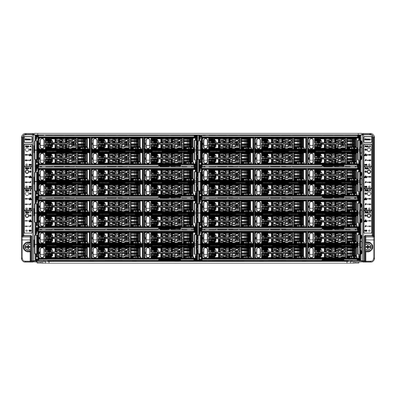
Backplane/Drives As a system, the FatTwin F619P2-RT/RTN/RC0/RC1 supports the use of six (6) 2.5" drives in front-mounted hot-swap drive trays per node (type of drive varies by model), for a total of forty-eight (48) HDD drives in the system. Each of the eight backplanes works to apply system- based control for power and fan speed functions, yet at the same time logically connects a set of six 2.5"... -
Page 11: System Features
FatTwin F619P2-RT/RTN/RC0/RC1 User's Manual 1.4 System Features The following table provides you with an overview of the main features of the F619P2-RT/RTN/RC0/RC1. Please refer to Appendix C for additional specifications. System Features Motherboard X11DPFR-S/SN Chassis F418BC2-R2K20BP Dual Intel® Xeon® Scalable processors which offer 2 UPI (UltraPath Interconnect) of up to 10.4GT/s Note: Both CPUs need to be installed for full access to the PCI-E slots, DIMM slots, and onboard controllers. -
Page 12: Server Chassis Features
Chapter 1: Introduction 1.5 Server Chassis Features Control Panel The switches and LEDs located on the control panel are described below. See Chapter 4 for details on the control panel connections. Figure 1-1. Control Panel View Control Panel Features Item Feature Description The main power button on each of the eight control panels is used to apply... -
Page 13: Front Features
FatTwin F619P2-RT/RTN/RC0/RC1 User's Manual Information LED Status Description Continuously on and red An overheat condition has occurred. (This may be caused by cable congestion.) Blinking red (1 Hz) Fan failure: check for an inoperative fan. Blinking red (0.25 Hz) Power failure: check for an inoperative power supply. -
Page 14: Rear Features
Chapter 1: Introduction Rear Features The illustration below shows the features included on the rear of the chassis. Figure 1-3. Chassis Rear View Rear Chassis Features Item Feature Description Power Supply Four (4) redundant 2200 Watt power supplies are at rear of the chassis Rear I/O Ports Each node has its own rear I/O ports. -
Page 15: Motherboard Layout
FatTwin F619P2-RT/RTN/RC0/RC1 User's Manual 1.6 Motherboard Layout Below is a layout of the X11DPFR-S/SN with jumper, connector and LED locations shown. See the table on the following page for descriptions. For detailed descriptions, pinout information and jumper settings, refer to Chapter 4. -
Page 16: Quick Reference Table
Chapter 1: Introduction Quick Reference Table Jumper Description Default Setting JBT1 Clear CMOS Open (Normal) JPME1 ME Recovery Pins 1-2 (Normal) JVRM1 VRM SMB Clock (to BMC or PCH) Pins 1-2 (BMC, Normal) JVRM2 VRM SMB Data (to BMC or PCH) Pins 1-2 (BMC, Normal) Connector Description... - Page 17 Chapter 1: Introduction VCCP0 12v VCCP1 12v VR13 VR13 5+1 PHASE 5+1 PHASE 165W 165W 10.4/11.2G PCI-E X16 PCI-E X8 PCI-E X4 X4 X4 X4 PCI-E X16 PCI-E x16 PCI-E X8 DMI3 6.0 Gb/S S-SATA x2 SIOM PCI-E X1 NCSI SATA 6.0 Gb/S Intel PCH...
-
Page 18: Overview
FatTwin F619P2-RT/RTN/RC0/RC1 User's Manual Chapter 2 Server Installation 2.1 Overview This chapter provides advice and instructions for mounting your system in a server rack. If your system is not already fully integrated with processors, system memory etc., refer to Chapter 4 for details on installing those specific components. -
Page 19: Server Precautions
Chapter 2: Server Installation • In single rack installations, stabilizers should be attached to the rack. In multiple rack in- stallations, the racks should be coupled together. • Always make sure the rack is stable before extending a server or other component from the rack. -
Page 20: Circuit Overloading
FatTwin F619P2-RT/RTN/RC0/RC1 User's Manual Circuit Overloading Consideration should be given to the connection of the equipment to the power supply circuitry and the effect that any possible overloading of circuits might have on overcurrent protection and power supply wiring. Appropriate consideration of equipment nameplate ratings should be used when addressing this concern. -
Page 21: Installing The Rails
Chapter 2: Server Installation 2.3 Installing the Rails There are a variety of rack units on the market, which may require a slightly different assembly procedure. The following is a basic guideline for installing the system into a rack with the rack mounting hardware provided. -
Page 22: Installing The Chassis Rails
FatTwin F619P2-RT/RTN/RC0/RC1 User's Manual Installing the Chassis Rails Begin the rack mounting procedure by installing the inner rails to the server chassis. 1. Position the front and rear chassis rail sections along the side of the server making sure the screw holes line up. Note that these two rails are left/right specific. -
Page 23: Installing The Rack Rails
Chapter 2: Server Installation Installing the Rack Rails Determine where you want to place the server in the rack (see the Rack and Server Precautions in Section 2.2). Note that servers should always be installed to the bottom of a rack first for stability reasons. -
Page 24: Removing Power
FatTwin F619P2-RT/RTN/RC0/RC1 User's Manual Chapter 3 Maintenance and Component Installation This chapter provides instructions on installing and replacing main system components. To prevent compatibility issues, only use components that match the specifications and/or part numbers given. Installation or replacement of most components require that power first be removed from the system. -
Page 25: Chassis Components
Chapter 3: Maintenance and Component Installation 3-2 Chassis Components The chassis includes power supplies, rear I/O ports, expansion card slots and eight nodes. Each node is a separate system containing a drawer with a serverboard, fans, and other components. Each node may be removed from the chassis separately. Installing and Removing the Node Drawers The F418BC2 chassis contains eight individual motherboards in separate node drawers (Figure 3-1). -
Page 26: Removing Nodes From The Chassis
FatTwin F619P2-RT/RTN/RC0/RC1 User's Manual Removing Nodes from the Chassis Each of the eight individual nodes may be removed from the chassis. Note that when a node is removed from the chassis, the hard drives located in the node will shut-down. -
Page 27: Removing The Cover From The Node
Chapter 3: Maintenance and Component Installation Removing the Cover from the Node Removing the Node Cover 1. Remove the screw on the rear of the node. 2. Lift the cover up and off the node. Figure 3-3. Removing the Node Cover... -
Page 28: Node Configurations
FatTwin F619P2-RT/RTN/RC0/RC1 User's Manual Node Configurations Overview of the Node Node configuration for a typical node is shown below in Figure 3-4. Front of Rear of the Node the Node Figure 3-4. Front and Rear of the Node F418BC2 Node Layout The specifications for the F418BC2 nodes are shown in the table below and shown in Figure 3-5. -
Page 29: Nodes And Associated Hard Drives
Chapter 3: Maintenance and Component Installation Nodes and Associated Hard Drives The F418BC2 chassis contains eight individual motherboards in separate nodes. Each node controls the hard drives contained within that node. Note that if a node is pulled out of the chassis, the hard drives associated with that node will power down as well. -
Page 30: Installing And Removing 2.5" Hard Drives
FatTwin F619P2-RT/RTN/RC0/RC1 User's Manual Installing and Removing 2.5" Hard Drives Removing 2.5" Hard Drive Carriers from the Node 1. Press the release button on the drive carrier. This extends the drive bay handle. 2. Use the handle to pull the drive carrier out of the chassis. - Page 31 The hard drives are hot-swappable and may be removed from the node without removing the node from the chassis or powering down the system. Caution: Enterprise level hard disk drives are recommended for use in Supermicro chas- sis and servers. For information on recommended HDDs, visit the Supermicro website...
- Page 32 FatTwin F619P2-RT/RTN/RC0/RC1 User's Manual Figure 3-9. Removing the Dummy Drive from the 2.5" Drive Carrier Hard Drive 2.5" Drive Carrier Figure 3-10. Installing a 2.5" Hard Drive in the Drive Carrier...
-
Page 33: Removing And Installing The Backplane
Chapter 3: Maintenance and Component Installation Removing and Installing the Backplane The F418BC2 chassis backplane is located behind the hard drives and in front of the front system fans in each node. Although backplane failure rarely occurs, in the event of a backplane failure, follow the instructions below. -
Page 34: Installing The Backplane
FatTwin F619P2-RT/RTN/RC0/RC1 User's Manual Figure 3-12. Removing the Backplane from the Node Installing the Backplane Installing the Backplane into the Chassis 1. Ensure that all of the hard drive carriers have been removed from the bays in the front of the node. -
Page 35: Installing The Serverboard
Installing the Serverboard Compatible Motherboards For the most up-to-date information on compatible motherboards and other parts, visit the Supermicro website at www.supermicro.com. Permanent and Optional Standoffs Standoffs prevent short circuits by creating space between the serverboard and the floor of the node. - Page 36 FatTwin F619P2-RT/RTN/RC0/RC1 User's Manual 7. Connect the cables between the serverboard, backplane, chassis, front panel, and power supply, as needed. The fans may be temporarily removed to allow access to the backplane ports. 8. Replace the expansion card bracket and secure the bracket with a screw.
-
Page 37: Installing Expansion Cards
Chapter 3: Maintenance and Component Installation Installing Expansion Cards F418BC2 PCI-E Slot Configurations Some F418BC2 chassis models support one or more expansion cards in each node. Refer to the tables below to determine the PCI-E slot configuration for your particular chassis. F418BC2-R2K20BP Front of Node Rear of Node... -
Page 38: Expansion Card Installation
FatTwin F619P2-RT/RTN/RC0/RC1 User's Manual Expansion Card Installation Each node supports one expansion card. This expansion card must be plugged into a riser card, which in turn plugs into the serverboard. Assembling the PCI-E Slot Bracket 1. Remove the (3) mounting screws securing the PCI-E bracket to the node. - Page 39 Chapter 3: Maintenance and Component Installation PCI-E Slot Bracket Riser Card Figure 3-17. Installing the PCI-E Slot Bracket Assembly...
-
Page 40: Installing A Siom Module
FatTwin F619P2-RT/RTN/RC0/RC1 User's Manual Installing a SIOM Module Each node in the system has one front mounted SIOM module, which adds various I/O ports to the node, depending upon the module selected. To install a module, use the procedure below. -
Page 41: Installing Air Shrouds
Chapter 3: Maintenance and Component Installation Installing Air Shrouds Air shrouds concentrate airflow to maximize fan efficiency. The F418BC2 chassis requires a two-piece air shroud in each node. Installing an Air Shroud 1. Make sure that the serverboard and all components are properly installed in each node. 2. -
Page 42: Removing And Installing System Fans
FatTwin F619P2-RT/RTN/RC0/RC1 User's Manual Removing and Installing System Fans The F418BC2 chassis includes three (3) 4-cm cooling fans per node for a total of twenty-four (24) per system. These fans are NOT redundant, hot-plug and must be replaced when they fail. -
Page 43: Replacing The Power Supplies
The F418BC2 chassis utilizes redundant, hot-plug power supplies.. In the unlikely event that the power supply unit needs to be replaced, one power supply can be removed, without powering down the system. Replacement units can be ordered directly from Supermicro. Changing the Power Supply 1. - Page 44 FatTwin F619P2-RT/RTN/RC0/RC1 User's Manual Release Tab Figure 3-22. Changing the F418BC2 Chassis Power Supplies...
-
Page 45: Motherboard Components
CPU socket cap is in place and none of the socket pins are bent; otherwise, contact your retailer immediately. • Refer to the Supermicro website for updates on CPU support. The Processor Intel® Xeon® Scalable processors Note: All graphics, drawings and pictures shown in this manual are for illustration only. -
Page 46: Overview Of The Processor Socket Assembly
FatTwin F619P2-RT/RTN/RC0/RC1 User's Manual Overview of the Processor Socket Assembly The processor socket assembly contains 1) the Intel® Xeon® Scalable processors processor 2) CPU/heatsink carrier, 3) dust cover, and 4) CPU socket. The Intel® Xeon® Scalable processors Processor 2. CPU/Heatsink Carrier 3. -
Page 47: Overview Of The Processor Heatsink Module
Chapter 3: Maintenance and Component Installation Overview of the Processor Heatsink Module The processor heatsink module (PHM) contains 1) a passive heatsink, 2) a CPU/heatsink carrier, and 3) The Intel® Xeon® Scalable processors processor. 1. Passive Heatsink 2. CPU/Heatsink Carrier 81xx/61xx/51xx/41xx/31xx Processor Processor Heatsink Module (Bottom View) -
Page 48: Preparing The Cpu Socket For Installation
FatTwin F619P2-RT/RTN/RC0/RC1 User's Manual Preparing the CPU Socket for Installation This motherboard comes with the CPU socket pre-assembled in the factory. The CPU socket contains 1) a dust cover, 2) a socket bracket, 3) the CPU (LGA3647) socket, and 4) a back plate. -
Page 49: Attaching The Processor To The Cpu/Heatsink Carrier
Chapter 3: Maintenance and Component Installation Attaching the Processor to the CPU/Heatsink Carrier To properly install the CPU onto the CPU/heatsink carrier, please follow the steps below. Installing the CPU onto the CPU/heatsink 1. Locate Pin 1 (Notch A), Notch B, and Notch C on the CPU and locate Pin 1 (Notch A), Notch B, and Notch C on the CPU/heatsink carrier. -
Page 50: Heatsink Module (Phm)
FatTwin F619P2-RT/RTN/RC0/RC1 User's Manual Attaching the CPU/Carrier Assembly to the Passive Heatsink to Form the Processor Heatsink Module (PHM) After you have made a CPU/carrier assembly, please follow the steps below to mount the assembly onto the heatsink to create the Processor Heatsink Module (PHM). -
Page 51: Installing The Processor Heatsink Module (Phm)
Chapter 3: Maintenance and Component Installation Installing the Processor Heatsink Module (PHM) 1. Once you have assembled the processor heatsink module (PHM) by following the instructions listed on the previous page, align the processor heatsink module with the CPU socket on the motherboard. 2. -
Page 52: Removing The Processor Heatsink Module (Phm)
FatTwin F619P2-RT/RTN/RC0/RC1 User's Manual Removing the Processor Heatsink Module (PHM) Before starting to remove the processor heatsink module (PHM), unplug power cord from the power outlet. 1. Using a T30-size star driver, turn the screws on the PHM counterclockwise to loosen it from the socket, starting with screw marked #4 (in the sequence of 4, 3, 2, 1). -
Page 53: Memory Support And Installation
Chapter 3: Maintenance and Component Installation Memory Support and Installation Note: Check the Supermicro website for recommended memory modules. Important: Exercise extreme care when installing or removing DIMM modules to prevent any damage. Memory Support The X11DPFR-S(N) supports up to 1536 GB of LRDIMM, Registered DIMM (RDIMM), and Non-Volatile DIMM (NV-DIMM) DDR4 (288-pin) ECC 2666/2400/2133 Mhz modules in twelve (12) slots. - Page 54 FatTwin F619P2-RT/RTN/RC0/RC1 User's Manual General Population Requirements DIMM Mixing Rules • All DIMMs must be DDR4 DIMMs only. • X4 and X8 DIMMs can be mixed in the same channel. • Mixing of LRDIMMs and RDIMMs is not allowed in the same channel, across different channels, and across different sockets.
- Page 55 Chapter 3: Maintenance and Component Installation DDR4 Only 2SPC Memory Configuration with x8 DIMMs Total # of DDR Channel Number Virtual DIMMs of Ranks Lock Step DIMM Population 1 x8 DIMM Must be installed on iMC0 DDR Channel 0 within an IMC >1 SVLS (Note: Uniformly...
- Page 56 FatTwin F619P2-RT/RTN/RC0/RC1 User's Manual DDR4 Only 2SPC Memory Configuration with x4 DIMMs Total # of DDR Channel Number Adaptive DIMMs of Ranks Virtual Lock Step DIMM Population 1 x4 DIMM Must be installed on iMC0 DDR Channel 0 Y, only Bank VLS within an IMC >1...
-
Page 57: Dimm Installation
Chapter 3: Maintenance and Component Installation DIMM Installation UID_LED1 1. Insert DIMM modules in the following order: For USB0/1 (3.0) IPMI_LAN1 COM1 CPU1, begin with P1-DIMMC1, P1-DIMMB1, LED1 BMC_HB_LED1 P1-DIMMA1 then P1-DIMMF1, P1-DIMME1, BIOS JPP1/JTAG SCAN JSIOM1 JPP0/JTAG SCAN P1-DIMMD1. For CPU2, begin with P2-DIMMC1, JSDCARD1 P2-DIMMB1, P2-DIMMA1 then P2-DIMMF1, P2- JBT1... -
Page 58: Motherboard Battery
FatTwin F619P2-RT/RTN/RC0/RC1 User's Manual Motherboard Battery The motherboard uses non-volatile memory to retain system information when system power is removed. This memory is powered by a lithium battery residing on the motherboard. Replacing the Battery Begin by removing power from the system as described in section 3.1. -
Page 59: Power Connections
Chapter 4: Motherboard Connections Chapter 4 Motherboard Connections This section describes the connections on the motherboard and provides pinout definitions. Note that depending on how the system is configured, not all connections are required. The LEDs on the motherboard are also described here. A severboard layout indicating component locations may be found in Chapter 1. - Page 60 FatTwin F619P2-RT/RTN/RC0/RC1 User's Manual TPM Header The JTPM1 header is used to connect a Trusted Platform Module (TPM)/Port 80, which is available from a third-party vendor. A TPM/Port 80 connector is a security device that supports encryption and authentication in hard drives. It allows the motherboard to deny access if the TPM associated with the hard drive is not installed in the system.
-
Page 61: Rear I/O Ports
Chapter 4: Motherboard Connections 4.3 Rear I/O Ports See the figure below for the locations and descriptions of the various I/O ports on the rear of the motherboard. UID_LED1 USB0/1 (3.0) IPMI_LAN1 COM1 LED1 BMC_HB_LED1 BIOS JPP1/JTAG SCAN JSIOM1 JPP0/JTAG SCAN JSDCARD1 JBT1 JRK1... -
Page 62: Ethernet Ports
Note: UID can also be triggered via IPMI on the motherboard. For more information on IPMI, please refer to the IPMI User's Guide posted on our website at http://www.supermicro.com. UID LED... -
Page 63: Front Control Panel
Chapter 4: Motherboard Connections 4.4 Front Control Panel JF1 contains header pins for various control panel connections. See the figure below for the pin locations and definitions of the control panel buttons and LED indicators. All JF1 wires have been bundled into a single cable to simplify this connection. Make sure the red wire plugs into pin 1 as marked on the motherboard. - Page 64 FatTwin F619P2-RT/RTN/RC0/RC1 User's Manual Power Fail LED The Power Fail LED connection is located on pins 5 and 6 of JF1. Refer to the table below for pin definitions. Power Fail LED Pin Definitions (JF1) Pin# Definition 3.3V PWR Supply Fail...
- Page 65 Chapter 4: Motherboard Connections Power LED The Power LED connection is located on pins 15 and 16 of JF1. Refer to the table below for pin definitions. Power LED Pin Definitions (JF1) Pins Definition 3.3V PWR LED NMI Button The non-maskable interrupt (NMI) button header is located on pins 19 and 20 of JF1. Refer to the table below for pin definitions.
-
Page 66: Jumpers
FatTwin F619P2-RT/RTN/RC0/RC1 User's Manual 4.5 Jumpers Explanation of Jumpers To modify the operation of the motherboard, jumpers are used to choose between optional settings. Jumpers create shorts between two pins to change the function associated with it. Pin 1 is identified with a square solder pad on the printed circuit board. See the motherboard layout page for jumper locations. - Page 67 Chapter 4: Motherboard Connections VGA Enable/Disable JPG1 allows you to enable or disable the VGA port using the onboard graphics controller. The default setting is Enabled. VGA Enable/Disable Jumper Settings Jumper Setting Definition Pins 1-2 Enabled Pins 2-3 Disabled Management Engine (ME) Recovery Use jumper JPME1 to select ME Firmware Recovery mode, which will limit resource allocation for essential system operation only in order to maintain normal power operation and management.
-
Page 68: Led Indicators
FatTwin F619P2-RT/RTN/RC0/RC1 User's Manual 4.6 LED Indicators IPMI LAN LEDs A dedicated IPMI LAN, located on the back panel, has two LED indicators. The amber LED on the right of the IPMI LAN port indicates activity, while the LED on the left indicates the speed of the connection. -
Page 69: Pci-E 3.0 Slots
Chapter 4: Motherboard Connections 4.7 PCI-E 3.0 Slots PCI-E 3.0 Slots There are several PCI-E slots located on the motherboard. Refer to the layout below for their locations. 1. PCI-E 3.0 x16 Right Riser Card (JSXB1) 2. PCI-E 3.0 x16 (x8+x8) SMCI Proprietary slot (JSXB2) 3. -
Page 70: Os Installation
You must first configure RAID settings (if using RAID) before you install the Windows OS and the software drivers. To configure RAID settings, please refer to the RAID Configuration User Guides posted on our website at www.supermicro.com/support/manuals. Installing the Windows OS for a RAID System 1. -
Page 71: Driver Installation
Chapter 5: Software 5.2 Driver Installation The Supermicro FTP site contains drivers and utilities for your system at ftp://ftp.supermicro. com. Some of these must be installed, such as the chipset driver. After accessing the FTP site, go into the CDR_Images directory and locate the ISO file for your motherboard. -
Page 72: Superdoctor ® 5
5.3 SuperDoctor ® The Supermicro SuperDoctor 5 is a program that functions in a command-line or web-based interface for Windows and Linux operating systems. The program monitors such system health information as CPU temperature, system voltages, system power consumption, fan speed, and provides alerts via email or Simple Network Management Protocol (SNMP). -
Page 73: Ipmi
The X11DPFR-S/SN support the Intelligent Platform Management Interface (IPMI). IPMI is used to provide remote access, monitoring and management. There are several BIOS settings that are related to IPMI. For general documentation and information on IPMI, please visit our website at: http://www.supermicro.com/products/nfo/IPMI.cfm. -
Page 74: Starting The Setup Utility
FatTwin F619P2-RT/RTN/RC0/RC1 User's Manual Chapter 6 BIOS 6.1 Introduction This chapter describes the AMIBIOS™ Setup utility for the X11DPFR-S/SN motherboard(s). This is stored in a flash chip and can be easily upgraded using a floppy disk-based program. Note: Due to periodic changes to the BIOS, some settings may have been added or deleted and might not yet be recorded in this manual. -
Page 75: Main Menu
Chapter 6: BIOS 6.2 Main Menu When you first enter AMI BIOS Setup Utility, you will see the Main Menu screen.You can always return to the Main Menu by selecting the Main tab on the top of the screen with the arrow keys. - Page 76 FatTwin F619P2-RT/RTN/RC0/RC1 User's Manual Note: The time is in the 24-hour format. For example, 5:30 P.M. appears as 17:30:00. The date's default value is 01/01/2014 after RTC reset. Supermicro X11DPFR-S(N) BIOS Version This item displays the version of the BIOS ROM used in the system.
-
Page 77: Advanced Settings Menu
Chapter 6: BIOS 6.3 Advanced Settings Menu Use the arrow keys to select the Advanced submenu and press <Enter> to access the submenu items: Warning: Take Caution when changing the Advanced settings. An incorrect value, an incorrect DRAM frequency, or an incorrect BIOS timing setting may cause the system to malfunction. When this occurs, restore the setting to the manufacture default setting. -
Page 78: Power Configuration
FatTwin F619P2-RT/RTN/RC0/RC1 User's Manual Option ROM Messages Use this feature to set the display mode for the Option ROM. Select Keep Current to use the current AddOn ROM display setting. Select Force BIOS to use the Option ROM display mode set by the system BIOS. The options are Force BIOS and Keep Current. -
Page 79: Cpu Configuration
Chapter 6: BIOS Restore on AC Power Loss Use this feature to set the power state after a power outage. Select Stay Off for the system power to remain off after a power loss. Select Power On for the system power to be turned on after a power loss. - Page 80 FatTwin F619P2-RT/RTN/RC0/RC1 User's Manual Hyper-Threading (ALL) Select Enable to use Intel Hyper-Threading Technology to enhance CPU performance. The options are Enable and Disable. Execute Disable Bit (Available if supported by the OS & the CPU) Select Enable to enable Execute Disable Bit support which will allow the processor to...
-
Page 81: Advanced Power Management Configuration
Chapter 6: BIOS LLC Prefetch If this feature is set to Enable, LLC (hardware cache) prefetching on all threads will be supported. The options are Disable and Enable. Extended APIC (Extended Advanced Programmable Interrupt Controller) Based on the Intel Hyper-Threading technology, each logical processor (thread) is assigned 256 APIC IDs (APIDs) in 8-bit bandwidth. - Page 82 FatTwin F619P2-RT/RTN/RC0/RC1 User's Manual Hardware PM (Power Management) State Control Hardware P-States If this feature is set to Disable, hardware will choose a P-state setting for the system based on an OS request. If this feature is set to Native Mode, hardware will choose a P-state setting based on OS guidance.
-
Page 83: Chipset Configuration
Chapter 6: BIOS Chipset Configuration Warning: Setting the wrong values in the following sections may cause the system to malfunc- tion. North Bridge This feature allows the user to configure the settings for the Intel North Bridge. UPI (Ultra Path Interconnect) Configuration This section displays the following UPI General Configuration information: •... - Page 84 FatTwin F619P2-RT/RTN/RC0/RC1 User's Manual Sub NUMA Clustering (SNC) is a feature that breaks up the Last Level Cache (LLC) into clusters based on address range. Each cluster is connected to a subset of the memory controller. Enabling SNC improves average latency and reduces memory access congestion to achieve higher performance.
-
Page 85: Memory Configuration
Chapter 6: BIOS Memory Configuration Enforce POR Select POR to enforce POR restrictions for DDR4 memory frequency and voltage programming. The options are POR and Disable. Memory Frequency Use this feature to set the maximum memory frequency for onboard memory modules. The options are Auto, 1866, 2000, 2133, 2200, 2400, 2600, and 2666. - Page 86 FatTwin F619P2-RT/RTN/RC0/RC1 User's Manual Memory Topology This item displays the information of onboard memory modules as detected by the BIOS. • P1 DIMMA1 • P1 DIMMB1 • P1 DIMMC1 • P1 DIMMD1 • P1 DIMME1 • P1 DIMMF1 • P2 DIMMA1 •...
-
Page 87: Iio Configuration
Chapter 6: BIOS Correctable Error Threshold Use this item to enter the threshold value for correctable memory errors. The default setting is 10. SDDC Plus One Select Enable for SDDC (Single Device Data Correction) support, which will increase the reliability and serviceability of your system memory. The options are Enable and Disable. ADDDC (Adaptive Double Device Data Correction) Sparing Select Enable for ADDDC sparing support to enhance memory performance. - Page 88 FatTwin F619P2-RT/RTN/RC0/RC1 User's Manual MCP0 (II0 PCIe Br4) This item configures the PCI-E port Bifuraction setting for a PCI-E port specified by the user. The options are x4x4x4x4, x4x4x8, x8x4x4, x8x8, x16, and Auto. MCP1 (II0 PCIe Br5) This item configures the PCI-E port Bifuraction setting for a PCI-E port specified by the user.
- Page 89 Chapter 6: BIOS CPU2 PcieBr1D00F0 - Port 1A/Socket 1 PcieBr2D00F0 - Port 2A/Socket 1 PcieBr3D00F0 - Port 3A/Socket 1 PcieBr4D00F0 - MCP 0/Socket 1 PcieBr5D00F0 - MCP 1 Link Speed Use this item to select the link speed for the PCI-E port specified by the user. The op- tions are Auto, Gen 1 (2.5 GT/s), Gen 2 (5 GT/s), and Gen 3 (8 GT/s).
- Page 90 FatTwin F619P2-RT/RTN/RC0/RC1 User's Manual Interrupt Remapping Select Enable for Interrupt Remapping support to enhance system performance. The options are Enable and Disable. PassThrough DMA Select Enable for the Non-Iscoh VT-d engine to pass through DMA (Direct Memory Access) to enhance system performance. The options are Enable and Disable.
- Page 91 Chapter 6: BIOS Hot Plug Capable (Available when the device is detected by the system) Use this feature to enable hot plug support for PCIe root ports 1A~1D. The options are Disable and Enable. VMD Config for PStack1 Intel® VMD for Volume Management Device Select Enable to use the Intel Volume Management Device Technology for this stack.
-
Page 92: South Bridge
FatTwin F619P2-RT/RTN/RC0/RC1 User's Manual Intel® VMD for Volume Management Device on CPU2 VMD Config for PStack2 Intel® VMD for Volume Management Device Select Enable to use the Intel Volume Management Device Technology for this stack. The options are Disable and Enable. -
Page 93: Pch Sata Configuration
Chapter 6: BIOS Port 60/64 Emulation Select Enabled for I/O port 60h/64h emulation support, which in turn, will provide complete legacy USB keyboard support for the operating systems that do not support legacy USB devices. The options are Enabled and Disabled. Server ME (Management Engine) Configuration This feature displays the following system ME configuration settings. - Page 94 FatTwin F619P2-RT/RTN/RC0/RC1 User's Manual Aggressive Link Power Management When this item is set to Enabled, the SATA AHCI controller manages the power use of the SATA link. The controller will put the link in a low power mode during an extended period of I/O inactivity, and will return the link to an active state when I/O activity resumes.
- Page 95 Chapter 6: BIOS SATA/sSATA RAID Boot Select (Available when the item "Configure SATA as" is set to "RAID") This feature allows the user to decide which controller should be used for system boot. The options are None, SATA Controller, sSATA Controller, and Both. Support Aggressive Link Power Management When this item is set to Enable, the sSATA AHCI controller manages the power use of the SATA link.
- Page 96 FatTwin F619P2-RT/RTN/RC0/RC1 User's Manual SR-IOV Support (Available if the system supports Single-Root Virtualization) Select Enabled for Single-Root IO Virtualization support. The options are Enabled and Disabled. MMIOHBase Use this item to select the base memory size according to memory-address mapping for the IO hub.
- Page 97 Chapter 6: BIOS CPU1 PCI-E 3.0 x16/1U Riser OPROM Use this feature to select which firmware type to be loaded for the add-on card in this slot. The options are Disabled, Legacy, and EFI. CPU1 JSXB2 PCI-E 3.0 x8 OPROM Use this feature to select which firmware type to be loaded for the add-on card in this slot.
-
Page 98: Network Stack Configuration
FatTwin F619P2-RT/RTN/RC0/RC1 User's Manual Onboard Video Option ROM Use this item to select the Onboard Video Option ROM type. The options are Disabled, Legacy, and EFI. Network Stack Configuration Network Stack Select Enabled to enable PXE (Preboot Execution Environment) or UEFI (Unified Extensible Firmware Interface) for network stack support. -
Page 99: Super Io Configuration
Chapter 6: BIOS Super IO Configuration Super IO Chip AST2500 Serial Port 1 Configuration Serial Port Select Enabled to enable the onboard serial port specified by the user. The options are Enabled and Disabled. Device Settings This item displays the base I/O port address and the Interrupt Request address of a serial port specified by the user. -
Page 100: Serial Port Console Redirection
FatTwin F619P2-RT/RTN/RC0/RC1 User's Manual Serial Port 2 Attribute Select SOL to use COM Port 2 as a Serial_Over_LAN (SOL) port for console redirection. The options are COM and SOL. Serial Port Console Redirection COM 1 Console Redirection Select Enabled to enable COM Port 1 for Console Redirection, which will allow a client machine to be connected to a host machine at a remote site for networking. - Page 101 Chapter 6: BIOS Flow Control Use this feature to set the flow control for Console Redirection to prevent data loss caused by buffer overflow. Send a "Stop" signal to stop sending data when the receiving buffer is full. Send a "Start" signal to start sending data when the receiving buffer is empty. The options are None and Hardware RTS/CTS.
- Page 102 FatTwin F619P2-RT/RTN/RC0/RC1 User's Manual Console Redirection Settings (for SOL/COM2) Use this feature to specify how the host computer will exchange data with the client computer, which is the remote computer used by the user. Terminal Type Use this feature to select the target terminal emulation type for Console Redirection.
- Page 103 Chapter 6: BIOS Recorder Mode Select Enabled to capture the data displayed on a terminal and send it as text messages to a remote server. The options are Disabled and Enabled. Resolution 100x31 Select Enabled for extended-terminal resolution support. The options are Disabled and Enabled.
-
Page 104: Acpi Settings
FatTwin F619P2-RT/RTN/RC0/RC1 User's Manual EMS Console Redirection Settings Out-of-Band Management Port The feature selects a serial port in a client server to be used by the Windows Emergency Management Services (EMS) to communicate with a remote host server. The options are COM1 (Console Redirection) and COM2/SOL (Console Redirection). - Page 105 Chapter 6: BIOS High Precision Timer Select Enabled to activate the High Precision Event Timer (HPET) that produces periodic interrupts at a much higher frequency than a Real-time Clock (RTC) does in synchronizing multimedia streams, providing smooth playback and reducing the dependency on other timestamp calculation devices, such as an x86 RDTSC Instruction embedded in the CPU.
-
Page 106: Trusted Computing
FatTwin F619P2-RT/RTN/RC0/RC1 User's Manual 6.4 Trusted Computing When a TPM (Trusted-Platform Module) device is detected in your machine, the following information will be displayed. • TPM2.0 Device Found • Vendor • Firmware Version Security Device Support If this feature and the TPM jumper (JPT1) on the motherboard are both enabled, the onboard security (TPM) device will be enabled in the BIOS to enhance data integrity and system security. - Page 107 Chapter 6: BIOS Pending Operation Use this feature to schedule a TPM-related operation to be performed by a security (TPM) device at the next system boot to enhance system data integrity. Your system will reboot to carry out a pending TPM operation. The options are None and TPM Clear. Note: Your system will reboot to carry out a pending TPM operation.
-
Page 108: Iscsi Configuration
FatTwin F619P2-RT/RTN/RC0/RC1 User's Manual Note 2: For more information on TPM, please refer to the TPM manual at http://www. supermicro.com/manuals/other. iSCSI Configuration iSCSI Initiator Name This feature allows the user to enter the unique name of the iSCSI Initiator in IQN format. -
Page 109: Event Logs
Chapter 6: BIOS 6.5 Event Logs Use this feature to configure Event Log settings. Change SMBIOS Event Log Settings Enabling/Disabling Options SMBIOS Event Log Select Enabled to enable SMBIOS (System Management BIOS) Event Logging during system boot. The options are Enabled and Disabled. Erasing Settings Erase Event Log Select Enabled to erase all error events in the SMBIOS (System Management BIOS) log... -
Page 110: View System Event Log
FatTwin F619P2-RT/RTN/RC0/RC1 User's Manual When Log is Full Select Erase Immediately to immediately erase all errors in the SMBIOS event log when the event log is full. Select Do Nothing for the system to do nothing when the SMBIOS event log is full. -
Page 111: Ipmi
Chapter 6: BIOS 6.6 IPMI Use this feature to configure Intelligent Platform Management Interface (IPMI) settings. When you select this submenu and press the <Enter> key, the following information will display: • IPMI Firmware Revision: This item indicates the IPMI firmware revision used in your system. •... -
Page 112: Bmc Network Configuration
FatTwin F619P2-RT/RTN/RC0/RC1 User's Manual Erasing Settings Erase SEL Select Yes, On next reset to erase all system event logs upon next system reboot. Select Yes, On every reset to erase all system event logs upon each system reboot. Select No to keep all system event logs after each system reboot. - Page 113 Chapter 6: BIOS Configuration Address Source This feature allows the user to select the source of the IP address for this computer. If Static is selected, you will need to know the IP address of this computer and enter it to the system manually in the field.
- Page 114 FatTwin F619P2-RT/RTN/RC0/RC1 User's Manual *If the item above is set to Static, the following items will become available for configuration: • Station IPV6 Address • Prefix Length • IPV6 Router1 IP Address...
-
Page 115: Security Settings
Chapter 6: BIOS 6.7 Security Settings This menu allows the user to configure the following security settings for the system. Administrator Password Use this feature to set the administrator password which is required to enter the BIOS setup utility. The length of the password should be from 3 characters to 20 characters long. User Password Use this feature to set the user password which is required to enter the BIOS setup utility. -
Page 116: Secure Boot
FatTwin F619P2-RT/RTN/RC0/RC1 User's Manual Secure Boot When you select this submenu and press the <Enter> key, the following items will display: • System Mode • Secure Boot • Vendor Keys Attempt Secure Boot If this item is set to Enabled, Secure Boot will be activated when a Platform Key (PK) is entered. -
Page 117: Authorized Signatures
Chapter 6: BIOS Key Exchange Keys This feature allows the user to enter and configure a set of values to be used as a Key- Exchange-Keys for the system. This set of values also indicate the size, the keys numbers, and the key source of the Key-Exchange-Keys. -
Page 118: Boot Settings
FatTwin F619P2-RT/RTN/RC0/RC1 User's Manual 6.8 Boot Settings Use this feature to configure Boot Settings: Boot Mode Select Use this feature to select the type of devices that the system is going to boot from. The options are Legacy, UEFI (Unified Extensible Firmware Interface), and Dual. -
Page 119: Delete Boot Option
Chapter 6: BIOS When the item above -"Boot Mode Select" is set to Legacy, the following items will be display for configuration: • Boot Option #1 - Boot Option #8 When the item above -"Boot Mode Select" is set to UEFI, the following items will be display for configuration: •... -
Page 120: Save Options
FatTwin F619P2-RT/RTN/RC0/RC1 User's Manual 6.9 Save & Exit Select the Save & Exit tab from the BIOS setup screen to configure the settings below. Save Options Discard Changes and Exit Select this option to quit the BIOS setup without making any permanent changes to the system configuration and reboot the computer. - Page 121 Chapter 6: BIOS Discard Changes Select this option and press <Enter> to discard all the changes and return to the AMI BIOS setup utility. Default Options Restore Optimized Defaults To set this feature, select Restore Defaults from the Exit menu and press <Enter> to load manufacturer default settings which are intended for maximum system performance but not for maximum stability.
-
Page 122: Bios Error Codes
FatTwin F619P2-RT/RTN/RC0/RC1 User's Manual Appendix A BIOS Error Codes A-1 BIOS Error Beep (POST) Codes During the POST (Power-On Self-Test) routines, which are performed each time the system is powered on, errors may occur. Non-fatal errors are those which, in most cases, allow the system to continue the boot-up process. - Page 123 When BIOS performs the Power On Self Test, it writes checkpoint codes to I/O port 0080h. If the computer cannot complete the boot process, a diagnostic card can be attached to the computer to read I/O port 0080h (Supermicro p/n AOC-LPC80-20). For information on AMI updates, please refer to http://www.ami.com/products/.
- Page 124 Supermicro's Technical Support department for assistance. Only certified technicians should attempt to install or configure components. Read this appendix in its entirety before installing or configuring components in the Supermicro chassis. These warnings may also be found on our website at http://www.supermicro.com/about/...
- Page 125 Appendix B: Standardized Warning Statements Warnung WICHTIGE SICHERHEITSHINWEISE Dieses Warnsymbol bedeutet Gefahr. Sie befinden sich in einer Situation, die zu Verletzungen führen kann. Machen Sie sich vor der Arbeit mit Geräten mit den Gefahren elektrischer Schaltungen und den üblichen Verfahren zur Vorbeugung vor Unfällen vertraut. Suchen Sie mit der am Ende jeder Warnung angegebenen Anweisungsnummer nach der jeweiligen Übersetzung in den übersetzten Sicherheitshinweisen, die zusammen mit diesem Gerät ausgeliefert wurden.
-
Page 126: Installation Instructions
FatTwin F619P2-RT/RTN/RC0/RC1 User's Manual . ٌ ا ك ً ف حالة و ٌ يك أى تتسبب ف اصابة جسذ ة ٌ هذا الزهز ع ٌ خطز !تحذ ز قبل أى تعول عىل أي هعذات،يك عىل علن بالوخاطز ال ا ٌجوة عي الذوائز... -
Page 127: Circuit Breaker
Appendix B: Standardized Warning Statements Warnung Vor dem Anschließen des Systems an die Stromquelle die Installationsanweisungen lesen. ¡Advertencia! Lea las instrucciones de instalación antes de conectar el sistema a la red de alimentación. Attention Avant de brancher le système sur la source d'alimentation, consulter les directives d'installation. .יש... - Page 128 FatTwin F619P2-RT/RTN/RC0/RC1 User's Manual Warnung Dieses Produkt ist darauf angewiesen, dass im Gebäude ein Kurzschluss- bzw. Überstromschutz installiert ist. Stellen Sie sicher, dass der Nennwert der Schutzvorrichtung nicht mehr als: 250 V, 20 A beträgt. ¡Advertencia! Este equipo utiliza el sistema de protección contra cortocircuitos (o sobrecorrientes) del edificio.
-
Page 129: Power Disconnection Warning
Appendix B: Standardized Warning Statements Power Disconnection Warning Warning! The system must be disconnected from all sources of power and the power cord removed from the power supply module(s) before accessing the chassis interior to install or remove system components. 電源切断の警告... -
Page 130: Equipment Installation
FatTwin F619P2-RT/RTN/RC0/RC1 User's Manual يجب فصم اننظاو من جميع مصادر انطاقت وإ ز انت سهك انكهرباء من وحدة امداد انطاقت قبم انىصىل إىن امنناطق انداخهيت نههيكم نتثبيج أو إ ز انت مكىناث الجهاز 경고! 시스템에 부품들을 장착하거나 제거하기 위해서는 섀시 내부에 접근하기 전에 반드시 전원... -
Page 131: Restricted Area
Appendix B: Standardized Warning Statements Attention Il est vivement recommandé de confier l'installation, le remplacement et la maintenance de ces équipements à des personnels qualifiés et expérimentés. !אזהרה .צוות מוסמך בלבד רשאי להתקין, להחליף את הציוד או לתת שירות עבור הציוד واملدربيه... - Page 132 FatTwin F619P2-RT/RTN/RC0/RC1 User's Manual Warnung Diese Einheit ist zur Installation in Bereichen mit beschränktem Zutritt vorgesehen. Der Zutritt zu derartigen Bereichen ist nur mit einem Spezialwerkzeug, Schloss und Schlüssel oder einer sonstigen Sicherheitsvorkehrung möglich. ¡Advertencia! Esta unidad ha sido diseñada para instalación en áreas de acceso restringido. Sólo puede obtenerse acceso a una de estas áreas mediante la utilización de una herramienta especial,...
-
Page 133: Battery Handling
Appendix B: Standardized Warning Statements Battery Handling Warning! There is the danger of explosion if the battery is replaced incorrectly. Replace the battery only with the same or equivalent type recommended by the manufacturer. Dispose of used batteries according to the manufacturer's instructions 電池の取り扱い... -
Page 134: Redundant Power Supplies
FatTwin F619P2-RT/RTN/RC0/RC1 User's Manual هناك خطر من انفجار يف حالة اسحبذال البطارية بطريقة غري صحيحة فعليل اسحبذال البطارية فقط بنفس النىع أو ما يعادلها مام أوصث به الرشمة املصنعة جخلص من البطاريات املسحعملة وفقا لحعليامت الرشمة الصانعة 경고! 배터리가 올바르게 교체되지 않으면 폭발의 위험이 있습니다. 기존 배터리와 동일하거나 제... - Page 135 Appendix B: Standardized Warning Statements ¡Advertencia! Puede que esta unidad tenga más de una conexión para fuentes de alimentación. Para cortar por completo el suministro de energía, deben desconectarse todas las conexiones. Attention Cette unité peut avoir plus d'une connexion d'alimentation. Pour supprimer toute tension et tout courant électrique de l'unité, toutes les connexions d'alimentation doivent être débranchées.
-
Page 136: Backplane Voltage
FatTwin F619P2-RT/RTN/RC0/RC1 User's Manual Backplane Voltage Warning! Hazardous voltage or energy is present on the backplane when the system is operating. Use caution when servicing. バックプレーンの電圧 システムの稼働中は危険な電圧または電力が、 バックプレーン上にかかっています。 修理する際には注意く ださい。 警告 当系统正在进行时,背板上有很危险的电压或能量,进行维修时务必小心。 警告 當系統正在進行時,背板上有危險的電壓或能量,進行維修時務必小心。 Warnung Wenn das System in Betrieb ist, treten auf der Rückwandplatine gefährliche Spannungen oder Energien auf. -
Page 137: Comply With Local And National Electrical Codes
Appendix B: Standardized Warning Statements هناك خطز مه التيار الكهزبايئ أوالطاقة املىجىدة عىل اللىحة عندما يكىن النظام يعمل كه حذ ر ا عند خدمة هذا الجهاس 경고! 시스템이 동작 중일 때 후면판 (Backplane)에는 위험한 전압이나 에너지가 발생 합니다. 서비스 작업 시 주의하십시오. Waarschuwing Een gevaarlijke spanning of energie is aanwezig op de backplane wanneer het systeem in gebruik is. -
Page 138: Product Disposal
FatTwin F619P2-RT/RTN/RC0/RC1 User's Manual תיאום חוקי החשמל הארצי !אזהרה .התקנת הציוד חייבת להיות תואמת לחוקי החשמל המקומיים והארציים تركيب املعدات الكهربائية يجب أن ميتثل للقىاويه املحلية والىطىية املتعلقة بالكهرباء 경고! 현 지역 및 국가의 전기 규정에 따라 장비를 설치해야 합니다. - Page 139 Appendix B: Standardized Warning Statements Attention La mise au rebut ou le recyclage de ce produit sont généralement soumis à des lois et/ou directives de respect de l'environnement. Renseignez-vous auprès de l'organisme compétent. סילוק המוצר !אזהרה .סילוק סופי של מוצר זה חייב להיות בהתאם להנחיות וחוקי המדינה التخلص...
- Page 140 FatTwin F619P2-RT/RTN/RC0/RC1 User's Manual Warnung Gefährlich Bewegende Teile. Von den bewegenden Lüfterblätter fern halten. Die Lüfter drehen sich u. U. noch, wenn die Lüfterbaugruppe aus dem Chassis genommen wird. Halten Sie Finger, Schraubendreher und andere Gegenstände von den Öffnungen des Lüftergehäuses entfernt.
- Page 141 Verbindungskabeln, Stromkabeln und/oder Adapater, die Ihre örtlichen Sicherheitsstandards einhalten. Der Gebrauch von anderen Kabeln und Adapter können Fehlfunktionen oder Feuer verursachen. Die Richtlinien untersagen das Nutzen von UL oder CAS zertifizierten Kabeln (mit UL/CSA gekennzeichnet), an Geräten oder Produkten die nicht mit Supermicro gekennzeichnet sind.
- Page 142 حجم املوصل والقابس السليم. استخدام أي كابالت ومحوالت أخرى قد يتسبب يف عطل أو حريق. يحظر قانون السالمة لألجهزة الكهربائية واملعدات استخدام الكابالت املعتمدة من قبلUL أوCSA ( والتي تحمل عالمةUL/CSA) مع أي معدات أخرى غري املنتجات املعنية واملحددة من قبلSupermicro.
- Page 143 사항을 준수하여 제공되거나 지정된 연결 혹은 구매 케이블, 전원 케이블 및 AC 어댑터를 사용하십시오. 다른 케이블이나 어댑터를 사용하면 오작동이나 화재가 발생할 수 있습니다. 전기 용품 안전법은 UL 또는 CSA 인증 케이블 (코드에 UL / CSA가 표시된 케이블)을 Supermicro 가 지정한 제품 이외의 전기 장치에 사용하는 것을 금지합니다. Stroomkabel en AC-Adapter...
-
Page 144: System Specifications
FatTwin F619P2-RT/RTN/RC0/RC1 User's Manual Appendix C System Specifications Processors Dual Intel® Xeon® Scalable processors in an Socket P type socket Note: Please refer to the motherboard specifications pages on our website for updates to supported processors. Chipset Intel Intel C621 chipset BIOS 128 Mb AMI®... - Page 145 Appendix C: System Specifications Regulatory Compliance Electromagnetic Emissions: FCC Class A, EN 55032 Class A, EN 61000-3-2/3-3, CISPR 22 Class A Electromagnetic Immunity: EN 55024/CISPR 24, (EN 61000-4-2, EN 61000-4-3, EN 61000-4-4, EN 61000-4-5, EN 61000-4-6, EN 61000-4-8, EN 61000-4-11) Safety: CSA/EN/IEC/UL 60950-1 Compliant, UL or CSA Listed (USA and Canada), CE Marking (Europe) Perchlorate Warning California Best Management Practices Regulations for Perchlorate Materials: This Perchlorate warning applies only to products...
- Page 146 Warning: Do not upgrade the BIOS unless your system has a BIOS-related issue. Flashing the wrong BIOS can cause irreparable damage to the system. In no event shall Supermicro be liable for direct, indirect, special, incidental, or consequential damages arising from a BIOS update.
- Page 147 Note: If you cannot locate the "Super.ROM" file in your drive disk, visit our website at www. supermicro.com to download the BIOS package. Extract the BIOS binary image into a USB flash device and rename it "Super.ROM" for the BIOS recovery use.
- Page 148 FatTwin F619P2-RT/RTN/RC0/RC1 User's Manual 3. After locating the healthy BIOS binary image, the system will enter the BIOS Recovery menu as shown below. Note: At this point, you may decide if you want to start the BIOS recovery. If you decide to proceed with BIOS recovery, follow the procedures below.
- Page 149 Appendix D: UEFI BIOS Recovery 5. After the BIOS recovery process is complete, press any key to reboot the system. 6. Using a different system, extract the BIOS package into a USB flash drive. 7. Press <Del> continuously during system boot to enter the BIOS Setup utility. From the top of the tool bar, select Boot to enter the submenu.
- Page 150 FatTwin F619P2-RT/RTN/RC0/RC1 User's Manual 8. When the UEFI Shell prompt appears, type fs# to change the device directory path. Go to the directory that contains the BIOS package you extracted earlier from Step 6. Enter flash.nsh BIOSname.### at the prompt to start the BIOS update process.
Need help?
Do you have a question about the FatTwin F619P2-RT and is the answer not in the manual?
Questions and answers