Table of Contents
Advertisement
Advertisement
Table of Contents

Related Manuals for Supermicro Supero X9DRi-LN4F+


Summary of Contents for Supermicro Supero X9DRi-LN4F+
- Page 1 X9DR3-LN4F+ X9DRi-LN4F+ USER’S MANUAL Revision 1.1a...
- Page 2 This product, including software and docu- mentation, is the property of Supermicro and/or its licensors, and is supplied only under a license. Any use or reproduction of this product is not allowed, except as expressly permitted by the terms of said license.
-
Page 3: About This Motherboard
Technology, Digital Media Interface (DMI), PCI-E Gen. 3.0, and up to 1866 MHz DDR3 memory, greatly enhancing system performance for high end server platforms. This motherboard is ideal for HPC/Cluster/Database servers. Please refer to our Website (http://www.supermicro.com) for processor and memory sup- port updates. Manual Organization Chapter 1 describes the features, specifications and performance of the mother- board. -
Page 4: Conventions Used In The Manual
X9DR3-LN4F+/X9DRi-LN4F+ Motherboard User’s Manual Conventions Used in the Manual Pay special attention to the following symbols for proper system installation and to prevent damage to the system or injury to yourself: Warning: Important information given to ensure proper system installation or to prevent damage to the components Note: Additional information given to differentiate between various models or provides information for correct system setup. -
Page 5: Contacting Supermicro
Super Micro Computer, Inc. 980 Rock Ave. San Jose, CA 95131 U.S.A. Tel: +1 (408) 503-8000 Fax: +1 (408) 503-8008 Email: marketing@supermicro.com (General Information) support@supermicro.com (Technical Support) Web Site: www.supermicro.com Europe Address: Super Micro Computer B.V. Het Sterrenbeeld 28, 5215 ML... -
Page 6: Table Of Contents
X9DR3-LN4F+/X9DRi-LN4F+ Motherboard User’s Manual Table of Contents Preface Chapter 1 Overview Overview ......................1-1 Processor and Chipset Overview..............1-11 Special Features ................... 1-12 PC Health Monitoring ..................1-12 ACPI Features ....................1-13 Power Supply ....................1-13 Super I/O ....................... 1-14 Advanced Power Management ..............1-14 Intel Intelligent Power Node Manager (NM) (Available when the NMView ®... - Page 7 Table of Contents Reset Button ................... 2-26 Power Button ................... 2-26 Connecting Cables ..................2-27 Power Connectors ................... 2-27 Fan Headers ..................... 2-28 Chassis Intrusion ..................2-28 Internal Speaker ..................2-29 Power LED/Speaker ................. 2-29 TPM Header/Port 80 ................2-30 Power SMB (I C) Connector ..............
- Page 8 X9DR3-LN4F+/X9DRi-LN4F+ Motherboard User’s Manual Chapter 4 BIOS Introduction ...................... 4-1 Main Setup ...................... 4-2 Advanced Setup Configurations..............4-3 Event Logs ....................4-24 IPMI ....................... 4-26 Boot ....................... 4-28 Security ......................4-30 Save & Exit ....................4-31 Appendix A BIOS Error Beep Codes BIOS Error Beep Codes .................A-1 Appendix B Software Installation Instructions Installing Software Programs ................B-1...
-
Page 9: Chapter 1 Overview
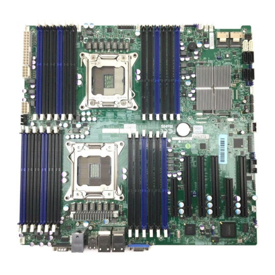
Checklist Congratulations on purchasing your computer motherboard from an acknowledged leader in the industry. Supermicro boards are designed with the utmost attention to detail to provide you with the highest standards in quality and performance. Please check that the following items have all been included with your motherboard. - Page 10 X9DR3-LN4F+/X9DRi-LN4F+ Motherboard User’s Manual Motherboard Image Note: All graphics shown in this manual were based upon the latest PCB Revision available at the time of publishing of the manual. The motherboard you've received may or may not look exactly the same as the graphics shown in this manual.
-
Page 11: Motherboard Layout
Chapter 1: Overview Motherboard Layout USB 2/3 USB 0/1 LAN2/4 LAN1/3 COM1 LEM1 IPMI_LAN CPU2 JI2C2 JI2C1 X9DR3-LN4F+/X9DRi-LN4F+ Rev. 1.10 XDP-CPU CPU1 JWP1 SAS4~7 SAS0~3 FAN1 Note: For the latest CPU/Memory updates, please refer to our website at http://www.supermicro.com/products/motherboard/ for details. - Page 12 X9DR3-LN4F+/X9DRi-LN4F+ Motherboard User’s Manual X9DR3-LN4F+/X9DRi-LN4F+ Quick Reference LAN2/4 LAN1/3 USB 2/3 USB 0/1 COM1 LEM1 IPMI_LAN CPU2 JI2C2 JI2C1 X9DR3-LN4F+/X9DRi-LN4F+ Rev. 1.10 XDP-CPU CPU1 JWP1 SAS4~7 SAS0~3 FAN1 Notes: • See Chapter 3 for detailed information on jumpers, I/O ports and JF1 front panel connections.
- Page 13 Chapter 1: Overview X9DR3-LN4F+/X9DRi-LN4F+ Jumpers Jumper Description Default Setting JBT1 Clear CMOS See Chapter 2 C1/JI SMB to PCI-E Slots Pins 2-3 (Normal) JPB1 BMC Enabled Pins 1-2 (Enabled) JPG1 VGA Enabled Pins 1-2 (Enabled) JPL1 GLAN1/GLAN2 Enable Pins 1-2 (Enabled) JPME1 Management Engine (ME) Pins 1-2 (Normal)
- Page 14 X9DR3-LN4F+/X9DRi-LN4F+ Motherboard User’s Manual JTPM1 TPM (Trusted Platform Module)/Port 80 KB/Mouse PS2 Keyboard/Mouse LAN1/3, LAN2/4 G-bit Ethernet Ports 1/3, 2/4 (IPMI) LAN IPMI_Dedicated LAN SCU 0~3, 4~7 Storage Control Unit Connectors 0~3, 4~7 (X9DR3-LN4F+) Onboard Buzzer (Internal Speaker) USB 0/1 Back Panel USB 0/1 USB 2/3 Back Panel USB 2/3...
-
Page 15: Motherboard Features
Chapter 1: Overview Motherboard Features • Dual Intel E5-2600(v2) Series Processors (Socket R ® LGA 2011); each processor supports four full-width Intel QuickPath Interconnect (QPI) links (with support of up to 25.6 GT/s per QPI link and with Data Transfer Rate of up to 8.0 GT/s per direction). - Page 16 X9DR3-LN4F+/X9DRi-LN4F+ Motherboard User’s Manual SCU Connections • SCU Ports 0~3, 4~7 (X9DR3-LN4F+ Only), 0~3 (X9DRi-LN4F+ Only) • RAID Support RAID 0, 1, 10 Integrated IPMI 2.0 • IPMI 2.0 supported by the Winbond WPCM 450R Serial (COM) Port • Two (2) Fast UART 16550 Connection: 9-pin RS- 232 port Keyboard/Mouse •...
- Page 17 SuperDoctor® III, Watch Dog, NMI • Chassis Intrusion Header and Detection • Dimensions 13.68" (L) x 13.05" (W) (347.47 mm x 331.47 mm) Note: For IPMI Configuration Instructions, please refer to the Embedded IPMI Configuration User's Guide available @ http://www.supermicro.com/ support/manuals/.
-
Page 18: System Block Diagram
X9DR3-LN4F+/X9DRi-LN4F+ Motherboard User’s Manual CPU REAR Socket 2 PROCESSOR CPU FRONT Socket 1 PROCESSOR SYSTEM BIOS SATA x4 [7.4] (4 SATA2 for X9DRi -LN4F+ Only) (For X9DR3 -LN4F+ Only) [3.0] Intel C606/C602 PEG0 PEG1 [4:1] PEG1_8 6, 7 REAR REAR BMC VGA PHY1 VGA CONN... -
Page 19: Processor And Chipset Overview
Chapter 1: Overview Processor and Chipset Overview Built upon the functionality and the capability of the Intel E5-2600(v2) Series Processors (Socket R LGA 2011) and the C606/C602 chipset, the X9DR3-LN4F+/ X9DRi-LN4F+ motherboard provides the performance and feature sets required for dual_processor-based HPC/Cluster/Database servers. (See note below for processor support.) With support of Intel QuickPath interconnect (QPI) Technology, the X9DR3-LN4F+/ X9DRi-LN4F+ offers point-to-point serial interconnect interface with a transfer... -
Page 20: Special Features
X9DR3-LN4F+/X9DRi-LN4F+ Motherboard User’s Manual Special Features Recovery from AC Power Loss The Basic I/O System (BIOS) provides a setting that determines how the system will respond when AC power is lost and then restored to the system. You can choose for the system to remain powered off (in which case you must press the power switch to turn it back on), or for it to automatically return to the power-on state. -
Page 21: Acpi Features
Chapter 1: Overview voltages and fan speeds go beyond a predefined range. ACPI Features ACPI stands for Advanced Configuration and Power Interface. The ACPI specifica- tion defines a flexible and abstract hardware interface that provides a standard way to integrate power management features throughout a PC system, including its hardware, operating system and application software. -
Page 22: Super I/O
X9DR3-LN4F+/X9DRi-LN4F+ Motherboard User’s Manual areas where noisy power transmission is present, you may choose to install a line filter to shield the computer from noise. It is recommended that you also install a power surge protector to help avoid problems caused by power surges. Super I/O The Super I/O supports two high-speed, 16550 compatible serial communication ports (UARTs). -
Page 23: Overview Of The Nuvoton Wpcm450 Controller
Chapter 1: Overview Overview of the Nuvoton WPCM450 Controller The Nuvoton WPCM450R Controller, a Baseboard Management Controller (BMC), supports 2D/VGA-compatible Graphic Cores with PCI interface, creating multi-media virtualization via Keyboard/Video/Mouse Redirection (KVMR). The WPCM450R Controller is ideal for remote system management. The WPCM450R Controller interfaces with the host system via PCI connections to communicate with the graphics cores. - Page 24 • RMCP+ protocol supported Note 1: For more information on IPMI configuration, please refer to the IPMI User's Guide posted on our website at http://www.supermicro.com/ support/manuals/. Note 2: The term "IPMI controller" and the term "BMC controller" can be used interchangeably in this section.
-
Page 25: Chapter 2 Installation
The following statements are industry-standard warnings, provided to warn the user of situations which have the potential for bodily injury. Should you have questions or experience difficulty, contact Supermicro's Technical Support department for assis- tance. Only certified technicians should attempt to install or configure components. - Page 26 X9DR3-LN4F+/X9DRi-LN4F+ Motherboard User’s Manual Attention Danger d'explosion si la pile n'est pas remplacée correctement. Ne la remplacer que par une pile de type semblable ou équivalent, recommandée par le fabricant. Jeter les piles usagées conformément aux instructions du fabricant. ¡Advertencia! Existe peligro de explosión si la batería se reemplaza de manera incorrecta.
-
Page 27: Product Disposal
Chapter 2: Installation Product Disposal Warning! Ultimate disposal of this product should be handled according to all national laws and regulations. 製品の廃棄 この製品を廃棄処分する場合、 国の関係する全ての法律 ・ 条例に従い処理する必要が あります。 警告 本产品的废弃处理应根据所有国家的法律和规章进行。 警告 本產品的廢棄處理應根據所有國家的法律和規章進行。 Warnung Die Entsorgung dieses Produkts sollte gemäß allen Bestimmungen und Gesetzen des Landes erfolgen. -
Page 28: Static-Sensitive Devices
X9DR3-LN4F+/X9DRi-LN4F+ Motherboard User’s Manual Static-Sensitive Devices Electrostatic Discharge (ESD) can damage electronic com ponents. To avoid dam- aging your system board, it is important to handle it very carefully. The following measures are generally sufficient to protect your equipment from ESD. Precautions •... -
Page 29: Processor And Heatsink Installation
CPU socket cap is in place and none of the socket pins are bent; otherwise, contact your retailer immediately. • Refer to the Supermicro website for updates on CPU support. Installing the LGA2011 Processor 1. There are two load levers on the LGA2011 socket. To open the socket cover, first press and release the load lever labeled 'Open 1st'. - Page 30 X9DR3-LN4F+/X9DRi-LN4F+ Motherboard User’s Manual 2. Press the second load lever labeled 'Close 1st' to release the load plate that covers the CPU socket from its locking position. Pull lever away from Press down on Load the the socket Lever labeled 'Close 1st' 3.
- Page 31 Chapter 2: Installation 1. Using your thumb and the index finger, remove the 'WARNING' plastic cap from the socket. 2. Use your thumb and index finger to hold the CPU on its edges. Align the CPU keys, which are semi-circle cutouts, against the socket keys. Socket Keys CPU Keys 3.
- Page 32 X9DR3-LN4F+/X9DRi-LN4F+ Motherboard User’s Manual 4. With the CPU inside the socket, inspect the four corners of the CPU to make sure that the CPU is properly installed. 5. Close the load plate with the CPU inside the socket. Lock the lever labeled 'Close 1st' first, then lock the lever labeled 'Open 1st' second.
-
Page 33: Installing A Passive Cpu Heatsink
Chapter 2: Installation Installing a Passive CPU Heatsink 1. Do not apply any thermal grease to the heatsink or the CPU die -- the re- quired amount has already been applied. 2. Place the heatsink on top of the CPU so that the four mounting holes are aligned with those on the Motherboard's and the Heatsink Bracket under- neath. -
Page 34: Removing The Heatsink
X9DR3-LN4F+/X9DRi-LN4F+ Motherboard User’s Manual Removing the Heatsink Warning: We do not recommend that the CPU or the heatsink be removed. However, if you do need to uninstall the heatsink, please follow the instructions below to uninstall the heatsink to prevent damage done to the CPU or the CPU socket. 1. -
Page 35: Installing And Removing The Memory Modules
Chapter 2: Installation Installing and Removing the Memory Modules Note: Check Supermicro's Website for recommended memory modules. CAUTION Exercise extreme care when installing or removing DIMM modules to prevent any possible damage. Installing & Removing DIMMs 1. Insert the desired number of DIMMs into the memory slots, starting with P1-DIMMA1. - Page 36 Load Reduced (LRDIMM) ECC or up to128 GB of Unbuffered (UDIMM) ECC/Non- ECC DDR3 800/1066/1333/1600/1866 MHz DDR3 4-channel memory modules (24 modules max for RDIMMs/LRDIMMs, 16 modules max. for UDIMMs) For the latest memory updates, please refer to our Website a at http://www.supermicro. com/products/motherboard. Processor & Memory Module Population Configuration For memory to work properly, follow the tables below for memory installation.
- Page 37 1333 1333 Note: For detailed information on memory support and updates, please refer to the SMC Recommended Memory List posted on our website at http://www.supermicro.com/support/ resources/mem.cfm. Populating RDIMM (ECC) Memory Modules Intel E5-2600(v2) Series Processor RDIMM Memory Support-Table Ranks Per...
- Page 38 1066 1333 Note: For detailed information on memory support and updates, please refer to the SMC Recom- mended Memory List posted on our website at http://www.supermicro.com/support/resources/ mem.cfm. Other Important Notes and Restrictions • For the memory modules to work properly, please install DIMM modules of the same type, same speed and same operating frequency on the motherboard.
-
Page 39: Motherboard Installation
Chapter 2: Installation Motherboard Installation All motherboards have standard mounting holes to fit different types of chassis. Make sure that the locations of all the mounting holes for both motherboard and chassis match. Although a chassis may have both plastic and metal mounting fas- teners, metal ones are highly recommended because they ground the motherboard to the chassis. -
Page 40: Installing The Motherboard
X9DR3-LN4F+/X9DRi-LN4F+ Motherboard User’s Manual Installing the Motherboard 1. Install the I/O shield into the chassis. 2. Locate the mounting holes on the motherboard. 3. Locate the matching mounting holes on the chassis. Align the mounting holes on the motherboard against the mounting holes on the chassis. 4. -
Page 41: Control Panel Connectors And I/O Ports
Chapter 2: Installation Control Panel Connectors and I/O Ports The I/O ports are color coded in conformance with the PC 99 specification. See the picture below for the colors and locations of the various I/O ports. Back Panel Connectors and I/O Ports LAN2/4 LAN1/3 USB 2/3... -
Page 42: Serial Ports
X9DR3-LN4F+/X9DRi-LN4F+ Motherboard User’s Manual Serial Ports Serial COM) Ports Pin Definitions Two COM connections (COM1 & Pin # Definition Pin # Definition COM2) are located on the motherboard. COM1 is located on the Backplane I/O panel. COM2, located close to CPU1 Slot1 PCI-E slot, provides front access support. -
Page 43: Universal Serial Bus (Usb)
Chapter 2: Installation Universal Serial Bus (USB) Backplane USB (USB 0/1, 2/3) Four Universal Serial Bus ports Pin Definitions (USB 0/1, USB 2/3) are located on Pin# Definition the I/O back panel. In addition, two USB headers, located close to the Intel PCH chip, provides four front- accessible USB connections (USB Ground... -
Page 44: Ethernet Ports
X9DR3-LN4F+/X9DRi-LN4F+ Motherboard User’s Manual Ethernet Ports LAN Ports Pin Definition Four Gigabit Ethernet ports (LAN1/3, Pin# Definition LAN2/4) are located on the I/O back- P2V5SB SGND plane on the motherboard. In addition, TD0+ Act LED an IPMI_Dedicated LAN is located TD0- P3V3SB above USB 0/1 ports on the back- TD1+... -
Page 45: Unit Identifier Switch
Chapter 2: Installation Unit Identifier Switch UID Switch A Unit Identifier (UID) Switch and two LED Pin# Definition Indicators are located on the motherboard. Ground The UID Switch is located next to the LAN Ground 2/4 ports on the backplane. The Rear UID Button In LED (LE2) is located next to the UID Switch. -
Page 46: Front Control Panel
These connectors are designed specifically for use with Supermicro's server chassis. See the figure below for the descriptions of the various control panel buttons and LED indicators. Refer to the following section for descriptions and pin definitions. -
Page 47: Front Control Panel Pin Definitions
Chapter 2: Installation Front Control Panel Pin Definitions NMI Button NMI Button Pin Definitions (JF1) The non-maskable interrupt button Pin# Definition header is located on pins 19 and 20 Control of JF1. Refer to the table on the right Ground for pin definitions. Power LED Power LED Pin Definitions (JF1) The Power LED connection is located Pin#... -
Page 48: Hdd Led
X9DR3-LN4F+/X9DRi-LN4F+ Motherboard User’s Manual HDD LED HDD LED Pin Definitions (JF1) The HDD LED connection is located Pin# Definition on pins 13 and 14 of JF1. Attach a 3.3V Standby cable here to indicate HDD activ- HD Active ity. See the table on the right for pin definitions. -
Page 49: Overheat (Oh)/Fan Fail/Pwr Fail/Uid Led
Chapter 2: Installation Overheat (OH)/Fan Fail/PWR Fail/ OH/Fan Fail/ PWR Fail/Blue_UID UID LED LED Pin Definitions (JF1) Pin# Definition Connect an LED cable to pins 7 and Red_LED-Cathode/OH/Fan Fail/ 8 of Front Control Panel to use the Power Fail5.5V.SB Overheat/Fan Fail/Power Fail and Blue_UID LED UID LED connections. -
Page 50: Reset Button
X9DR3-LN4F+/X9DRi-LN4F+ Motherboard User’s Manual Reset Button Reset Button Pin Definitions (JF1) The Reset Button connection is located Pin# Definition on pins 3 and 4 of JF1. Attach it to a Reset hardware reset switch on the computer Ground case. Refer to the table on the right for pin definitions. -
Page 51: Connecting Cables
Chapter 2: Installation Connecting Cables ATX Power 24-pin Connector Pin Definitions Pin# Definition Pin # Definition Power Connectors +3.3V +3.3V -12V +3.3V A 24-pin main power supply connector(JPW1) and two 8-pin CPU PWR connectors PS_ON (JPW2/3) are located on the motherboard. These power connectors meet the SSI EPS 12V specification. -
Page 52: Fan Headers
X9DR3-LN4F+/X9DRi-LN4F+ Motherboard User’s Manual Fan Headers Fan Header Pin Definitions This motherboard has eight system/CPU Pin# Definition fan headers (Fan 1~Fan 6, Fan A, Fan Ground B) on the motherboard. All these 4-pin +12V fans headers are backward compatible Tachometer with the traditional 3-pin fans. However, Firmware Thermal fan speed control is available for 4-pin Management... -
Page 53: Internal Speaker
Chapter 2: Installation Internal Speaker Internal Buzzer (SP1) Pin Definition The Internal Speaker, located at SP1, Pin# Definitions can be used to provide audible indica- Pin 1 Pos. (+) Beep In tions for various beep codes. See the Pin 2 Neg. (-) Alarm table on the right for pin definitions. -
Page 54: Tpm Header/Port 80
X9DR3-LN4F+/X9DRi-LN4F+ Motherboard User’s Manual TPM Header/Port 80 TPM/Port 80 Header Pin Definitions A Trusted Platform Module/Port 80 Pin # Definition Pin # Definition header is located at JTPM1 to provide LCLK TPM support and Port 80 connection. LFRAME# <(KEY)> Use this header to enhance system LRESET# +5V (X) performance and data security. -
Page 55: Power Smb (I 2 C) Connector
Chapter 2: Installation Power SMB (I C) Connector PWR SMB Pin Definitions Power System Management Bus (I Pin# Definition Connector (JPI C1) monitors power Clock supply, fan and system temperatures. Data See the table on the right for pin PWR Fail definitions. -
Page 56: T-Sgpio 1/2 Headers
X9DR3-LN4F+/X9DRi-LN4F+ Motherboard User’s Manual T-SGPIO 1/2 Headers T-SGPIO Pin Definitions Two SGPIO (Serial-Link General Pin# Definition Definition Purpose Input/Output) headers are lo- cated at J17/J18 on the motherboard. Ground Data These headers support Serial_Link Load Ground interface for onboard SATA connec- Clock tions. -
Page 57: Ipmb
Chapter 2: Installation IPMB IPMB Header Pin Definitions A System Management Bus header for Pin# Definition IPMI 2.0 is located at IPMB. Connect the Data appropriate cable here to use the IPMB Ground C connection on your system. Clock No Connection LAN2/4 LAN1/3 USB 2/3... -
Page 58: Jumper Settings
X9DR3-LN4F+/X9DRi-LN4F+ Motherboard User’s Manual Jumper Settings Explanation of Jumpers Connector Pins To modify the operation of the mother- board, jumpers can be used to choose between optional settings. Jumpers cre- Jumper ate shorts between two pins to change the function of the connector. Pin 1 is identified with a square solder pad Setting on the printed circuit board. -
Page 59: Cmos Clear
Chapter 2: Installation CMOS Clear JBT1 is used to clear CMOS. Instead of pins, this "jumper" consists of contact pads to prevent accidental clearing of CMOS. To clear CMOS, use a metal object such as a small screwdriver to touch both pads at the same time to short the connection. Always remove the AC power cord from the system before clearing CMOS. -
Page 60: Vga Enable
X9DR3-LN4F+/X9DRi-LN4F+ Motherboard User’s Manual VGA Enable VGA Enable Jumper Settings Jumper JPG1 allows the user to en- Jumper Setting Definition able the onboard VGA connectors. The Enabled (Default) default setting is 1-2 to enable the con- Disabled nection. See the table on the right for jumper settings. -
Page 61: Management Engine (Me) Recovery
Chapter 2: Installation Management Engine (ME) Recovery Management Engine (ME) Recovery ME Recovery Jumper Settings Use Jumper JPME1 to select ME Firm- Use Jumper JPME1 to select ME Firm- Jumper Setting Definition ware Recovery mode, which will limit ware Recovery mode, which will limit Normal (Default) resource allocation for essential system resource allocation for essential system... -
Page 62: Onboard Led Indicators
X9DR3-LN4F+/X9DRi-LN4F+ Motherboard User’s Manual Onboard LED Indicators GLAN LEDs Link LED The Gigabit LAN ports are located on the Activity LED Rear View (when facing the IO Backplane on the motherboard. Each rear side of the chassis) Ethernet LAN port has two LEDs. The Yel- GLAN Activity Indicator (Left) low LED indicates activity. -
Page 63: Onboard Power Led
Chapter 2: Installation Onboard Power LED Onboard PWR LED Indicator (LE1) LED Settings An Onboard Power LED is located at LE1 LED Color Status on the motherboard. When this LED is on, System Off (PWR cable not connected) the system is on. Be sure to turn off the Green System On system and unplug the power cord before... -
Page 64: Bmc Heartbeat Led
X9DR3-LN4F+/X9DRi-LN4F+ Motherboard User’s Manual BMC Heartbeat LED BMC Heartbeat LED Status A BMC Heartbeat LED is located at LEM1 Color/State Definition on the motherboard. When LEM1 is blink- Green: BMC: Normal ing, BMC functions normally. See the Blinking table at right for more information. A. -
Page 65: 2-10 Serial Ata Connections
Intel PCH chip. See the table on the right for pin definitions. Note: For more information on SATA HostRAID configuration, please refer to the Intel SATA HostRAID User's Guide posted on our Website @ http:// www.supermicro.com. A. I-SATA0 LAN2/4 LAN1/3... - Page 66 X9DR3-LN4F+/X9DRi-LN4F+ Motherboard User’s Manual Notes 2-42...
-
Page 67: Chapter 3 Troubleshooting
Chapter 3: Troubleshooting Chapter 3 Troubleshooting Troubleshooting Procedures Use the following procedures to troubleshoot your system. If you have followed all of the procedures below and still need assistance, refer to the ‘Technical Support Procedures’ and/or ‘Returning Merchandise for Service’ section(s) in this chapter. Warning: Always disconnect the power cord before adding, changing or installing any hardware components. -
Page 68: System Boot Failure
X9DR3-LN4F+/X9DRi-LN4F+ Motherboard User’s Manual No Video 1. If the power is on, but you have no video, remove all add-on cards and cables. 2. Use the speaker to determine if any beep codes exist. Refer to Appendix A for details on beep codes. System Boot Failure If the system does not display POST or does not respond after the power is turned on, check the following:... -
Page 69: Memory Errors
2. Memory support: Make sure that the memory modules are supported by test- ing the modules using memtest86 or a similar utility. Note: Refer to the product page on our website at http://www.supermicro. com for memory and CPU support and updates. - Page 70 X9DR3-LN4F+/X9DRi-LN4F+ Motherboard User’s Manual to make sure that the CPU and System temperatures are within the normal range. Also check the front panel Overheat LED, and make sure that the Overheat LED is not on. 5. Adequate power supply: Make sure that the power supply provides adequate power to the system.
-
Page 71: Technical Support Procedures
Technical Support Procedures Before contacting Technical Support, please take the following steps. Also, please note that as a motherboard manufacturer, Supermicro also sells motherboards through its channels, so it is best to first check with your distributor or reseller for troubleshooting services. -
Page 72: Battery Removal And Installation
X9DR3-LN4F+/X9DRi-LN4F+ Motherboard User’s Manual Battery Removal and Installation Battery Removal To remove the onboard battery, follow the steps below: 1. Power off your system and unplug your power cable. 2. Locate the onboard battery. 3. Using a tool such as a pen or a small screwdriver, push the battery lock out- wards to unlock it. -
Page 73: Frequently Asked Questions
Note : The SPI BIOS chip used on this motherboard cannot be removed. Send your motherboard back to our RMA Department at Supermicro for repair. For BIOS Recovery instructions, please refer to the AMI BIOS Recovery Instructions posted at http://www.supermicro.com. -
Page 74: Returning Merchandise For Service
Shipping and handling charges will be applied for all orders that must be mailed when service is complete. For faster service, You can also request a RMA authorization online (http://www.supermicro.com/RmaForm/). This warranty only covers normal consumer use and does not cover damages in- curred in shipping or from failure due to the alternation, misuse, abuse or improper maintenance of products. -
Page 75: Chapter 4 Bios
Chapter 4: AMI BIOS Chapter 4 BIOS Introduction This chapter describes the AMI BIOS setup utility for the X9DR3-LN4F+/X9DRi- LN4F+. It also provides the instructions on how to navigate the AMI BIOS setup utility screens. The AMI ROM BIOS is stored in a Flash EEPROM and can be easily updated. -
Page 76: Main Setup
X9DR3-LN4F+/X9DRi-LN4F+ Motherboard User’s Manual Note: For AMI UEFI BIOS Recovery, please refer to the UEFI BIOS Re- covery User Guide posted @http://www.supermicro.com/support/manuals/. Starting the Setup Utility Normally, the only visible Power-On Self-Test (POST) routine is the memory test. As the memory is being tested, press the <F2> key to enter the main menu of the AMI BIOS setup utility. -
Page 77: 4-3 Advanced Setup Configurations
Chapter 4: AMI BIOS System Time This item displays the system time in HH:MM:SS format (e.g. 15:32:52). Supermicro X9DRi-LN4+/X9DR3-LN4+ Version This item displays the SMC version of the BIOS ROM used in this system. Build Date This item displays the date that the BIOS setup utility was built. - Page 78 X9DR3-LN4F+/X9DRi-LN4F+ Motherboard User’s Manual AddOn ROM Display Mode Use this item to set the display mode for the Option ROM. Select Keep Current to use the current AddOn ROM Display setting. Select Force BIOS to use the Option ROM display mode set by the system BIOS. The options are Force BIOS and Keep Current.
- Page 79 Chapter 4: AMI BIOS power to be turned on after a power loss. Select Last State to allow the system to resume its last state before a power loss. The options are Power-On, Power-Off and Last State. CPU Configuration This submenu displays the information of the CPU as detected by the BIOS. It also allows the user to configuration CPU settings.
- Page 80 X9DR3-LN4F+/X9DRi-LN4F+ Motherboard User’s Manual 64-bit This item indicates if the CPU installed in Socket 1 or Socket 2 supports 64-bit technology. Clock Spread Spectrum Select Enable to enable Clock Spectrum support, which will allow the BIOS to moni- tor and attempt to reduce the level of Electromagnetic Interference caused by the components whenever needed.
- Page 81 Chapter 4: AMI BIOS MLC Spatial Prefetcher (Available when supported by the CPU) If set to Enabled, the MLC (Mid-Level Cache) Spatial prefetcher will prefetch the both cache lines for 128 bytes as comprised. If set to Disabled, the MLC (Mid-Level Cache) Spatial prefetcher will prefetch the adjacent cache line for 64 bytes.
- Page 82 X9DR3-LN4F+/X9DRi-LN4F+ Motherboard User’s Manual Turbo Mode (Available when Power Technology is set to Custom) Select Enabled to use the Turbo Mode to boost system performance. The options are Enabled and Disabled. C1E (Available when Power Technology is set to Custom) Select Enabled to enable Enhanced C1 Power State to boost system per- formance.
-
Page 83: North Bridge
Chapter 4: AMI BIOS Long Duration Power Limit This item displays the power limit set by the manufacturer during which long duration power is maintained. Factory Long Duration Maintained (Available when Power Technology is set to Custom) This item displays the period of time set by the manufacturer during which long duration power is maintained. - Page 84 X9DR3-LN4F+/X9DRi-LN4F+ Motherboard User’s Manual Intel I/OAT The Intel I/OAT (I/O Acceleration Technology) significantly reduces CPU over- head by leveraging CPU architectural improvements, freeing the system resource for other tasks. The options are Disabled and Enabled. DCA Support Select Enabled to use Intel's DCA (Direct Cache Access) Technology to improve data transfer efficiency.
- Page 85 Chapter 4: AMI BIOS CPU2 Slot5 PCI-E 3.0 x 16 Link Speed This feature allows the user to set the PCI-Exp bus speed for the slot specified above. The options are Gen1 (Generation 1), Gen2 and Gen3. CPU2 Slot4 PCI-E 3.0 x 16 Link Speed This feature allows the user to set the PCI-Exp bus speed for the slot specified above.
- Page 86 X9DR3-LN4F+/X9DRi-LN4F+ Motherboard User’s Manual Sparing This item displays if memory sparing is supported by the motherboard. Memory sparing enhances system performance. DIMM Information CPU Socket 1 DIMM Information P1-DIMMA1~3, P1-DIMMB1~3, P1-DIMMC1~3, P1-DIMMD1~3 CPU Socket 2 DIMM Information P1-DIMME1~3, P1-DIMMF1~3, P1-DIMMG1~3, P1-DIMMH1~3 The status of the memory modules specified above will be displayed as detected by the BIOS.
- Page 87 Chapter 4: AMI BIOS (the original source). When this item is set to Enabled, the IO hub will read and write back one cache line every 16K cycles, if there is no delay caused by internal processing. By using this method, roughly 64 GB of memory behind the IO hub will be scrubbed every day.
- Page 88 X9DR3-LN4F+/X9DRi-LN4F+ Motherboard User’s Manual All USB Devices This feature enables all USB ports/devices. The options are Disabled and Enabled. (If set to Enabled, EHCI Controller 1 and Controller 2 will appear.) EHCI Controller 1/EHCI Controller 2 (Available when All USB Devices is set to Enabled) Select Enabled to enable EHCI (Enhanced Host Controller Interface) Controller 1 or Controller 2.
- Page 89 Chapter 4: AMI BIOS IDE Mode The following items are displayed when IDE Mode is selected: SATA (Serial-ATA) Controller 0~1 Use this feature to activate or deactivate the SATA controller, and set the compatibility mode. The options for Controller 0 are Enhanced and Com- patible.
- Page 90 X9DR3-LN4F+/X9DRi-LN4F+ Motherboard User’s Manual SCU RAID Option ROM/UEFI Driver Select Enabled to support the onboard SCU Option ROM to boot up the system via a storage device. The options are Disabled and Enabled. SCU Port 0~SCU Port 7: The AMI BIOS will automatically detect the onboard SCU devices and display the status of each SCU device as detected.
- Page 91 Chapter 4: AMI BIOS to allow the system BIOS to automatically set the ASPM level for the system. Select Disabled to disable ASPM support. The options are Disabled, Force L0, and Auto. Warning: Enabling ASPM support may cause some PCI-E devices to fail! Above 4G Decoding (Available if the system supports 64-bit PCI decoding) Select Enabled to decode a PCI device that supports 64-bit in the space above 4G Address.
- Page 92 X9DR3-LN4F+/X9DRi-LN4F+ Motherboard User’s Manual Super IO Configuration Super IO Chip: This item displays the Super IO chip used in the motherboard. Serial Port 1 Configuration Serial Port Select Enabled to enable a serial port specified by the user. The options are En- abled and Disabled. Device Settings This item displays the IP address and IRQ (Interrupt Request) address of Serial Port 1.
-
Page 93: Serial Port Console Redirection
Chapter 4: AMI BIOS Serial Port 2 Attribute Use this feature to select the attribute for serial port 2. The options are SOL (Serial On LAN), and High Speed. Serial Port Console Redirection • COM 1/COM 2 These two submenus allow the user to configure the following Console Redirection settings for a COM Port specified by the user. - Page 94 X9DR3-LN4F+/X9DRi-LN4F+ Motherboard User’s Manual in transmission. Select Mark to add a mark as a parity bit to be sent along with the data bits. Select Space to add a Space as a parity bit to be sent with your data bits. The options are None, Even, Odd, Mark and Space. Stop Bits A stop bit indicates the end of a serial data packet.
-
Page 95: Console Redirection Settings (For Ems)
Chapter 4: AMI BIOS Console Redirection Settings (for EMS) Use this feature to specify how the host computer will exchange data with the client computer, which is the remote computer used by the user. Out-of-Band Management Port The feature selects a serial port used by the Microsoft Windows Emergency Management Services (EMS) to communicate with a remote server. - Page 96 X9DR3-LN4F+/X9DRi-LN4F+ Motherboard User’s Manual Trusted Computing (Available when a TPM device is detected by the BIOS) Configuration TPM Support Select Enabled on this item and enable the TPM jumper on the motherboard to enable TPM support to improve data integrity and network security. The options are Enabled and Disabled.
-
Page 97: Acpi Setting
Chapter 4: AMI BIOS TPM Owner Status This item displays the status of TPM Ownership. ACPI Setting Use this feature to configure Advanced Configuration and Power Interface (ACPI) power management settings for your system. ACPI Sleep State Use this feature to select the ACPI State when the system is in sleep mode. Select S1 (CPU_Stop_Clock) to erase all CPU caches and stop executing instructions. -
Page 98: Event Logs
X9DR3-LN4F+/X9DRi-LN4F+ Motherboard User’s Manual Event Logs Use this feature to configure Event Log settings. Change SMBIOS Event Log Settings This feature allows the user to configure SMBIOS Event settings. Enabling/Disabling Options SMBIOS Event Log Select Enabled to enable SMBIOS (System Management BIOS) Event Logging during system boot. - Page 99 Chapter 4: AMI BIOS Erasing Settings Erase Event Log Select Enabled to erase the SMBIOS (System Management BIOS) Event Log, which is completed before a event logging is initialized upon system reboot. The options are No and Yes. When Log is Full Select Erase Immediately to immediately erase SMBIOS error event logs that ex- ceed the limit when the SMBIOS event log is full.
-
Page 100: Ipmi
X9DR3-LN4F+/X9DRi-LN4F+ Motherboard User’s Manual IPMI Use this feature to configure Intelligent Platform Management Interface (IPMI) settings. IPMI Firmware Revision This item indicates the IPMI firmware revision used in your system. IPMI Status This item indicates the status of the IPMI firmware installed in your system. System Event Log ... - Page 101 Chapter 4: AMI BIOS When SEL is Full This feature allows the user to decide what the BIOS should do when the system event log is full. Select Erase Immediately to erase all events in the log when the system event log is full. The options are Do Nothing and Erase Immediately. Customize EFI Logging Options Log EFI Status Codes Select Enabled to log EFI (Extensible Firmware Interface) Status Codes, Error...
-
Page 102: Boot
X9DR3-LN4F+/X9DRi-LN4F+ Motherboard User’s Manual Station MAC Address This item displays the Station MAC address for this computer. Mac addresses are 6 two-digit hexadecimal numbers. Gateway IP Address This item displays the Gateway IP address for this computer. This should be in decimal and in dotted quad form (i.e., 192.168.10.253). - Page 103 Chapter 4: AMI BIOS Delete Boot Option Use this feature to select a boot device to delete from the boot priority list. Delete Boot Option Select the desired boot device to delete. Network Device BBS Priorities This item is used to select the boot device priority sequence from available network devices.
-
Page 104: Security
X9DR3-LN4F+/X9DRi-LN4F+ Motherboard User’s Manual Security This menu allows the user to configure the following security settings for the system. Password Check Use this feature to determine when a password entry is required. Select Setup for the system to request a password upon entering the AMI BIOS setup utility. Select Always to require the password when entering setup and upon each system boot. -
Page 105: Save & Exit
Chapter 4: AMI BIOS Save & Exit This submenu allows the user to configure the Save and Exit settings for the system. Discard Changes and Exit Select this option to exit the BIOS Setup without making any permanent changes to the system configuration, and reboot the computer. Select Discard Changes and Exit, and press <Enter>. - Page 106 X9DR3-LN4F+/X9DRi-LN4F+ Motherboard User’s Manual Discard Changes Select this feature and press <Enter> to discard all the changes and return to the BIOS setup. When the dialog box appears, asking you if you want to load previ- ous values, click Yes to load the values previous saved, or click No to keep the changes you've made so far.
-
Page 107: Appendix A Bios Error Beep Codes
Appendix A: BIOS POST Error Codes Appendix A BIOS Error Beep Codes During the POST (Power-On Self-Test) routines, which are performed at each system boot, errors may occur. Non-fatal errors are those which, in most cases, allow the system to continue to boot. - Page 108 X9DR3-LN4F+/X9DRi-LN4F+ Motherboard User’s Manual Notes...
-
Page 109: Appendix B Software Installation Instructions
Appendix B Software Installation Instructions B-1 Installing Software Programs The Supermicro ftp site contains drivers and utilities for your system at ftp://ftp. supermicro.com. Some of these must be installed, such as the chipset driver. After accessing the ftp site, go into the CDR_Images directory and locate the ISO file for your motherboard. -
Page 110: Configuring Superdoctor Iii
X9DR3-LN4F+/X9DRi-LN4F+ Motherboard User’s Manual Note 2: When making a storage driver diskette by booting into a Driver CD, please set the SATA Configuration to "Compatible Mode" and configure SATA as IDE in the BIOS Setup. After making the driver diskette, be sure to change the SATA settings back to your original settings. - Page 111 SuperDoctor® III Interface Display Screen-II (Remote Control) Note: SD III Software Revision 1.0 can be downloaded from our Web Site at: ftp://ftp.supermicro.com/utility/Super_Doctor_III/. You can also download the SDIII User's Guide at: <http://www.supermicro.com/PROD- UCT/Manuals/SDIII/UserGuide.pdf>. For Linux, we will recommend using SuperDoctor II.
- Page 112 X9DR3-LN4F+/X9DRi-LN4F+ Motherboard User’s Manual Notes...
- Page 113 (Disclaimer Continued) The products sold by Supermicro are not intended for and will not be used in life support systems, medical equipment, nuclear facilities or systems, aircraft, aircraft devices, aircraft/emergency communication devices or other critical systems whose failure to perform be reasonably expected to result in significant injury or loss of life or catastrophic property damage.
Need help?
Do you have a question about the Supero X9DRi-LN4F+ and is the answer not in the manual?
Questions and answers