Table of Contents

Related Manuals for Supermicro X11SRA


Summary of Contents for Supermicro X11SRA
- Page 1 X11SRA X11SRA-F X11SRA-RF USER MANUAL Revision 1.0a...
- Page 2 State of California, USA. The State of California, County of Santa Clara shall be the exclusive venue for the resolution of any such disputes. Supermicro's total liability for all claims will not exceed the price paid for the hardware product.
-
Page 3: About This Manual
About This Manual This manual is written for system integrators, IT technicians, and knowledgeable end users. It provides information for the installation and use of the X11SRA/-F/-RF motherboard. About This Motherboard The Supermicro X11SRA and X11SRA-F/-RF motherboards support a single Intel® Xeon®... -
Page 4: Contacting Supermicro
Super X11SRA/-F/-RF User's Manual Contacting Supermicro Headquarters Address: Super Micro Computer, Inc. 980 Rock Ave. San Jose, CA 95131 U.S.A. Tel: +1 (408) 503-8000 Fax: +1 (408) 503-8008 Email: marketing@supermicro.com (General Information) support@supermicro.com (Technical Support) Website: www.supermicro.com Europe Address: Super Micro Computer B.V. -
Page 5: Table Of Contents
Table of Contents Table of Contents Preface Chapter 1 Introduction 1.1 Checklist ..........................8 Quick Reference .......................11 Quick Reference Table ......................12 Motherboard Features .......................14 1.2 Processor and Chipset Overview ..................18 1.3 Special Features ........................18 Recovery from AC Power Loss ..................18 1.4 System Health Monitoring ....................19 Onboard Voltage Monitors ....................19 Fan Status Monitor with Firmware Control ...............19 Environmental Temperature Control .................19... - Page 6 Super X11SRA/-F/-RF User's Manual DIMM Module Population Sequence ................31 DIMM Installation ......................32 DIMM Removal .........................32 2.5 Rear I/O Ports ........................33 2.6 Front Control Panel ......................37 2.7 Connectors .........................42 Power Connections ......................42 Headers ..........................44 2.8 Jumper Settings .........................53 How Jumpers Work ......................53 2.9 LED Indicators ........................57...
- Page 7 Table of Contents 4.6 Security ..........................93 4.7 Boot ............................96 4.8 Save & Exit .........................98 Appendix A BIOS Codes Appendix B Software Installation B.1 Installing Software Programs ...................101 Appendix C Standardized Warning Statements Battery Handling ......................103 Product Disposal ......................105 Appendix D UEFI BIOS Recovery D.1 Overview ...........................106 D.2 Recovering the UEFI BIOS Image ...................106 D.3 Recovering the Main BIOS Block with a USB Device .............107...
-
Page 8: Chapter 1 Introduction
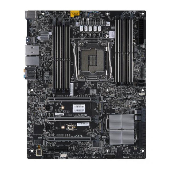
Introduction Congratulations on purchasing your computer motherboard from an industry leader. Supermicro motherboards are designed to provide you with the highest standards in quality and performance. In addition to the motherboard, several important parts that are included with the motherboard are listed below. - Page 9 Chapter 1: Introduction Figure 1-1. X11SRA Motherboard Image Note: All graphics shown in this manual were based upon the latest PCB revision available at the time of publication of the manual. The motherboard you received may or may not look exactly the same as the graphics shown in this manual.
- Page 10 Super X11SRA/-F/-RF User's Manual Figure 1-2. X11SRA Motherboard Layout (not drawn to scale) AUDIO_FP1 USB 6/7(3.0) HD AUDIO KB/MOUSE LAN1 LAN2 USB 0/1 USB 8/9(3.0) USB 12/13(3.1) LEDBMC MH12 JNVI2C1 FAN4 MH10 DIMMB1 DIMMB2 MH13 MH11 DIMMA1 DIMMA2 BAR CODE LGA 2066 CPU M.2 PCI-E 3.0 x4...
-
Page 11: Quick Reference
Chapter 1: Introduction Quick Reference AUDIO_FP1 LAN1 CPU SLOT6 M.2 PCI-E 3.0 x16 LEDBMC USB 12/13(3.1) LAN2 CPU SLOT2 M.2 PCI-E 3.0 x8 (INx16) USB6/7 (3.0) USB 8/9(3.0) MH12 KB/MOUSE COM1 HD AUDIO USB 0/1 CPU SLOT4 M.2 PCI-E 3.0 x16 AUDIO_FP1 USB 6/7(3.0) HD AUDIO... -
Page 12: Quick Reference Table
Chassis Intrusion Header JNVME1 NVMe Connector (supports two connections) JNVI2C1 NVMe I2C Header JPI2C1 Power I2C System Management Bus (Power SMB) Header (for X11SRA-F/-RF only) JPWR1 +12V 8-pin CPU Power Connector (Required) JPWR2 24-pin ATX Main Power Connector (Required) JRK1... - Page 13 Chapter 1: Introduction Connector Description Internal Speaker/Buzzer USB 0/1 Back Panel USB 2.0 Ports USB 2/3, USB 4/5 Front Accessible USB 2.0 Headers USB 6/7, USB 8/9 Back Panel USB 3.0 Ports USB 10/11 Front Accessible USB 3.0 Header (Type A) USB 12/13 Back Panel USB 3.1 Ports Back Panel VGA Port...
-
Page 14: Motherboard Features
Motherboard Features Motherboard Features • The X11SRA and X11SRA-F/-RF motherboards support a single Intel Xeon W-21xx series processor in an LGA2066 socket Memory • Supports up to 256GB of RDIMM or 512GB of LRDIMM ECC/Non-ECC DDR4 memory, two DIMMs per channel (DPC) - Page 15 CPU/System overheat control • CPU Thermal Trip support Fan Control • Fan status monitoring with firmware 4-pin fan speed control via IPMI or SIO (X11SRA) interface • Multi-speed fan control via onboard BMC System Management • PECI (Platform Environment Control Interface) 3.1 support •...
- Page 16 Note 2: For IPMI configuration instructions, please refer to the Embedded IPMI Con- figuration User's Guide available at http://www.supermicro.com/support/manuals/. Note 3: If you purchase a Supermicro Out of Band (OOB) software license key (Supermicro P/N: SFT-OOB-LIC), please DO NOT change the IPMI MAC address.
- Page 17 Chapter 1: Introduction Figure 1-3. Chipset Block Diagram Intel Voltage monitor FAN SPEED CTRL Temp Sensor RT1/ RT2 NCT6792D-B COM Header Note: This is a general block diagram and may not exactly represent the features on your motherboard. Refer to the previous pages for the actual specifications of your motherboard.
-
Page 18: Processor And Chipset Overview
The X11SRA and X11SRA-F/-RF motherboards support a single Intel Xeon W-21xx series processor in the LGA2066 socket. With the Intel C422 PCH, the X11SRA/-F/-RF is a high- end, multi-GPU workstation motherboard that offers reliablity and stability. It offers the latest high-performance features such as NVMe, M.2/U.2 storage interfaces, and DDR4 memory... -
Page 19: System Health Monitoring
Chapter 1: Introduction 1.4 System Health Monitoring The motherboard has an onboard Baseboard Management Controller (BMC) chip that supports system health monitoring. Onboard Voltage Monitors The onboard voltage monitor will continuously scan crucial voltage levels. Once a voltage becomes unstable, it will give a warning or send an error message to the screen. Users can adjust the voltage thresholds to define the sensitivity of the voltage monitor. -
Page 20: Power Supply
As with all computer products, a stable power source is necessary for proper and reliable operation. It is even more important for processors that have high CPU clock rates. The X11SRA/-F/-RF motherboard accommodates a 24-pin ATX power supply. Although most power supplies generally meet the specifications required by the CPU, some are inadequate. -
Page 21: Chapter 2 Installation
Chapter 2: Installation Chapter 2 Installation 2.1 Static-Sensitive Devices Electrostatic Discharge (ESD) can damage electronic com ponents. To prevent damage to your motherboard, it is important to handle it very carefully. The following measures are generally sufficient to protect your equipment from ESD. Precautions •... -
Page 22: Motherboard Installation
Super X11SRA/-F/-RF User's Manual 2.2 Motherboard Installation All motherboards have standard mounting holes to fit different types of chassis. Make sure that the locations of all the mounting holes for both the motherboard and the chassis match. Although a chassis may have both plastic and metal mounting fasteners, metal ones are highly recommended because they ground the motherboard to the chassis. -
Page 23: Installing The Motherboard
Chapter 2: Installation Installing the Motherboard 1. Locate the mounting holes on the motherboard. Refer to the previous page for the location. 2. Locate the matching mounting holes on the chassis. Align the mounting holes on the motherboard against the mounting holes on the chassis. 3. -
Page 24: Processor And Heatsink Installation
CPU socket cap is in place and none of the socket pins are bent; otherwise, contact your retailer immediately. • Refer to the Supermicro website for updates on CPU support. Installing a CPU 1. There are two load levers on the LGA2066 socket. To open the socket cover, press and release the load lever labeled "Open 1st". - Page 25 Chapter 2: Installation 2. Press the second load lever labeled "Close 1st" to release the load plate that covers the CPU socket from its locking position. Press down on Load Pull lever away from Lever 'Close 1st' the socket 3. With the "Close 1st" lever fully retracted, gently push down on the "Open 1st" lever to open the load plate.
- Page 26 Super X11SRA/-F/-RF User's Manual 5. Use your thumb and index finger to hold the CPU on its edges. Align the CPU keys, which are semi-circle cutouts, against the socket keys. Socket Keys CPU Keys 6. Once they are aligned, carefully lower the CPU straight down into the socket. To avoid damaging the CPU or socket, do not drop the CPU onto the socket, move it horizontally or vertically, or rub it against the socket pins.
- Page 27 Chapter 2: Installation 8. Close the load plate with the CPU inside the socket. Lock the "Close 1st" lever first, then lock the "Open 1st" lever second. Gently push the load levers down to the lever locks. Push down and lock Gently close the 'Close 1st' lever.
-
Page 28: Installing A Cpu Heatsink
Super X11SRA/-F/-RF User's Manual Installing a CPU Heatsink 1. Apply the proper amount of thermal grease to the heatsink. 2. Place the heatsink on top of the CPU so that the two mounting holes on the heatsink are aligned with those on the retention mechanism. Tighten the screws in the following... -
Page 29: Removing A Heatsink
Chapter 2: Installation Removing a Heatsink Warning: We do not recommend that the CPU or the heatsink be removed. However, if you do need to remove the heatsink, please follow the instructions below to uninstall the heatsink to avoid damaging the CPU or other components. 1. -
Page 30: Memory Support And Installation
Memory Support The X11SRA/-F/-RF motherboard supports up to 256GB of RDIMM or 512GB of LRDIMM ECC/Non-ECC DDR4 memory with speeds of up to 2666MHz in eight memory slots. Populating these DIMM slots with memory modules of the same type and size will result in interleaved memory, which will improve memory performance. -
Page 31: Dimm Module Population Sequence
Chapter 2: Installation DIMM Module Population Sequence When installing memory modules, the DIMM slots should be populated in the following order: DIMMA1, DIMMB1, DIMMC1, DIMMD1, then DIMMA2, DIMMB2, DIMMC2, DIMMD2. • Always use DDR4 DIMM modules of the same type, size, and speed. •... -
Page 32: Dimm Installation
Super X11SRA/-F/-RF User's Manual DIMM Installation AUDIO_FP1 USB 6/7(3.0) 1. Insert the desired number of DIMMs into HD AUDIO KB/MOUSE LAN2 LAN1 USB 0/1 USB 8/9(3.0) USB 12/13(3.1) LEDBMC MH12 JNVI2C1 FAN4 MH10 the memory slots, starting with DIMMA1, DIMMB1... -
Page 33: Rear I/O Ports
Chapter 2: Installation 2.5 Rear I/O Ports Refer to Figure 2-1 below for the locations and descriptions of the various I/O ports on the rear of the motherboard. AUDIO_FP1 USB 6/7(3.0) HD AUDIO KB/MOUSE LAN2 LAN1 USB 0/1 USB 8/9(3.0) USB 12/13(3.1) LEDBMC JNVI2C1... - Page 34 Super X11SRA/-F/-RF User's Manual VGA Port A VGA video port is located next to USB0/1 on the I/O back panel. Refer to the motherboard layout below for the location. High Definition Audio This motherboard features a 7.1+2 Channel High Definition Audio (HDA) codec that provides 10 DAC channels.
- Page 35 Chapter 2: Installation Universal Serial Bus (USB) Ports This motherboard supports a total of eight USB ports located on the I/O back panel and three USB headers for front access. The USB ports on the I/O back panel are two USB 2.0 ports (USB 0/1), four USB 3.0 ports (USB 6/7, 8/9), and two USB 3.1 ports (USB 12/13).
-
Page 36: Lan Ports
Super X11SRA/-F/-RF User's Manual LAN Ports The motherboard has one 5GbE and one 1GbE RJ45 port (LAN1/LAN2) on the I/O back panel. These ports accept RJ45 cables. Please refer to Section 2.9 for LAN LED information. LAN1/LAN2 Port Pin Definitions... -
Page 37: Front Control Panel
JF1 contains header pins for various buttons and indicators that are normally located on a control panel at the front of the chassis. These connectors are designed specifically for use with Supermicro chassis. Refer to the figure below for the descriptions of the front control panel buttons and LED indicators. -
Page 38: Power Button
Super X11SRA/-F/-RF User's Manual Power Button The Power Button connection is located on pins 1 and 2 of JF1. Momentarily contacting both pins will power on/off the system. This button can also be configured to function as a suspend button (with a setting in the BIOS - refer to Chapter 4). To turn off the power when the system is in the suspend mode, press the button for four seconds or longer. -
Page 39: Power Fail Led
Chapter 2: Installation Power Fail LED The Power Fail LED connection is located on pins 5 and 6 of JF1. Refer to the table below for pin definitions. Power Fail LED Pin Definitions (JF1) Pins Definition 3.3V Power Fail Overheat (OH)/Fan Fail LED Connect an LED cable to pins 7 and 8 of the Front Control Panel to use the Overheat/Fan Fail LED connections. - Page 40 Super X11SRA/-F/-RF User's Manual NIC1/NIC2 (LAN1/LAN2) LED The NIC (Network Interface Controller) LED connection for LAN port 1 is located on pins 11 and 12 of JF1, and the LED connection for LAN port 2 is on pins 9 and 10. Attach the NIC LED cables here to display network activity.
-
Page 41: Power Led
Chapter 2: Installation Power LED The Power LED connection is located on pins 15 and 16 of JF1. Refer to the table below for pin definitions. Power LED Pin Definitions (JF1) Pin# Definition 3.3V PWR LED NMI Button The non-maskable interrupt button header is located on pins 19 and 20 of JF1. Refer to the table below for pin definitions. -
Page 42: Connectors
Super X11SRA/-F/-RF User's Manual 2.7 Connectors Power Connections Main ATX Power Supply Connectors The primary power supply connector (JPWR2) meets the ATX SSI EPS 12V specification. You must also connect the 8-pin (JPWR1) processor power connector to your power supply. -
Page 43: Pin Power Connector
Chapter 2: Installation 8-Pin Power Connector The +12V 8-pin Power Connector located at JPWR1 must also be connected to the power supply. This connector is used to power the processor. +12V 8-pin Power Connector Pin Definitions Pin# Definition 1 - 4 Ground 5 - 8 +12V... -
Page 44: Headers
Headers Fan Headers The X11SRA/-F/-RF has five fan headers (FAN1 ~ FAN4, FANA). All of these 4-pin fan headers are backwards-compatible with the traditional 3-pin fan headers. However, fan speed control is available for 4-pin fan headers only by Thermal Management via the IPMI 2.0 interface. -
Page 45: Chassis Intrusion Header
Chapter 2: Installation Chassis Intrusion Header A Chassis Intrusion header is located at JL1 on the motherboard. Attach the appropriate cable from the chassis to inform you of a chassis intrusion when the chassis is opened. Refer to the table below for pin definitions. Chassis Intrusion Header Pin Definitions Pin#... - Page 46 Super X11SRA/-F/-RF User's Manual SGPIO Headers Two I-SGPIO (Serial Link General Purpose Input/Output) headers are located on the motherboard. They support the onboard I-SATA 3.0 ports. Refer to the tables below for pin definitions. I-SGPIO1/I-SGPIO2 Header I-SGPIO1/I-SGPIO2 Header Pin Definitions...
-
Page 47: Standby Power Header
Chapter 2: Installation Standby Power Header The +5V Standby Power header is located at JSTBY1 on the motherboard. You must have a card with a Standby Power connector and a cable to use this feature. Refer to the table below for pin definitions. Standby Power Header Pin Definitions Pin#... -
Page 48: Front Accessible Audio Header
Super X11SRA/-F/-RF User's Manual Intel RAID Key Header The JRK1 header allows the user to enable RAID functions. Refer to the table below for pin definitions. Intel RAID Key Header Pin Definitions Pins Definition PU 3.3V PCH RAID KEY Front Accessible Audio Header A 10-pin audio header (AUDIO_FP1) allows you to use the onboard sound for audio playback. - Page 49 Chapter 2: Installation TPM/Port 80 Header A Trusted Platform Module (TPM)/Port 80 header is located at JTPM1 to provide TPM support and a Port 80 connection. Use this header to enhance system performance and data security. Refer to the table below for pin definitions. Trusted Platform Module Header Pin Definitions Pin#...
- Page 50 Super X11SRA/-F/-RF User's Manual 4-pin External BMC I C Header A System Management Bus header for IPMI 2.0 is located at JIPMB1. Connect the appropriate cable here to use the IPMB I C connection on your system. Refer to the table below for pin definitions.
- Page 51 Six SATA 3.0 connectors, supported by the Intel C422 PCH chipset, are located on the X11SRA/-F/-RF motherboard. These SATA ports support RAID 0, 1, 5, and 10. SATA ports provide serial-link signal connections, which are faster than the connections of Parallel ATA.
- Page 52 Super X11SRA/-F/-RF User's Manual NVMe Connector JNVME1 is a Non-volatile Memory Express (NVMe) connector that provides two connections for high speed PCI-E storage devices. The NVMe interface provides lower data latency for increased efficiency and performance. 1. JNVME1 AUDIO_FP1 USB 6/7(3.0)
-
Page 53: Jumper Settings
Chapter 2: Installation 2.8 Jumper Settings How Jumpers Work To modify the operation of the motherboard, jumpers can be used to choose between optional settings. Jumpers create shorts between two pins to change the function of the connector. Pin 1 is identified with a square solder pad on the printed circuit board. Refer to the diagram below for an example of jumping pins 1 and 2. - Page 54 Super X11SRA/-F/-RF User's Manual CMOS Clear JBT1 is used to clear the CMOS. Instead of pins, this jumper consists of contact pads to prevent accidental clearing of the CMOS. To clear the CMOS, use a metal object such as a small screwdriver to touch both pads at the same time to short the connection.
- Page 55 Chapter 2: Installation Manufacturing Mode Close pins 2-3 of JPME2 to bypass SPI flash security and force the system to operate in the manufacturing mode, which will allow the user to flash the system firmware from a host server for system setting modifications. Refer to the table below for jumper settings. Manufacturing Mode Jumper Settings Jumper Setting...
- Page 56 Super X11SRA/-F/-RF User's Manual Audio Enable/Disable Use JPAC1 to enable or disable the onboard audio support. Refer to the table below for jumper settings. Audio Enable/Disable Jumper Settings Jumper Setting Definition Pins 1-2 Enabled (Default) Pins 2-3 Disabled 1. Audio Enable/Disable AUDIO_FP1 USB 6/7(3.0)
-
Page 57: Led Indicators
Chapter 2: Installation 2.9 LED Indicators LAN LEDs Two LAN ports (LAN1/LAN2) are located on the I/O back panel of the motherboard. Each Ethernet LAN port has two LEDs. The green LED indicates activity, while the other Link LED may be green, amber, or off to indicate the speed of the connection. Refer to the tables below for more information. - Page 58 Super X11SRA/-F/-RF User's Manual Power LED The Onboard Power LED is located at LEDPWR on the motherboard. When this LED is on, the system is on. Turn off the system and unplug the power cord before removing or installing any component. Refer to the table below for more information.
- Page 59 Chapter 2: Installation M.2 LEDs There are two M.2 LEDs (LE1/LE2) on the motherboard. LE1 is next to the M.2 slot at J12 and LE2 is next to the M.2 slot at J13. When the LED is blinking, the M.2 device is working. M.2 LEDs LED Color Definition...
-
Page 60: Chapter 3 Troubleshooting
Super X11SRA/-F/-RF User's Manual Chapter 3 Troubleshooting 3.1 Troubleshooting Procedures Use the following procedures to troubleshoot your system. If you have followed all of the procedures below and still need assistance, refer to the ‘Technical Support Procedures’ and/ or ‘Returning Merchandise for Service’ section(s) in this chapter. Always disconnect the AC power cord before adding, changing or installing any non hot-swap hardware components. -
Page 61: System Boot Failure
1. Make sure that the memory modules are compatible with the system and that the DIMMs are properly and fully installed. (For memory compatibility, refer to the memory compatibility chart posted on our website at http://www.supermicro.com.) 2. Check if different speeds of DIMMs have been installed. It is strongly recommended that you use the same RAM type and speed for all DIMMs in the system. -
Page 62: Losing The System's Setup Configuration
Super X11SRA/-F/-RF User's Manual Losing the System's Setup Configuration 1. Make sure that you are using a high-quality power supply. A poor-quality power supply may cause the system to lose the CMOS setup information. Refer to Section 2.7 for details on recommended power supplies. - Page 63 Chapter 3: Troubleshooting 3. Using the minimum configuration for troubleshooting: Remove all unnecessary components (starting with add-on cards first), and use the minimum configuration (but with the CPU and a memory module installed) to identify the trouble areas. Refer to the steps listed in Section A above for proper troubleshooting procedures.
-
Page 64: Technical Support Procedures
Before contacting Technical Support, please take the following steps. Also, please note that as a motherboard manufacturer, Supermicro also sells motherboards through its channels, so it is best to first check with your distributor or reseller for troubleshooting services. They should know of any possible problems with the specific system configuration that was sold to you. -
Page 65: Frequently Asked Questions
Note: The SPI BIOS chip used on this motherboard cannot be removed. Send your motherboard back to our RMA Department at Supermicro for repair. For BIOS Recov- ery instructions, please refer to the AMI BIOS Recovery Instructions posted at http:// www.supermicro.com/support/manuals/. -
Page 66: Battery Removal And Installation
Super X11SRA/-F/-RF User's Manual 3.4 Battery Removal and Installation Battery Removal To remove the onboard battery, follow the steps below: 1. Power off your system and unplug your power cable. 2. Locate the onboard battery as shown below. 3. Using a tool such as a pen or a small screwdriver, push the battery lock outwards to unlock it. -
Page 67: Returning Merchandise For Service
Shipping and handling charges will be applied for all orders that must be mailed when service is complete. For faster service, RMA authorizations may be requested online (http://www.supermicro.com/ support/rma/). This warranty only covers normal consumer use and does not cover damages incurred in shipping or from failure due to the alteration, misuse, abuse, or improper maintenance of products. -
Page 68: Chapter 4 Bios
BIOS 4.1 Introduction This chapter describes the AMIBIOS™ Setup utility for the X11SRA-F motherboard. The BIOS is stored on a chip and can be easily upgraded using a flash program. Note: Due to periodic changes to the BIOS, some settings may have been added or deleted and might not yet be recorded in this manual. -
Page 69: Main Setup
Note: The time is in the 24-hour format. For example, 5:30 P.M. appears as 17:30:00. The date's default value is 03/02/2017 after RTC reset. Supermicro X11SRA-RF BIOS Version This feature displays the version of the BIOS ROM used in the system. -
Page 70: Advanced Setup Configurations
Super X11SRA/-F/-RF User Manual 4.3 Advanced Setup Configurations Use the arrow keys to select Boot Setup and press <Enter> to access the submenu features. Warning: Take caution when changing the Advanced settings. An incorrect value, a very high DRAM frequency, or an incorrect DRAM timing setting may make the system unstable. -
Page 71: Cpu Configuration
Chapter 4: BIOS Manageability Features State This feature allows the user to enable and disable Manageability Features support in FW. To disable support platform, the system must be in an unprovisioned state first. The options are Enabled and Disabled. AMT BIOS Features This feature allows the user to enable and disable AMT BIOS feature. - Page 72 Super X11SRA/-F/-RF User Manual Execute Disable Bit Set to Enabled for Execute Disable Bit support which will allow the processor to designate areas in the system memory where an application code can execute and where it cannot, thus preventing a worm or a virus from flooding illegal codes to overwhelm the processor or damaging the system during a virus attack.
-
Page 73: Advanced Power Management Configuration
Chapter 4: BIOS LLC Prefetcher If this feature is set to Enable, LLC (hardware cache) prefetching on all threads will be supported. The options are Disable and Enable. DCU Mode Set the data-prefecting mode for the DCU (Data Cache Unit). The options are 32KB 8way without ECC and 16KB 4 way with ECC. -
Page 74: Chipset Configuration
Super X11SRA/-F/-RF User Manual Hardware PM (Power Management) State Control Hardware P-States If this feature is set to Disable, hardware will choose a P-State setting for the system based on an OS request. If this feature is set to Native Mode, hardware will choose a P- State setting based on OS guidance. -
Page 75: North Bridge
Chapter 4: BIOS North Bridge This feature allows the user to configure the settings for the Intel North Bridge. Memory Configuration Integrated Memory Controller (iMC) Enforce POR Select POR to enforce POR restrictions for DDR4 memory frequency and voltage pro- gramming. -
Page 76: Iio Configuration
Super X11SRA/-F/-RF User Manual Mirror Mode Select Enable to set all 1LM/2LM memory installed in the system on the mirror mode, which will create a duplicate copy of data stored in the memory to increase memory security, but it will reduce the memory capacity into half. The options are Mirror Mode 1LM, Mirror Mode 2LM, and Disable. - Page 77 Chapter 4: BIOS CPU1 Configuration IOU0 (Slot4) This feature configures the PCI-E Bifuraction setting for a PCI-E port specified by the user. The options are x4x4x4x4, x4x4x8, x8x4x4, x8x8, x16, and Auto. IOU1 (Slot6) This feature configures the PCI-E Bifuraction setting for a PCI-E port specified by the user.
- Page 78 Super X11SRA/-F/-RF User Manual Relaxed Ordering Select Enable to enable Relaxed Ordering support which will allow certain transactions to violate the strict-ordering rules of PCI and to be completed prior to other transactions that have already been enqueued. The options are Disable and Enable.
-
Page 79: South Bridge
Chapter 4: BIOS VMD Config for PStack2 Intel® VMD for Volume Management Select Enable to use the Intel Volume Management Device Technology for this stack. The options are Disable and Enable. PCI-E Completion Timeout Disable Select Enable to enable PCI-E Completion Timeout support for electric tuning. The options are Yes, No, and Per-Port. -
Page 80: Acpi Settings
Super X11SRA/-F/-RF User Manual Configure SATA as Use this feature to select the mode for the installed SATA drives. The options are AHCI and RAID. Select AHCI to configure a SATA drive specified by the user as an AHCI drive. Select RAID to configure a SATA drive specified by the user as a RAID drive. -
Page 81: Boot Feature
Chapter 4: BIOS WHEA Support Select Enabled to support the Windows Hardware Error Architecture (WHEA) platform and provide a common infrastructure for the system to handle hardware errors within the Windows OS environment to reduce system crashes and to enhance system recovery and health monitoring. - Page 82 Super X11SRA/-F/-RF User Manual INT19 (Interrupt 19) Trap Response Interrupt 19 is the software interrupt that handles the boot disk function. When this feature is set to Immediate, the ROM BIOS of the host adaptors will "capture" Interrupt 19 at boot up immediately and allow the drives that are attached to these host adaptors to function as bootable disks.
-
Page 83: Serial Port 1 Configuration
Chapter 4: BIOS NCT6792D Super IO Configuration NCT6792D Super IO Configuration Super IO Chip - NCT6792D Serial Port 1 Configuration Serial Port 1 This feature enables the Serial Port 1 (COM1). The options are Unchecked and Checked. Current Limit Override - The current limit override is shown. Device Setting - IO=3F8h;... -
Page 84: Serial Port Console Redirection
Super X11SRA/-F/-RF User Manual Serial Port Console Redirection COM1 COM1 Console Redirection Select Enabled to enable console redirection support for a serial port specified by the user. The options are Disabled and Enabled. *If COM1 Console Redirection is set to Enabled, the following features will become available for user's configuration: Console Redirection Settings... - Page 85 Chapter 4: BIOS Flow Control Use this feature to set the flow control for Console Redirection to prevent data loss caused by buffer overflow. Send a "Stop" signal to stop sending data when the receiving buffer is full. Send a "Start" signal to start sending data when the receiving buffer is empty. The options are None and Hardware RTS/CTS.
- Page 86 Super X11SRA/-F/-RF User Manual MMCFG Size This feature determines the lowest MMCFG (Memory-Mapped Configuration) base assigned to PCI devices. The options are 64M, 128M, 256M. 512M, 1G, and 2G. MMIOHBase Use this feature to select the base memory size according to memory-address mapping for the I/O hub.
- Page 87 Chapter 4: BIOS Onboard LAN1 Option ROM Onboard LAN2 Option ROM Use the features above to select the type of the device installed in a LAN port specified by the user for system boot. The default setting for Onboard LAN1 Option ROM is PXE and the default setting for Onboard LAN2 Option ROM is Disabled.
-
Page 88: Event Logs
Super X11SRA/-F/-RF User Manual 4.4 Event Logs Use this feature to configure Event Logs settings. Change SMBIOS Event Log Settings Enabling/Disabling Options SMBIOS Event Log Change this feature to enable or disable all features of the SMBIOS Event Logging during system boot. -
Page 89: View Smbios Event Log
Chapter 4: BIOS SMBIOS Event Log Standard Settings Log System Boot Event This feature toggles the System Boot Event logging to enable or disable. The options are Enabled and Disabled. MECI The Multiple Event Count Increment (MECI) counter counts the number of occurences that a duplicate event must happen before the MECI counter is incremented. -
Page 90: Ipmi
Super X11SRA/-F/-RF User Manual 4.5 IPMI Use this feature to configure Intelligent Platform Management Interface (IPMI) settings. BMC Firmware Revision This feature indicates the IPMI firmware revision used in your system. IPMI Status This feature indicates the status of the IPMI firmware installed in your system. -
Page 91: Bmc Network Configuration
Chapter 4: BIOS Custom EFI Logging Options Log EFI Status Codes This feature allows the user to disable the logging of EFI Status Codes, enable Error code, enable Progress code, and enable both codes. The options are Disabled, Both, Error code, and Progress Code. - Page 92 Super X11SRA/-F/-RF User Manual Gateway IP Address This feature displays the Gateway IP address for this computer. This should be in decimal and in dotted quad form (i.e., 172.31.0.1). VLAN Use this feature to enable or disable the IPMI VLAN function. The options are Disable and Enable.
-
Page 93: Security
Chapter 4: BIOS 4.6 Security Use this submenu to create Administrator and User passwords. Using ONLY an Administrator password limits access to BIOS setup. Using ONLY a User password will lock unauthorized users from booting the system and/or entering BIOS setup. Administrator Password Press Enter to create a new, or change an existing Administrator password. - Page 94 Super X11SRA/-F/-RF User Manual CSM Support Select Enabled to support the EFI Compatibility Support Module (CSM), which provides compatibility support for traditional legacy BIOS for system boot. The options are Disabled and Enabled. *If Secure Boot Mode is set to Custom, the following features will become available for user's configuration: Reset to Setup Mode...
-
Page 95: Authorized Signatures
Chapter 4: BIOS Append Key Select Yes to add the KEK from the manufacturer's defaults list to the existing KEK. Select No to load the KEK from a file. The options are Yes and No. Authorized Signatures Set New Key Select Yes to load the database from the manufacturer's defaults. -
Page 96: Boot
Super X11SRA/-F/-RF User Manual 4.7 Boot Use this feature to configure Boot Settings: Boot Configuration Boot Configuration Setup Prompt Timeout Enter the wait time in seconds to wait for the setup activation key. Enter 65535 for indefinite wait time. The default is 1. - Page 97 Chapter 4: BIOS Delete Driver Option NETWORK Drive BBS Priorities This feature allows the user to specify which UEFI network drive devices are boot devices. Boot Option #1 Save Changes and Reset This feature resets the system after saving changes. ...
-
Page 98: Save & Exit
Super X11SRA/-F/-RF User Manual 4.8 Save & Exit Select the Exit tab from the BIOS setup utility screen to enter the Exit BIOS Setup screen. Save Options Discard Changes and Exit Use this feature to quit the BIOS Setup without making any permanent changes to the system configuration, and reboot the computer. - Page 99 Chapter 4: BIOS Default Options Restore Defaults To set this feature, select Restore Optimized Defaults from the Save & Exit menu and press <Enter>. These are factory settings designed for maximum system stability, but not for maximum performance. Save As User Defaults To set this feature, select Save as User Defaults from the Exit menu and press <Enter>.
-
Page 100: Appendix A Bios Codes
Super X11SRA/-F/-RF User Manual Appendix A BIOS Codes BIOS Error POST (Beep) Codes During the POST (Power-On Self-Test) routines, which are performed upon each system boot, errors may occur. Non-fatal errors are those which, in most cases, allow the system to continue to boot. These error messages normally appear on the screen. -
Page 101: Appendix B Software Installation
Appendix B Software Installation B.1 Installing Software Programs The Supermicro website that contains drivers and utilities for your system is located at https:// www.supermicro.com/wftp/driver/. Some of these must be installed, such as the chipset driver. After accessing the product drivers and utilities page, go into the CDR_Images directory and locate the ISO file for your motherboard. - Page 102 BIOS setup. After making the driver diskette, be sure to change the SATA settings back to your original settings.B.2 SuperDoctor® 5 The Supermicro SuperDoctor 5 is a hardware monitoring program that functions in a command-line or web-based interface in Windows and Linux operating systems. The program...
-
Page 103: Appendix C Standardized Warning Statements
The following statements are industry standard warnings, provided to warn the user of situations which have the potential for bodily injury. Should you have questions or experience difficulty, contact Supermicro's Technical Support department for assistance. Only certified technicians should attempt to install or configure components. - Page 104 Super X11SRA/-F/-RF User's Manual Attention Danger d'explosion si la pile n'est pas remplacée correctement. Ne la remplacer que par une pile de type semblable ou équivalent, recommandée par le fabricant. Jeter les piles usagées conformément aux instructions du fabricant. ¡Advertencia! Existe peligro de explosión si la batería se reemplaza de manera incorrecta.
-
Page 105: Product Disposal
Appendix C: Warning Statements Product Disposal Warning! Ultimate disposal of this product should be handled according to all na- tional laws and regulations. 製品の廃棄 この製品を廃棄処分する場合、 国の関係する全ての法律 ・ 条例に従い処理する必要があります。 警告 本产品的废弃处理应根据所有国家的法律和规章进行。 警告 本產品的廢棄處理應根據所有國家的法律和規章進行。 Warnung Die Entsorgung dieses Produkts sollte gemäß allen Bestimmungen und Gesetzen des Landes erfolgen. -
Page 106: Appendix D Uefi Bios Recovery
Warning: Do not upgrade the BIOS unless your system has a BIOS-related issue. Flashing the wrong BIOS can cause irreparable damage to the system. In no event shall Supermicro be liable for direct, indirect, special, incidental, or consequential damages arising from a BIOS update. -
Page 107: Recovering The Main Bios Block With A Usb Device
USB device or a writable CD/DVD. Note 1: If you cannot locate the "Super.ROM" file in your drive disk, visit our website www.supermicro.com to download the BIOS package. Extract the BIOS binary image into a USB flash device and rename it "Super.ROM" for the BIOS recovery use. - Page 108 Super X11SRA/-F/-RF User's Manual 3. After locating the healthy BIOS binary image, the system will enter the BIOS Recovery menu as shown below. Note: At this point, you may decide if you want to start the BIOS recovery. If you decide to proceed with BIOS recovery, follow the procedures below.
- Page 109 Appendix D: UEFI BIOS Recovery 5. After the BIOS recovery process is complete, press any key to reboot the system. 6. Using a different system, extract the BIOS package into a USB flash drive. 7. Press <Del> during system boot to enter the BIOS Setup utility. From the top of the tool bar, select Boot to enter the submenu.
- Page 110 Super X11SRA/-F/-RF User's Manual 8. When the UEFI Shell prompt appears, type fs# to change the device directory path. Go to the directory that contains the BIOS package you extracted earlier from Step 6. Enter flash.nsh BIOSname.### at the prompt to start the BIOS update process.
Need help?
Do you have a question about the X11SRA and is the answer not in the manual?
Questions and answers