Table of Contents
Advertisement
Advertisement
Table of Contents

Related Manuals for Supermicro X10DRH-C


Summary of Contents for Supermicro X10DRH-C
- Page 1 X10DRH-C X10DRH-CT X10DRH-i X10DRH-iT USER’S MANUAL Revision 1.1...
- Page 2 This product, including software and docu- mentation, is the property of Supermicro and/or its licensors and is supplied only under a license. Any use or reproduction of this product is not allowed, except as expressly permitted by the terms of said license.
-
Page 3: About This Motherboard
Technology, delivering system performance, power efficiency, and feature sets to address the needs of next-generation computer users. With the PCH C612 built in, the X10DRH-C/CT/i/iT motherboard supports Intel® Node Manager 3.0, Intel MCTP Protocol, and Management Engine (ME). This motherboard is ideal for general purpose, storage appliance, and head node server platforms. -
Page 4: Conventions Used In The Manual
X10DRH-C/CT/i/iT Motherboard User’s Manual Conventions Used in the Manual Pay special attention to the following symbols for proper system installation: Warning: Important information given to ensure proper system installation or to prevent damage to the components or injury to yourself;... -
Page 5: Contacting Supermicro
Super Micro Computer, Inc. 980 Rock Ave. San Jose, CA 95131 U.S.A. Tel: +1 (408) 503-8000 Fax: +1 (408) 503-8008 Email: marketing@supermicro.com (General Information) support@supermicro.com (Technical Support) Website: www.supermicro.com Europe Address: Super Micro Computer B.V. Het Sterrenbeeld 28, 5215 ML... -
Page 6: Table Of Contents
System Health Monitoring ................1-12 ACPI Features ....................1-13 Power Supply ....................1-13 Advanced Power Management ..............1-14 Intel Intelligent Power Node Manager (NM) (Available when the Supermicro ® Power Manager [SPM] is installed)............... 1-14 Management Engine (ME) ................1-14 Chapter 2 Installation Standardized Warning Statements .............. - Page 7 SAS Enable (X10DRH-C/CT only) ............2-38 2-10 Onboard LED Indicators ................2-39 GLAN LEDs ....................2-39 IPMI-Dedicated LAN LEDs ............... 2-39 Onboard Power LED ................2-40 BMC Heartbeat LED ................2-40 SAS Activity LED (For X10DRH-C/CT) ............ 2-41 SAS Fault LED (For X10DRH-C/CT) ............2-41...
- Page 8 X10DRH-C/CT/i/iT Motherboard User’s Manual SAS Heartbeat LED (For X10DRH-C/CT) ..........2-42 2-11 SATA/SAS Connections ................2-43 SATA 3.0 and S-SATA 3.0 Connections ........... 2-43 SAS Ports (X10DRH-C/CT Only) ............. 2-44 Chapter 3 Troubleshooting Troubleshooting Procedures ................3-1 Technical Support Procedures ................ 3-5 Battery Removal and Installation ..............
-
Page 9: Chapter 1 Overview
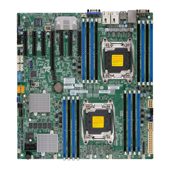
Checklist Congratulations on purchasing your computer motherboard from an acknowledged leader in the industry. Supermicro boards are designed with the utmost care and at- tention to detail to provide you with the highest standards in quality and performance. Please check that the following items have all been included with your motherboard. - Page 10 X10DRH-C/CT/i/iT Motherboard User’s Manual Motherboard Image Note: All graphics shown in this manual were based upon the latest PCB revision available at the time of publication of the manual. The mother- board you received may or may not look exactly the same as the graphics...
-
Page 11: Motherboard Layout
LEDS5 JBT1 OPEN 1st LSI 3108 SAS4-7 SAS0-3 SAS CTRL JS39 FANA JSTBY1 JOH1 Differences between X10DRH-C/X10DRH-CT/X10DRH-i/X10DRH-iT X10DRH-C X10DRH-CT X10DRH-i X10DRH-iT SAS Connections (0-3, 4-7) LSI SAS Controller CacheVault support for the onboard 3108 controller 10G-LAN (TLAN) (w/X540 LAN Controller) - Page 12 X10DRH-C/CT/i/iT Motherboard User’s Manual X10DRH-C/CT/i/iT Quick Reference LAN2 LAN1 USB0/1 COM1 FAN6 USB4/5 LAN CTRL (3.0) FAN5 CPU2 CLOSE 1st JIPMB1 OPEN 1st BAR CODE MAC CODE Battery X10DRH-C/i(T) BIOS Rev. 1.00 BIOS LICENSE CPU1 CLOSE 1st LEDS6 LEDS5 JBT1...
- Page 13 IPMI_dedicated LAN support by the ASpeed controller I-SATA 0-5 SATA 3.0 connectors supported by Intel PCH (I-SATA 0-5), (I- SATA4/I-SATA5: can be used as Supermicro SuperDOM (Disk- on-Module) with built-in power connectors) S-SATA SATA 3.0 vertical connector w/4-SATA connections supported...
- Page 14 X10DRH-C/CT/i/iT Motherboard User’s Manual (CPU2)Slot4 PCI-Express 3.0 x16 slot from CPU2 (CPU2)Slot5 PCI-Express 3.0 x8 slot from CPU2 (CPU2)Slot6 PCI-Express 3.0 x8 slot from CPU2 (CPU2)Slot7 PCI-Express 3.0 x8 slot from CPU2 (I-)SGPIO1/2 Seria_Link General Purpose I/O headers 1/2 for SATA ports (I-...
-
Page 15: Motherboard Features
Graphics Graphics controller via ASpeed 2400 BMC • Network Intel® i350 Gigabit (10/100/1000 Mb/s) Ethernet Con- troller for LAN 1/LAN 2 ports (X10DRH-C/i) • Intel® X540 10-Gigabit (T) Ethernet Controller for LAN 1/LAN 2 ports (X10DRH-CT/iT) • ASpeed AST 2400 Baseboard Controller (BMC) sup- ports IPMI 2.0... -
Page 16: Peripheral Devices
• Power-on mode for AC power recovery • Intel® Intelligent Power Node Manager 3.0 (avail- able when the Supermicro Power Manager [SPM] is installed and a special power supply is used. See the note on Page 1-14.) • Management Engine (ME) - Page 17 CPU TDP sizing. Note 2: For IPMI configuration instructions, please refer to the Embedded IPMI Configuration User's Guide available at http://www.supermicro.com/ support/manuals/. Note 3: It is strongly recommended that you change BMC log-in informa- tion upon initial system power-on.
-
Page 18: System Block Diagram
X10DRH-C/CT/i/iT Motherboard User’s Manual X10DRH-C/i (T) #1-8 #2-8 #1-7 VCCP1 12v #2-7 #1-6 VR12.5 VR12.5 #2-6 #1-5 5 PHASE 5 PHASE #2-5 145W 145W #1-4 #2-4 #1-3 #2-3 #1-2 #2-2 #1-1 #2-1 9.6G CPU1 CPU2 9.6G 3108 PVCCIO PCI-E X8 G3 PCI-E X16 G3 (1.05/0.95) -
Page 19: Processor And Chipset Overview
Processor and Chipset Overview Built upon the functionality and capability of the Intel E5-2600 v3 Series processors (Socket R3) and the Intel C612 PCH, the X10DRH-C/CT/i/iT motherboard provides system performance, power efficiency, and feature sets to address the needs of next-generation computer users. -
Page 20: Special Features
X10DRH-C/CT/i/iT Motherboard User’s Manual Special Features Recovery from AC Power Loss The Basic I/O System (BIOS) provides a setting that determines how the system will respond when AC power is lost and then restored to the system. You can choose for the system to remain powered off (in which case you must press the power switch to turn it back on) or for it to automatically return to the power-on state. -
Page 21: Acpi Features
This is even more important for processors that have high CPU clock rates. The X10DRH-C/CT/i/iT motherboard accommodates 24-pin ATX power supplies. Although most power supplies generally meet the specifications required by the CPU, some are inadequate. In addition, two 12V 8-pin power connections are also required to ensure adequate power supply to the system. -
Page 22: Advanced Power Management
Intel Intelligent Power Node Manager (NM) (Available ® when the Supermicro Power Manager [SPM] is installed) The Intel Intelligent Power Node Manager 3.0 (IPNM) provides your system with ® real-time thermal control and power management for maximum energy efficiency. -
Page 23: Chapter 2 Installation
The following statements are industry-standard warnings, provided to warn the user of situations which have the potential for bodily injury. Should you have questions or experience difficulty, contact Supermicro's Technical Support Department for assis- tance. Only certified technicians should attempt to install or configure components. - Page 24 X10DRH-C/CT/i/iT Motherboard User’s Manual Attention Danger d'explosion si la pile n'est pas remplacée correctement. Ne la remplacer que par une pile de type semblable ou équivalent, recommandée par le fabricant. Jeter les piles usagées conformément aux instructions du fabricant. ¡Advertencia! Existe peligro de explosión si la batería se reemplaza de manera incorrecta.
-
Page 25: Product Disposal
Chapter 2: Installation Product Disposal Warning! Ultimate disposal of this product should be handled according to all national laws and regulations. 製品の廃棄 この製品を廃棄処分する場合、 国の関係する全ての法律 ・ 条例に従い処理する必要が あります。 警告 本产品的废弃处理应根据所有国家的法律和规章进行。 警告 本產品的廢棄處理應根據所有國家的法律和規章進行。 Warnung Die Entsorgung dieses Produkts sollte gemäß allen Bestimmungen und Gesetzen des Landes erfolgen. -
Page 26: Static-Sensitive Devices
X10DRH-C/CT/i/iT Motherboard User’s Manual القىانين واللىائح الىطنية جميع وفقا ل ينبغي التعامل معه هذا المنتج من التخلص النهائي عند 경고! 이 제품은 해당 국가의 관련 법규 및 규정에 따라 폐기되어야 합니다. Waarschuwing De uiteindelijke verwijdering van dit product dient te geschieden in overeenstemming met alle nationale wetten en reglementen. -
Page 27: Motherboard Installation
Location of Mounting Holes There are nine (9) mounting holes on this motherboard as indicated by the arrows. BAR CODE MAC CODE X10DRH-C/i(T) Rev. 1.00 BIOS LICENSE Caution: 1) To avoid damaging the motherboard and its components, do not use a force greater than 8 lb/inch on each mounting screw during motherboard installation. -
Page 28: Installing The Motherboard
X10DRH-C/CT/i/iT Motherboard User’s Manual Installing the Motherboard Note: Always connect the power cord last, and always remove it before adding, removing, or changing any hardware components. 1. Install the I/O shield into the chassis. 2. Locate the mounting holes on the motherboard. -
Page 29: Processor And Heatsink Installation
CPU socket cap is in place and that none of the socket pins are bent; otherwise, contact your retailer immediately. Refer to the Supermicro website for updates on CPU support. Installing the LGA2011 Processor 1. There are two load levers on the LGA2011 socket. To open the socket cover, first press and release the load lever labeled "Open 1st."... - Page 30 X10DRH-C/CT/i/iT Motherboard User’s Manual 2. Press the second load lever labeled "Close 1st" to release the load plate that covers the CPU socket from its locking position. Press down on load Pull lever away from lever "Close 1st" socket 3. With the lever labeled "Close 1st" fully retracted, gently push down on the lever labeled "Open 1st"...
- Page 31 Chapter 2: Installation 4. Use your thumb and index finger to loosen the lever and open the load plate. 5. Using your thumb and index finger, hold the CPU by its edges. Align the CPU keys, which are semicircle notches, against the socket keys. Socket Keys CPU Keys 6.
- Page 32 X10DRH-C/CT/i/iT Motherboard User’s Manual 7. With the CPU inside the socket, inspect the four corners of the CPU to make sure that the CPU is properly installed. Gently close Push down and lock the the load plate lever labeled "Close 1st"...
-
Page 33: Installing A Passive Cpu Heatsink
Chapter 2: Installation Installing a Passive CPU Heatsink 1. Do not apply any thermal grease to the heatsink or the CPU die -- the re- quired amount has already been applied. 2. Place the heatsink on top of the CPU so that the four mounting holes are aligned with those on the motherboard and the heatsink bracket underneath. -
Page 34: Removing The Cpu And The Heatsink
X10DRH-C/CT/i/iT Motherboard User’s Manual Removing the CPU and the Heatsink Warning: We do not recommend that the CPU or the heatsink be removed. However, if you do need to uninstall the CPU or the heatsink, please follow the instructions below to uninstall the heatsink to avoid damaging the CPU or the motherboard. -
Page 35: Installing And Removing The Memory Modules
Chapter 2: Installation Installing and Removing the Memory Modules Note: Check Supermicro's website for a list of recommended memory modules. CAUTION Exercise extreme care when installing or removing DIMM modules to avoid damaging the DIMM modules or the motherboard. Installing & Removing DIMMs 1. - Page 36 X10DRH-C/CT/i/iT Motherboard User’s Manual Memory Support for the X10DRH-C/CT/i/iT Motherboard The X10DRH-C/CT/i/iT motherboard supports up to 1024 GB of Load Reduced (LRDIMM) or 512 GB of Registered (RDIMM) DDR4 (288-pin) ECC 2133/1866 MHz modules in 16 slots. Memory speed support depends on the CPUs installed in the motherboard.
- Page 37 DDR4 Memory POR for Haswell-EP Chapter 2: Installation Populating RDIMM/LRDIMM ECC Memory Modules Speed (MT/s) Speed (MT/s); Voltage (V); Voltage (V) Slot Per Channel (SPC) and DIMM Per Channel (DPC) Ranks Per DIMM DIMM and Capacity (GB) 1 Slot Per 2 Slots Per Channel 3 Slots Per Chann Type...
-
Page 38: Onboard 3108 Sas Controller With Optional Cachevault Support (Optional For X10Drh-C/Ct)
Onboard 3108 SAS Controller with Optional CacheVault Support (Optional for X10DRH-C/CT) A CacheVault header, marked as 'TFM' on the X10DRH-C/CT motherboard layout, supports the Supermicro 3108 CacheVault kit. Please purchase an optional 3108 CacheVault kit from Supermicro and connect it to the onboard CacheVault (TFM) header (as shown in the layout below) to help enhance system performance and data protection during a power outage. -
Page 39: Installing The 3108 Cachevault Kit
MAC CODE X10DRH-C/i(T) BIOS Rev. 1.00 BIOS LICENSE CPU1 CLOSE 1st LEDS6 LEDS5 CacheVault Flash Module JBT1 The Reverse Side OPEN 1st LSI 3108 SAS4-7 SAS0-3 SAS CTRL CacheVault JS39 FANA JSTBY1 (TFM) Header on JOH1 X10DRH-C(T) Motherboard the motherboard 2-17... -
Page 40: Control Panel Connectors And I/O Ports
3. Back Panel USB 2.0 Port 1 4. IPMI-Dedicated LAN 5. Back Panel USB 3.0 Port 4 6. Back Panel USB 3.0 Port 5 7. Gigabit LAN 1 (X10DRH-C/i), (10G) TLAN 1 (X10DRH-CT/iT) 8. Gigabit LAN 2 (X10DRH-C/i), (10G) TLAN 2 (X10DRH-CT/iT) 9. -
Page 41: Serial Ports
Video Connection A Video (VGA) port is located next to LAN2 on the I/O back panel. Refer to the board layout below for its location. 1. COM1 2. COM2 3. VGA BAR CODE MAC CODE X10DRH-C/i(T) Rev. 1.00 BIOS LICENSE 2-19... -
Page 42: Universal Serial Bus (Usb)
X10DRH-C/CT/i/iT Motherboard User’s Manual Universal Serial Bus (USB) Back Panel USB 0/1 (2.0) Pin Definitions Two USB 2.0 ports (USB 0/1) and two Pin# Definition Pin# Definition USB 3.0 ports (USB 4/5) are located on the I/O back panel. In addition, an... -
Page 43: Ethernet Ports
Ethernet Ports Two Gigabit Ethernet ports (LAN1 and LAN2) are located on the I/O back panel on the motherboard. These Ethernet ports support 1GbE LANs on the X10DRH-C/i and 10GbE LANs on the X10DRH-CT/iT. In addition, an IPMI-dedicated LAN is located above USB 0/1 ports on the back panel. -
Page 44: Unit Identifier Switches/Uid Led Indicators
X10DRH-C/CT/i/iT Motherboard User’s Manual Unit Identifier Switches/UID LED UID Switch Indicators Pin# Definition A rear Unit Identifier (UID) switch and a Ground rear UID LED (LE1) are located next to the Ground VGA port on the motherboard. The front UID... -
Page 45: Front Control Panel
These connectors are designed specifically for use with Supermicro's server chassis. See the figure below for the descriptions of the various control panel buttons and LED indicators. Refer to the following section for descriptions and pin definitions. -
Page 46: Front Control Panel Pin Definitions
X10DRH-C/CT/i/iT Motherboard User’s Manual Front Control Panel Pin Definitions NMI Button NMI Button Pin Definitions (JF1) The non-maskable interrupt button Pin# Definition header is located on pins 19 and 20 Control of JF1. Refer to the table on the right Ground for pin definitions. -
Page 47: Hdd/Uid Led
Reset Button Power Fail LED 3.3V OPEN 1st OH/Fan Fail/ BAR CODE UID LED MAC CODE Battery PWR Fail LED) X10DRH-C/i(T) BIOS Rev. 1.00 BIOS NIC2 Activity LED NIC2 Link LED LICENSE CPU1 NIC1 Activity LED NIC1 Link LED CLOSE 1st... -
Page 48: Overheat (Oh)/Fan Fail/Pwr Fail/Uid Led
X10DRH-C/CT/i/iT Motherboard User’s Manual Overheat (OH)/Fan Fail/PWR Fail/ OH/Fan Fail/ PWR Fail/Blue_UID UID LED LED Pin Definitions (JF1) Pin# Definition Connect an LED cable to pins 7 and Blue UID LED 8 of the front control panel to use the... -
Page 49: Reset Button
Reset Button Power Fail LED 3.3V OPEN 1st OH/Fan Fail/ UID LED BAR CODE PWR Fail LED) MAC CODE Battery X10DRH-C/i(T) NIC2 Activity LED BIOS NIC2 Link LED Rev. 1.00 BIOS LICENSE NIC1 Activity LED NIC1 Link LED CPU1 UID Switch... -
Page 50: Connecting Cables
X10DRH-C/CT/i/iT Motherboard User’s Manual Connecting Cables Power Connectors ATX Power 24-pin Connector Pin Definitions (JPW1) A 24-pin main power supply connector Pin# Definition Pin # Definition (J24) and two 8-pin CPU power connec- +3.3V +3.3V tors (JPWR1/ JPWR2) are located on the -12V (NC) +3.3V... -
Page 51: Fan Headers
E. Fan 5 F. Fan 6 CLOSE 1st JIPMB1 G. Fan A H. Fan B OPEN 1st I. Chassis Intrusion BAR CODE Battery MAC CODE X10DRH-C/i(T) BIOS Rev. 1.00 BIOS LICENSE CPU1 CLOSE 1st LEDS6 LEDS5 JBT1 OPEN 1st LSI 3108... -
Page 52: Internal Speaker
X10DRH-C/CT/i/iT Motherboard User’s Manual Internal Speaker Internal Buzzer Pin Definition The Internal Speaker (SP1) can be used to Pin# Definitions provide audible notifications using various Pin 1 Pos. (+) Beep In beep codes. See the table on the right for pin Pin 2 Neg. -
Page 53: Tpm/Port 80 Header
LAN1 USB0/1 COM1 FAN6 USB4/5 LAN CTRL (3.0) FAN5 CPU2 CLOSE 1st JIPMB1 OPEN 1st BAR CODE Battery MAC CODE X10DRH-C/i(T) BIOS Rev. 1.00 BIOS LICENSE CPU1 CLOSE 1st LEDS6 LEDS5 JBT1 OPEN 1st LSI 3108 SAS4-7 SAS0-3 SAS CTRL... -
Page 54: Power Smb (I 2 C) Connector
X10DRH-C/CT/i/iT Motherboard User’s Manual Power SMB (I C) Connector PWR SMB Pin Definitions The Power System Management Bus Pin# Definition C) connector (JPI C1) monitors Clock power supply, fan, and system tem- Data peratures. See the table on the right PMBUS_Alert for pin definitions. -
Page 55: I-Sgpio 1/2 Headers
B. I-SGPIO2 FAN6 USB4/5 LAN CTRL (3.0) FAN5 C. Standby PWR CPU2 CLOSE 1st JIPMB1 OPEN 1st BAR CODE MAC CODE Battery X10DRH-C/i(T) BIOS Rev. 1.00 BIOS LICENSE CPU1 CLOSE 1st LEDS6 LEDS5 JBT1 OPEN 1st LSI 3108 SAS4-7 SAS0-3... -
Page 56: Jumper Settings
LAN Enable/Disable LAN Enable Jumper Settings JPL1 enables or disables Gigabit LAN ports 1/2 on the X10DRH-C/i and 10G- Jumper Setting Definition LAN (TLAN) ports 1/2 on the X10DRH- Enabled (default) CT/iT. See the table on the right for jumper Disabled settings. -
Page 57: Cmos Clear
COM1 FAN6 USB4/5 B. Watch Dog Enable LAN CTRL (3.0) FAN5 CPU2 CLOSE 1st JIPMB1 OPEN 1st BAR CODE Battery MAC CODE X10DRH-C/i(T) BIOS Rev. 1.00 BIOS LICENSE CPU1 CLOSE 1st LEDS6 LEDS5 JBT1 OPEN 1st LSI 3108 SAS4-7 SAS0-3... -
Page 58: Vga Enable
X10DRH-C/CT/i/iT Motherboard User’s Manual VGA Enable VGA Enable Jumper Settings Jumper JPG1 allows the user to enable Jumper Setting Definition the onboard VGA connector. The default Enabled (Default) setting is 1-2 to enable the connection. Disabled See the table on the right for jumper settings. -
Page 59: I 2 C Bus To Pci-Express Slots
COM1 FAN6 USB4/5 LAN CTRL (3.0) FAN5 C. ME Select CPU2 CLOSE 1st JIPMB1 OPEN 1st BAR CODE MAC CODE Battery X10DRH-C/i(T) BIOS Rev. 1.00 BIOS LICENSE CPU1 CLOSE 1st LEDS6 LEDS5 JBT1 OPEN 1st LSI 3108 SAS4-7 SAS0-3 SAS CTRL... -
Page 60: Sas Enable (X10Drh-C/Ct Only)
X10DRH-C/CT/i/iT Motherboard User’s Manual SAS Enable (X10DRH-C/CT only) SAS Enable Jumper Settings Jumper JPS1 allows the user to enable Jumper Setting Definition the onboard SAS connections. The Enabled (Default) default setting is 1-2 (enabled). See the Disabled table on the right for jumper settings. -
Page 61: 2-10 Onboard Led Indicators
COM1 B. IPMI LAN LEDs FAN6 USB4/5 LAN CTRL (3.0) FAN5 CPU2 CLOSE 1st JIPMB1 OPEN 1st BAR CODE Battery MAC CODE X10DRH-C/i(T) BIOS Rev. 1.00 BIOS LICENSE CPU1 CLOSE 1st LEDS6 LEDS5 JBT1 OPEN 1st LSI 3108 SAS4-7 SAS0-3... -
Page 62: Onboard Power Led
X10DRH-C/CT/i/iT Motherboard User’s Manual Onboard Power LED Onboard PWR LED Indicator LED States The Onboard Power LED is located at LED Color Definition LE2 on the motherboard. When this LED System Off (PWR cable not connected) is on, the system is on. Be sure to turn... -
Page 63: Sas Activity Led (For X10Drh-C/Ct)
Chapter 2: Installation SAS Activity LED (For X10DRH-C/CT) SAS Activity LED Status The SAS Activity LED is located at Color/State Definition LEDS5 on the motherboard. When Green: SAS: Active LEDS5 is blinking, the SAS drive sup- Blinking ported by the LSI 3108 controller is ac- tive. -
Page 64: Sas Heartbeat Led (For X10Drh-C/Ct)
X10DRH-C/CT/i/iT Motherboard User’s Manual SAS Heartbeat LED (For X10DRH-C/ SAS Heartbeat LED Status Color/State Definition A SAS Heartbeat LED is located at DS13 Green: SAS: Normal on the motherboard. When DS13 is blink- Blinking ing, the SAS is functioning normally. See the table at right for more information. -
Page 65: Sata/Sas Connections
Parallel ATA. See the table on the right for pin definitions. Note 1 Supermicro SuperDOMs are yellow SATADOM connectors with power pins built in and do not require separate external power cables. These connectors are backward-compatible with non-Supermicro SATA- DOMs that require an external power supply. -
Page 66: Sas Ports (X10Drh-C/Ct Only)
(Hardware RAID + 2GB cache) from the LSI 3108 with optional CacheVault available for system data protection. (Note below). See the layout below for the locations of SAS connectors. Note: Optional CacheVault can be purchased at Supermicro. Please visit our website at www.supermicro.com for more information. A. SAS0-3... -
Page 67: Chapter 3 Troubleshooting
Chapter 3: Troubleshooting Chapter 3 Troubleshooting Troubleshooting Procedures Use the following procedures to troubleshoot your system. If you have followed all of the procedures below and still need assistance, refer to the "Technical Support Procedures" and/or "Returning Merchandise for Service" section(s) in this chapter. Note: Always disconnect the power cord before adding, changing, or installing any hardware components. -
Page 68: System Boot Failure
X10DRH-C/CT/i/iT Motherboard User’s Manual No Video 1. If the power is on but you have no video, remove all add-on cards and cables. 2. Use the speaker to determine if any beep codes are present. Refer to Ap- pendix A for details on beep codes. -
Page 69: Memory Errors
2. Memory support: Make sure that the memory modules are supported by test- ing the modules using memtest86 or a similar utility. Note: Refer to the product page on our website @ http:\\www.supermicro. com for memory and CPU support and updates. - Page 70 X10DRH-C/CT/i/iT Motherboard User’s Manual settings in the IPMI to make sure that the CPU and system temperatures are within the normal range. Also check the front panel Overheat LED and make sure that it is not on. 5. Adequate power supply: Make sure that the power supply provides adequate power to the system.
-
Page 71: Technical Support Procedures
Technical Support Procedures Before contacting Technical Support, please take the following steps. Also, please note that as a motherboard manufacturer, Supermicro also sells motherboards through its channels, so it is best to first check with your distributor or reseller for troubleshooting services. -
Page 72: Battery Removal And Installation
X10DRH-C/CT/i/iT Motherboard User’s Manual Battery Removal and Installation Battery Removal To remove the onboard battery, follow the steps below: 1. Power off your system and unplug your power cable. 2. Locate the onboard battery as shown below. 3. Using a tool such as a pen or a small screwdriver, push the battery lock out- wards to unlock it. -
Page 73: Frequently Asked Questions
Note: The SPI BIOS chip used on this motherboard cannot be removed. Send your motherboard back to our RMA Department at Supermicro for repair. For BIOS Recovery instructions, please refer to the AMI BIOS Recovery Instructions posted at http://www.supermicro.com. -
Page 74: Returning Merchandise For Service
X10DRH-C/CT/i/iT Motherboard User’s Manual Returning Merchandise for Service A receipt or copy of your invoice marked with the date of purchase is required before any warranty service will be rendered. You can obtain service by calling your ven- dor for a Returned Merchandise Authorization (RMA) number. When returning the... -
Page 75: Chapter 4 Bios
BIOS Introduction This chapter describes the AMI BIOS setup utility for the X10DRH-C/CT/i/iT. The ROM BIOS is stored in a Flash EEPROM and can be easily updated. This chapter describes the basic navigation of the AMI BIOS setup utility screens. -
Page 76: How To Start The Setup Utility
Flashing the wrong BIOS can cause irreparable damage to the system. In no event shall Supermicro be liable for direct, indirect, special, incidental, or consequential damages arising from a BIOS update. If you have to update the BIOS, do not shut down or reset the system while the BIOS is updating to avoid possible boot failure. - Page 77 Note: The time is in the 24-hour format. For example, 5:30 P.M. appears as 17:30:00. Supermicro X10DRH-C/i Version: This item displays the version of the BIOS ROM used in the system. Build Date: This item displays the date when the version of the BIOS ROM used in the system was built.
-
Page 78: Advanced Setup Configurations
X10DRH-C/CT/i/iT Motherboard User’s Manual Advanced Setup Configurations Use the arrow keys to select Advanced setup and press <Enter> to access the submenu items: Warning: Take Caution when changing the Advanced settings. An incorrect value, a very high DRAM frequency or an incorrect BIOS timing setting may cause the system to malfunction. -
Page 79: Power Configuration
Chapter 4: AMI BIOS Wait For 'F1' If Error Select Enabled to force the system to wait until the <F1> key is pressed if an error occurs. The options are Disabled and Enabled. Interrupt 19 Capture Interrupt 19 is the software interrupt that handles the boot disk function. When this item is set to Immediate, the ROM BIOS of the host adaptors will "capture"... -
Page 80: Cpu Configuration
X10DRH-C/CT/i/iT Motherboard User’s Manual CPU Configuration This submenu displays the following CPU information as detected by the BIOS. It also allows the user to configure CPU settings. • Processor Socket • Processor ID • Processor Frequency • Processor Max Ratio •... - Page 81 Chapter 4: AMI BIOS illegal codes to overwhelm the processor to damage the system during an attack. The options are Enable and Disable. (Refer to Intel's and Microsoft's websites for more information.) PPIN Control Select Unlock/Enable to use the Protected-Processor Inventory Number (PPIN) control in the system.
-
Page 82: Advanced Power Management Configuration
X10DRH-C/CT/i/iT Motherboard User’s Manual AES-NI Select Enable to use the Intel Advanced Encryption Standard (AES) New Instruc- tions (NI) to ensure data security. The options are Enable and Disable. Intel Virtualization Technology Select Enable to use Intel Virtualization Technology support for Direct I/O VT-d sup- port by reporting the I/O device assignments to the VMM (Virtual Machine Monitor) through the DMAR ACPI tables. - Page 83 Chapter 4: AMI BIOS CPU C State Control (Available when Power Technology is set to Custom) Package C State limit Use this item to set the limit on the C-State package register. The options are C0/1 state, C2 state, C6 (non-Retention) state, C6 (Retention) state, and No Limit.
- Page 84 X10DRH-C/CT/i/iT Motherboard User’s Manual Long Pwr (Power) Limit Ovrd (Override) Select Enable to support long-term power limit override. If this feature is disabled, BIOS will set the default value. The options are Enable and Disable. Long Dur (Duration) Power Limit This item displays the power limit set by the user during which long duration power is maintained.
-
Page 85: Chipset Configuration
Chapter 4: AMI BIOS Override BW_LIMIT_TF (BW_limit_tf ) This feature allows the user to turn off the "Override BW_Limit_TF (Time Frame)" setting when the item--the "Running Average Power Limit for DRAM modules" (DRAM RAPL) is set to Enabled so that the DRAM RAPL setting can work properly. - Page 86 X10DRH-C/CT/i/iT Motherboard User’s Manual No PCIe Port Active ECO (Engineer Change Order) This feature provides a work-around solution when there is no active PCI device detected by the BIOS. The options are PCU Squelch Exit Ignore Option and Reset the SQ FLOP by CSR Option.
- Page 87 Chapter 4: AMI BIOS L0s Support When this item is set to Disable, IIO will not put its transmitter in the L0s state. The default setting is Disable. Socket 0 PCIeD01F0 - Port 1A/Socket 0 PCIeD02F0 - Port 2A/Socket 0 PCIeD20F2 - Port 2C/Socket 0 PCIeD03F0 - Port 3A/Socket 0 PCIeD03F2 - Port 3C PCI-E Port Select Enable to enable the PCI-E port specified by the user.
- Page 88 X10DRH-C/CT/i/iT Motherboard User’s Manual PCI-E Port L1 Exit Latency Use this item to set the length of time required for the port specified by the user to complete the transition from L1 to L0. The default setting is <1uS, 1uS - 2uS, 2uS - 4uS, 4uS - 8uS, 8uS - 16uS, 16uS - 32uS, 32uS - 64uS, and >64uS.
- Page 89 Chapter 4: AMI BIOS dB), P5 (0.0/2.0 dB), P6 (0.0/2.5 dB), P7 (-6.0 /3.5 dB), P8 (-3.5/3.5 dB), and P9 (0.0/3.5 dB). Gen3 (Generation 3) DN RX Preset Hint Use this item to set the Preset Hint mode for PCI-E Gen3 downstream receiving (RX) from the master device to a slave device.
- Page 90 X10DRH-C/CT/i/iT Motherboard User’s Manual No PCIe Port Active ECO (Engineer Change Order) This feature provides a work-around solution when there is no active PCI device detected by the BIOS. The options are PCU Squelch Exit Ignore Option and Reset the SQ FLOP by CSR Option..
- Page 91 Chapter 4: AMI BIOS PCI-E Port L1 Exit Latency Use this item to set the length of time required for the port specified by the user to complete the transition from L1 to L0. The default setting is <1uS, 1uS - 2uS, 2uS - 4uS, 4uS - 8uS, 8uS - 16uS, 16uS - 32uS, 32uS - 64uS, and >64uS.
- Page 92 X10DRH-C/CT/i/iT Motherboard User’s Manual dB), P5 (0.0/2.0 dB), P6 (0.0/2.5 dB), P7 (-6.0 /3.5 dB), P8 (-3.5/3.5 dB), and P9 (0.0/3.5 dB). Gen3 (Generation 3) DN RX Preset Hint Use this item to set the Preset Hint mode for PCI-E Gen3 downstream receiving (RX) from the master device to a slave device.
- Page 93 Chapter 4: AMI BIOS Intel VT for Directed I/O (VT-d) Intel VT for Directed I/O (VT-d) ® Select Enable to use Intel Virtualization Technology for Direct I/O VT-d support by reporting the I/O device assignments to the VMM (Virtual Machine Monitor) through the DMAR ACPI tables.
-
Page 94: Memory Configuration
X10DRH-C/CT/i/iT Motherboard User’s Manual Link L1 Enable Select Enable for Link L1 support to reduce power consumption. The options are Enable and Disable. COD Enable (Available when the OS and the CPU support this feature) Select Enable for Cluster-On-Die support to enhance system performance in cloud computing. -
Page 95: Dimm Information
Chapter 4: AMI BIOS Set Throttling Mode Throttling improves CPU reliability and reduces power consumption via automat- ic-voltage control during CPU idle states. The options are Disabled and CLTT (Closed Loop Thermal Throttling). Socket Interleave Below 4GB Select Enable for the memory above the 4G Address space to be split between two sockets. -
Page 96: South Bridge Configuration
X10DRH-C/CT/i/iT Motherboard User’s Manual Patrol Scrub Interval This feature allows you to decide how many hours the system should wait before the next complete patrol scrub is performed. Use the keyboard to enter a value from 0-24. The Default setting is 24. - Page 97 Chapter 4: AMI BIOS Port 60/64 Emulation Select Enabled to support I/O port 60h/64h emulation, which will provide complete legacy USB keyboard support for the operating systems that do not support legacy USB devices. The options are Disabled and Enabled. USB 3.0 Support Select Enabled for USB 3.0 support.
-
Page 98: Sata Configuration
X10DRH-C/CT/i/iT Motherboard User’s Manual SATA Configuration When this submenu is selected, AMI BIOS automatically detects the presence of the SATA devices that are supported by the Intel PCH chip and displays the fol- lowing items: SATA Controller Select Enabled to enable the onboard SATA controller supported by the Intel PCH chip. - Page 99 Chapter 4: AMI BIOS *If the item above "Configure SATA as" is set to IDE, the following items will display: SATA Port 0~ Port 5 This item displays the information of a SATA device installed on the SATA port specified by the user. •...
-
Page 100: Ssata Configuration
X10DRH-C/CT/i/iT Motherboard User’s Manual Port 0~ Port 5 Select Enabled to enable a SATA port specified by the user. The options are Disabled and Enabled. Spin Up Device On an edge detect from 0 to 1, set this item to allow the PCH to start a COMRE- SET initialization to the device. - Page 101 Chapter 4: AMI BIOS sSATA Port 0~ Port 3 Select Enabled to enable an sSATA port specified by the user. The options are Disabled and Enabled. Spin Up Device On an edge detect from 0 to 1, set this item to allow the PCH to start a COMRE- SET initialization to the device.
- Page 102 X10DRH-C/CT/i/iT Motherboard User’s Manual sSATA Port 0~ Port 3 Select Enabled to enable an sSATA port specified by the user. The options are Disabled and Enabled. Spin Up Device On an edge detect from 0 to 1, set this item to allow the PCH to start a COMRE- SET initialization to the device.
- Page 103 Chapter 4: AMI BIOS PCIe/PCI/PnP Configuration PCI Latency Timer Use this item to configure the PCI latency timer for a device installed on a PCI bus. Select 32 to set the PCI latency timer to 32 PCI clock cycles. The options are 32, 64, 96, 128, 160, 192, 224, and 248 (PCI Bus Clocks).
- Page 104 X10DRH-C/CT/i/iT Motherboard User’s Manual MMIOHBase Use this item to select the I/O base memory size according to memory-address mapping for the PCH chip. The base memory size must be between 4032G to 4078G. The options are 56T, 48T, 24T, 2T, 512G, and 256G.
-
Page 105: Super Io Configuration
Chapter 4: AMI BIOS Super IO Configuration Super IO Chip AST2400 Serial Port 1 Configuration/Serial Port 2 Configuration Serial Port 1/Serial Port 2 Select Enabled to enable the onboard serial port specified by the user. The options are Enabled and Disabled. Device Settings This item displays the base I/O port address and the Interrupt Request address for a serial port specified by the user. -
Page 106: Com1 Console Redirection Settings
X10DRH-C/CT/i/iT Motherboard User’s Manual *If the item above set to Enabled, the following items will become available for configuration: COM1 Console Redirection Settings Terminal Type Use this item to select the target terminal emulation type for Console Redirec- tion. Select VT100 to use the ASCII Character set. Select VT100+ to add color and function key support. - Page 107 Chapter 4: AMI BIOS VT-UTF8 Combo Key Support Select Enabled to enable VT-UTF8 Combination Key support for ANSI/VT100 terminals. The options are Enabled and Disabled. Recorder Mode Select Enabled to capture the data displayed on a terminal and send it as text messages to a remote server.
- Page 108 X10DRH-C/CT/i/iT Motherboard User’s Manual SOL/COM2 Console Redirection Settings Use this feature to specify how the host computer will exchange data with the client computer, which is the remote computer used by the user. Terminal Type Use this feature to select the target terminal emulation type for Console Redirec- tion.
- Page 109 Chapter 4: AMI BIOS VT-UTF8 Combo Key Support Select Enabled to enable VT-UTF8 Combination Key support for ANSI/VT100 terminals. The options are Enabled and Disabled. Recorder Mode Select Enabled to capture the data displayed on a terminal and send it as text messages to a remote server.
- Page 110 X10DRH-C/CT/i/iT Motherboard User’s Manual Serial Port for Out-of-Band Management/Windows Emergency Management Services (EMS) The submenu allows the user to configure Console Redirection settings to support Out-of-Band Serial Port management. (EMS) Console Redirection Select Enabled to use a COM port selected by the user for EMS Console Redirec- tion.
- Page 111 Chapter 4: AMI BIOS The following settings will be displayed: Data Bits, Parity, Stop Bits Enabling TPM in the BIOS The steps below describe the proper procedure on how to enable the TPM in the BIOS. This process is necessary to activate support in the system before you can start using the TPM.
- Page 112 X10DRH-C/CT/i/iT Motherboard User’s Manual 6. From the window that pops up, select "Enabled" and press <Enter>. 7. You must save your changes and reset for the changes to take effect. Scroll to the Save & Exit tab and select "Save Changes and Reset." The TPM is now enabled.
-
Page 113: Acpi Settings
Chapter 4: AMI BIOS ACPI Settings WHEA Support Select Enabled to support the Windows Hardware Error Architecture (WHEA) plat- form and provide a common infrastructure for the system to handle hardware errors within the Windows OS environment to reduce system crashes and to enhance system recovery and health monitoring. -
Page 114: Event Logs
X10DRH-C/CT/i/iT Motherboard User’s Manual Event Logs This submenu allows the user to configure Event Log settings. Change SMBIOS Event Log Settings This feature allows the user to configure SMBIOS Event settings. Enabling/Disabling Options SMBIOS Event Log Select Enabled to enable SMBIOS (System Management BIOS) Event Logging during system boot. -
Page 115: View Smbios Event Log
Chapter 4: AMI BIOS Erasing Settings Erase Event Log Select Yes to erase all error events in the SMBIOS (System Management BIOS) log before an event logging is initialized at bootup. The options are No, Yes, Next reset, and Yes, every reset. When Log is Full Select Erase Immediately to immediately erase all errors in the SMBIOS event log when the event log is full. -
Page 116: Ipmi
X10DRH-C/CT/i/iT Motherboard User’s Manual IPMI This submenu allows the user to configure Intelligent Platform Management Inter- face (IPMI) settings. BMC (Baseboard Management Controller) Firmware Revision This item indicates the BMC firmware revision used in your system. Status of BMC This item indicates the status of the onboard BMC chip installed in your system. -
Page 117: Bmc Network Configuration
Chapter 4: AMI BIOS When SEL is Full This feature allows the user to determine what the AMI BIOS should do when the system event log is full. Select Erase Immediately to erase all events in the log when the system event log is full. The options are Do Nothing and Erase Immediately. Note: After making changes on a setting, be sure to reboot the system for the changes to take effect. -
Page 118: Security Settings
X10DRH-C/CT/i/iT Motherboard User’s Manual Security Settings This submenu allows the user to configure the following security settings for the system. Administrator Password Use this feature to set the administrator password which is required before entering the BIOS setup utility. The length of the password should be from 3 characters to 20 characters long. -
Page 119: Boot Settings
Chapter 4: AMI BIOS Boot Settings This submenu allows the user to configure Boot settings for this system: Boot Configuration Boot Mode Select Use this item to select the type of device to be used for system boot. The options are Legacy, UEFI, and Dual. -
Page 120: Save & Exit
X10DRH-C/CT/i/iT Motherboard User’s Manual Delete Boot Option Select the target boot device to delete from the boot priority list. Delete Driver Option Use this item to select a driver to delete from the boot priority list. Delete Boot Option Select the target boot drive to delete from the boot priority list. - Page 121 Chapter 4: AMI BIOS Discard Changes and Exit Select this item to exit from the BIOS setup without making any permanent changes to the system configuration, and reboot the computer. Save Changes and Reset When you have completed the system configuration changes, select this item to leave the BIOS setup utility and reboot the computer for the new system configura- tion parameters to take effect.
- Page 122 X10DRH-C/CT/i/iT Motherboard User’s Manual Notes 4-48...
-
Page 123: Appendix A Bios Post Error Beep Codes
Appendix A: BIOS POST Error Beep Codes Appendix A BIOS POST Error Beep Codes During the POST (Power-On Self-Test) routines, which are performed upon each system boot, errors may occur. Non-fatal errors are those which, in most cases, allow the system to continue to boot. - Page 124 X10DRH-C/CT/i/iT Motherboard User’s Manual Notes...
-
Page 125: Appendix B Software Installation Instructions
Appendix B Software Installation Instructions B-1 Installing Software Programs The Supermicro FTP site contains drivers and utilities for your system at ftp://ftp. supermicro.com. Some of these must be installed, such as the chipset driver. After accessing the FTP site, go into the CDR_Images directory and locate the ISO file for your motherboard. -
Page 126: B-2 Installing Superdoctor5
X10DRH-C/CT/i/iT Motherboard User’s Manual B-2 Installing SuperDoctor5 The Supermicro SuperDoctor® 5 is a hardware monitoring program that functions in a command-line or web-based interface in Windows and Linux operating systems. The program monitors system health information, such as CPU temperature, system voltages, system power consumption, and fan speed, and provides alerts via email or the Simple Network Management Protocol (SNMP). -
Page 127: Appendix C Uefi Bios Recovery Instructions
Flashing the wrong BIOS can cause irreparable damage to the system. In no event shall Supermicro be liable for direct, indirect, special, incidental, or consequential damages arising from a BIOS update. If you need to update the BIOS, do not shut down or reset the system while the BIOS is updating to avoid possible boot failure. - Page 128 Root "\" Directory of a USB device or a writeable CD/DVD. Note: If you cannot locate the "Super.ROM" file in your driver disk, visit our website at www.supermicro.com to download the BIOS image into a USB flash device and rename it "Super.ROM" for BIOS recovery use.
- Page 129 Appendix C: UEFI BIOS Recovery 4. After locating the new BIOS binary image, the system will enter the BIOS Recovery menu as shown below. Note: At this point, you may decide if you want to start with BIOS recovery. If you decide to proceed with BIOS recovery, follow the procedures below. 5.
- Page 130 X10DRX Motherboard User’s Manual 6. After the process of BIOS recovery is completed, press any key to reboot the system. 7. Using a different system, extract the BIOS package into a bootable USB flash drive. 8. When a DOS prompt appears, enter FLASH.BAT BIOSname.### at the prompt.
- Page 131 (Disclaimer Continued) The products sold by Supermicro are not intended for and will not be used in life support systems, medical equipment, nuclear facilities or systems, aircraft, aircraft devices, aircraft/emergency com- munication devices or other critical systems whose failure to perform be reasonably expected to result in significant injury or loss of life or catastrophic property damage.
Need help?
Do you have a question about the X10DRH-C and is the answer not in the manual?
Questions and answers