Physio Control LIFEPAK 20 Manual
Defibrillator
Hide thumbs
Also See for LIFEPAK 20:
- Service manual (371 pages) ,
- Operating instructions manual (203 pages) ,
- Quick reference for clinical use (2 pages)
Table of Contents
Troubleshooting

Related Manuals for Physio Control LIFEPAK 20


Summary of Contents for Physio Control LIFEPAK 20
- Page 1 Physio-Control LIFEPAK 20 Defibrillator Manual Get an original copy of the Physio-Control LIFEPAK 20 Defibrillator Manual for manufacturer information about service, available accessories and how to use and maintain your device.
-
Page 2: Operating Instructions
LIFEPAK ® DEFIBRILLATOR/MONITOR Operating Instructions... - Page 4 LIFEPAK ® DEFIBRILLATOR /MONITOR OPERATING INSTRUCTIONS...
-
Page 5: Important Information
Important Information !USA Rx Only !USA Device Tracking The U.S. Food and Drug Administration requires defibrillator manufacturers and distributors to track the location of their defibrillators. If the device is located somewhere other than the shipping address or the device has been sold, donated, lost, stolen, exported, destroyed, permanently retired from use, or if the device was not obtained directly from Physio-Control, please do one of the following: register the device at http://www.physio-control.com, call the device tracking coordinator at 1.800.426.4448, or use one of the postage-paid address change cards located in the back of this manual to update this vital tracking... -
Page 6: Table Of Contents
CONTENTS Preface About Automated External Defibrillation ..............viii About Defibrillation Therapy ..................ix About Noninvasive Pacing ..................... x About SpO Monitoring ....................x About ECG Monitoring ....................x About EtCO Monitoring ....................xi 1 Safety Information Terms........................... 1-2 General Warnings and Cautions.................. 1-2 Symbols ........................ - Page 7 Battery Operation....................... 2-22 LIFEPAK 20e Defibrillator/Monitor Battery ............2-22 CodeManagement Module Battery..............2-25 3 Monitoring Monitoring the ECG ..................... 3-2 ECG Monitoring Warning ..................3-2 Selecting ECG Lead and Size................3-2 Adjusting the Systole Tone Volume ..............3-3 Monitoring with the Patient ECG Cable ..............3-5 Troubleshooting Tips for ECG Monitoring .............
- Page 8 Synchronized Cardioversion Procedure.............. 4-18 Remote Synchronization Procedure..............4-20 Pediatric Defibrillation ....................4-21 Pediatric Paddle Placement ................4-21 Defibrillation Procedure ..................4-22 Troubleshooting Tips for Defibrillation and Synchronized Cardioversion.... 4-22 Noninvasive Pacing ....................4-25 Noninvasive Pacing Warnings................4-25 Demand and Nondemand Pacing ............... 4-25 Noninvasive Pacing Procedure ................
- Page 9 Cleaning ........................ 7-5 Function Checks....................7-5 General Troubleshooting Tips ................... 7-10 Service and Repair ....................7-12 Product Recycling Information ................... 7-12 Recycling Assistance ..................7-12 Preparation......................7-12 Recycling of Disposable Electrodes ..............7-12 Packaging......................7-12 Warranty ........................7-12 Accessories, Supplies, and Training Tools ............... 7-13 8 Setup Options Setup Options ......................
- Page 10 PREFACE About Automated External Defibrillation page viii About Defibrillation Therapy About Noninvasive Pacing About SpO Monitoring About ECG Monitoring About EtCO Monitoring LIFEPAK 20e Defibrillator/Monitor Operating Instructions ©2006-2015 Physio-Control, Inc.
-
Page 11: Preface
Preface ABOUT AUTOMATED EXTERNAL DEFIBRILLATION ® The following considerations and guidelines apply when using the LIFEPAK 20e defibrillator/ monitor as an automated external defibrillator (AED). Operator Considerations The LIFEPAK 20e defibrillator/monitor, when in AED mode, is a semiautomatic defibrillator that uses a patented Shock Advisory System™. -
Page 12: About Defibrillation Therapy
Preface ABOUT DEFIBRILLATION THERAPY Operator Considerations A direct current defibrillator applies a brief, intense pulse of electricity to the heart muscle. The LIFEPAK 20e defibrillator/monitor delivers this energy through disposable electrodes, standard paddles or internal paddles applied to the patient’s chest. Defibrillation is only one aspect of the medical care required to resuscitate a patient with a shockable ECG rhythm. -
Page 13: About Noninvasive Pacing
Preface ABOUT NONINVASIVE PACING A noninvasive pacemaker is a device that delivers an electrical stimulus to the heart, causing cardiac depolarization and myocardial contraction. The energy is delivered through large adhesive electrodes placed on the chest. In addition to noninvasive pacing, other supportive measures may be necessary. -
Page 14: About Etco Monitoring
Preface ABOUT ETCO MONITORING The end-tidal carbon dioxide (EtCO ) monitor is a capnograph device that uses non-dispersive infrared spectroscopy to continuously measure the amount of CO during each breath and report the amount present at the end of exhalation (EtCO ). -
Page 16: Terms
SAFETY INFORMATION This section provides important information to help you operate the LIFEPAK 20e defibrillator/ monitor. Familiarize yourself with all of these terms, warnings, and symbols. Terms page 1-2 General Warnings and Cautions Symbols LIFEPAK 20e Defibrillator/Monitor Operating Instructions ©2006-2015 Physio-Control, Inc. -
Page 17: Safety Information
Safety Information TERMS The following terms are used either in these operating instructions or on the LIFEPAK 20e defibrillator/monitor: Danger: Immediate hazards that will result in serious personal injury or death. Warning: Hazards or unsafe practices that may result in serious personal injury or death. Caution: Hazards or unsafe practices that may result in minor personal injury, product damage, or property damage. - Page 18 Safety Information WARNINGS! (CONTINUED) Possible electrical interference. Using cables, electrodes, or accessories not specified for use with this device may result in increased emissions or decreased resistance to electromagnetic interference which could affect the performance of this device or of equipment in close proximity. Use only parts and accessories specified in these operating instructions.
-
Page 19: Symbols
Safety Information SYMBOLS The symbols below may be found in these operating instructions or on various configurations of LIFEPAK 20e defibrillator/monitor and accessories. Defibrillation-proof type CF terminal Defibrillation protected, type BF patient connection Attention, consult accompanying documents (on serial number label*) Attention, consult accompanying documents. - Page 20 Safety Information YYYY Date of manufacture (on serial number label*) Single use only Indoor use only Alarm on Alarm off VF/VT alarm on VF/VT alarm silenced Greater than Less than Joules Adult defibrillation paddle Infant defibrillation paddle Home screen button Battery status indicator (refer to page 2-23)
- Page 21 Safety Information Off (power: disconnection from the AC Mains) Power on/off AC power indicator (CodeManagement Module only) [signal] Input [signal] Output Input Exhaust This end up Fragile/breakable Handle with care Protect from water Recommended storage temperature 5° to 45°C (41° to 113°F). Storage at extreme temperatures of -20°...
- Page 22 Safety Information Turn counterclockwise to unlock Switch on Switch off Pace arrow, noninvasive pacing Pace arrow, internal pacing R-wave sense marker Event marker Biphasic defibrillation shock Shock button For USA audiences only !USA Protected from vertically dripping water per IEC 60529 (on serial number IPX1 label*) Serial number (on serial number label*)
- Page 23 Safety Information Canadian Standards Association certification for Canada and the United States Intertek certification for Canada and the United States Mark of conformity to ACA standards *The serial number label is located on the bottom of the device. If a CodeManagement Module is installed, the serial number label that is visible is for the CodeManagement Module only.
- Page 24 BASIC ORIENTATION This section provides a basic orientation to the LIFEPAK 20e defibrillator/monitor. Introduction page 2-2 Unpacking and Inspecting Controls, Indicators, and Connectors Entering Patient Data 2-17 Setting Alarms 2-19 Managing Alarms 2-21 Connecting to Power 2-22 LIFEPAK 20e Defibrillator/Monitor Operating Instructions ©2006-2015 Physio-Control, Inc.
-
Page 25: Basic Orientation
Basic Orientation INTRODUCTION The LIFEPAK 20e defibrillator/monitor with enhanced battery technology is an acute cardiac care response system intended for use by authorized healthcare providers in hospital and clinic settings. The defibrillator/monitor is to be used on one patient at a time. The LIFEPAK 20e defibrillator/monitor offers the following optional features: •... -
Page 26: Unpacking And Inspecting
Basic Orientation UNPACKING AND INSPECTING After you have removed the LIFEPAK 20e defibrillator/monitor from the shipping container, make sure you have all the required supplies and accessories including cables and ECG paper. Examine the defibrillator and all accessories for any sign of damage that may have occurred during shipping. -
Page 27: Controls, Indicators, And Connectors
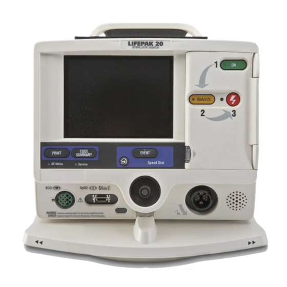
Basic Orientation CONTROLS, INDICATORS, AND CONNECTORS The following figures provide a brief description of the controls, indicators, and connectors for the LIFEPAK 20e defibrillator/monitor and CodeManagement Module. Figure 2-2 shows the front view of the LIFEPAK 20e defibrillator/monitor and Figure 2-3 shows the front view divided into seven areas. - Page 28 Basic Orientation Recommended Adult VF Dose: XXX-XXX-XXXJ DEFIBRILLATOR / MONITOR ENERGY SELECT Area 1 CHARGE Area 7 AED MODE ANALYZE LEAD SIZE SYNC PACER RATE Area 2 ALARMS CURRENT CODE Area 5 EVENT PRINT SUMMARY OPTIONS PAUSE Speed Dial AC Mains Service Area 3 SpO2...
- Page 29 Basic Orientation Area 1 Adult Ventricular Fibrillation Energy Label Refer to page G-2. Switches power on or off. Recommended Adult VF Dose: xxx-xxx-xxxJ ENERGY SELECT Selects energy levels in manual mode. Refer to page 4-14. AED MODE LED illuminates when AED mode is active.
-
Page 30: Area 3
Basic Orientation Area 3 LEAD Changes ECG lead. Refer to page 3-2. SIZE EVENT Changes ECG size. Activates user- Refer to page 3-2. defined events. Refer to page 2-7. HOME SCREEN ALARMS Returns immediately Activates and to Home Screen. silences alarms. Refer to page 2-7. -
Page 31: Area 4
Basic Orientation Options After pressing , the screen displays the overlay shown in Figure 2-7. Use the Speed OPTIONS Dial to scroll through and select menu choices. PATIENT Enters patient name, patient ID, location, age, and sex. PACING DATE/TIME Selects demand or Sets the date and nondemand pacing. - Page 32 Basic Orientation Area 4 The following paragraphs provide additional information about the Speed Dial and the therapy cable connector shown in Area Speed Dial Use the Speed Dial to scroll through and select the desired menu item either while viewing the monitor screen or while in Options mode.
- Page 33 Basic Orientation Area 5 PRINT Starts or stops the printer. CODE SUMMARY AC MAINS Prints a CODE SUMMARY LED illuminates when AC critical event record. power (line power) is Refer to page 6-2. connected and providing SERVICE power. Indicates that service is required.
-
Page 34: Area 7
Basic Orientation Area 7 Note: Your device may have either of two screen formats, depending on the software version. Refer to Figure 2-13 Figure 2-14 to find the format that matches your device. MONITORING AREA Displays heart rate, time, SpO , battery status indicator, indicators for VF/VT alarm and selected energy. - Page 35 Basic Orientation Battery Alarm Time Selected Status Icon Display Metronome Energy Indicator Icon MONITORING WAVEFORM PARAMETER CHANNEL AREA AREA Displays patient Displays up to values and alarm two waveform limits. channels. Refer to page 2-13. STATUS MESSAGE AREA Figure 2-14 Area 7 The following paragraphs provide additional information about Area...
- Page 36 Basic Orientation Monitoring Area—Pulse Rate. If the ECG is not active, the SpO monitor can display pulse rate. The pulse rate source is indicated by PR (SPO2) Monitoring Area—SpO (pulse oximeter). The oxygen saturation level is shown as a percentage from 50 to 100. Saturation below 50% is shown as <50%. A fluctuating bar graph represents the pulse signal strength.
-
Page 37: Changing Printer Paper
Basic Orientation Changing Printer Paper CAUTION! Possible printer malfunction. Using other manufacturers’ printer paper may cause the printer to function improperly and/or damage the print head. Use only the printer paper specified in these operating instructions. Loading 50 mm Paper The printer is equipped with an out-of-paper sensor to protect the printhead. -
Page 38: Back View
Basic Orientation Back View System connector Ground (equipotential) connector Refer to warning, page 2-16. ECG/Sync AC power connector connector Back View without CodeManagement Module Figure 2-16 Refer to warning, page 2-16. ECG/Sync connector AC power connector Ground (equipotential) System exhaust port Refer to warning, connector connector... -
Page 39: Side View Of Codemanagement Module
Basic Orientation WARNING! Shock hazard. All equipment connected to the system or ECG/sync connector must be battery powered or electrically isolated from AC power according to IEC 60601-1. For more information, contact Physio-Control Technical Support. System Connector For LIFEPAK 20e devices that do not have a CodeManagement Module attached, the system connector is used to transfer setup information to another LIFEPAK 20e device or connect to LIFENET ®... -
Page 40: Entering Patient Data
Basic Orientation The following paragraphs provide additional information about the side view. TrueCPR Device Port The TrueCPR device port is used to transfer data from the TrueCPR™ Coaching Device to the LIFENET System. Only the TrueCPR device should be connected to this port. Refer to "Data Transfer from TrueCPR Device,"... - Page 41 Basic Orientation 2 Rotate the Speed Dial to scroll through the alphabet. 3 Press the Speed Dial to select the desired character. The character appears in the highlighted area. 4 Repeat Step 2 and Step 3 until the name is complete. 5 Scroll and select to return to the Options/Patient screen as shown...
-
Page 42: Setting Alarms
Basic Orientation SETTING ALARMS Alarms for the LIFEPAK 20e defibrillator/monitor can be set to and are enabled when OFF, the monitor is turned on. When the alarms are set to , predetermined limits are set. To view these limits, press the button. - Page 43 Basic Orientation Select to turn on VF/VT ALARM continuous monitoring for ventricular fibrillation and ventricular tachycardia in manual mode. A symbol appears above the primary ECG when the alarm is on Reselect to turn off VF/VT ALARM this alarm. Note: When the VF/VT alarm is on, you are limited to PADDLES lead or lead II.
-
Page 44: Managing Alarms
Basic Orientation MANAGING ALARMS The alarm bell symbol indicates when alarms are on or off . All alarms that are controlled by QUICK SET have equal priority. When alarms are on and an alarm limit is exceeded, a tone sounds, the violated parameter flashes, and an alarm message appears on the screen. To manage an alarm: 1 Press . -
Page 45: Connecting To Power
Basic Orientation CONNECTING TO POWER The LIFEPAK 20e defibrillator/monitor and the optional CodeManagement Module operate on AC (line) power or their internal Lithium-ion batteries. You can switch from battery to AC power or AC power to battery while the device is on and in use by plugging in or unplugging the AC power cord. - Page 46 Basic Orientation recharge for a time period equivalent to the time the defibrillator was in use. For example, if the defibrillator was used one hour, the required recharge time will be approximately one hour. New batteries or batteries that have been stored for an extended time should be recharged before they are used.
- Page 47 Basic Orientation Battery Status Indicator Table 2-2 Battery Battery Battery Status Messages and Tones Capacity Indicator (percentage) Four green bars None 76–100 Three green bars None 51–75 Two green bars None 26–50 One green bar None 16–25 One yellow bar LOW BATTERY 11–15 Three beeps (one time).
-
Page 48: Codemanagement Module Battery
Basic Orientation CodeManagement Module Battery The CodeManagement Module has an internal, rechargeable Lithium-ion battery. When the CodeManagement Module is properly connected to the LIFEPAK 20e defibrillator and AC power, the batteries in the defibrillator and CodeManagement Module both recharge. When the device is disconnected from AC power, both the defibrillator and CodeManagement Module automatically switch to battery power. -
Page 50: Monitoring
MONITORING This section describes the monitoring features of the LIFEPAK 20e defibrillator/monitor. Monitoring the ECG page 3-2 Monitoring SpO Monitoring EtCO 3-16 LIFEPAK 20e Defibrillator/Monitor Operating Instructions ©2006-2015 Physio-Control, Inc. -
Page 51: Monitoring The Ecg
Monitoring MONITORING THE ECG The following subsections describe: • ECG Monitoring Warning • Selecting ECG Lead and Size • Adjusting the Systole Tone Volume • Monitoring ECG with Paddles Accessories • Monitoring with the Patient ECG Cable • Troubleshooting Tips for ECG Monitoring ECG Monitoring Warning WARNING! Possible misinterpretation of ECG data. -
Page 52: Adjusting The Systole Tone Volume
Monitoring To select or change the ECG lead using the Speed Dial: 1 Highlight and select , and CHANNEL 1 then select to obtain the LEAD primary ECG lead choices. 2 Change the ECG lead by rotating the Speed Dial. The highlighted selection shows the ECG lead. - Page 53 Monitoring Monitoring ECG with Paddles Accessories Anterior-lateral Placement Anterior-lateral placement is the only placement that should be used for ECG monitoring with paddles accessories. ♥ 1 Place either the therapy electrode or the apex paddle lateral to the patient’s left nipple in the midaxillary line, with the center of the electrode in the midaxillary line, if possible.
-
Page 54: Monitoring With The Patient Ecg Cable
Monitoring 3 Apply the therapy electrodes or standard paddles in the anterior-lateral position. For therapy electrodes, confirm that the package is sealed and the Use By date has not passed. For standard paddles, apply conductive gel over the entire electrode surface. 4 Connect the disposable therapy electrodes to the therapy cable. - Page 55 Monitoring 5 Apply ECG electrodes: • Confirm package is sealed and Use By date has not passed. • Attach an electrode to each of the lead wires. • Grasp electrode tab and peel electrode from carrier. • Inspect electrode gel and ensure the gel is intact (discard electrode if gel is not intact). •...
-
Page 56: Troubleshooting Tips For Ecg Monitoring
Monitoring Smaller amplitude internal pacemaker pulses may not be distinguished clearly. For improved detection and display of internal pacemaker pulses, turn on the internal pacemaker detector, and/or connect the ECG cable, select an ECG lead, and print the ECG in diagnostic frequency response. - Page 57 Monitoring Troubleshooting Tips for ECG Monitoring (Continued) Table 3-2 Observation Possible Cause Corrective Action Outdated, corroded, or dried- • Check date codes on electrode packages. out electrodes. • Use only silver/silver chloride electrodes with Use By dates that have not passed. •...
-
Page 58: Spo Warnings And Cautions
Monitoring MONITORING SpO The following paragraphs describe: • Warnings and Cautions • When to Use a Pulse Oximeter • How a Pulse Oximeter Works • Monitoring Considerations • Monitoring Procedure • Waveform • Volume • Sensitivity • Averaging Time • Pulse Oximeter Sensors •... -
Page 59: When To Use A Pulse Oximeter
Monitoring WARNINGS! (CONTINUED) Inaccurate pulse oximeter readings. Severe anemia, significant blood levels of carboxyhemoglobin or methemoglobin, elevated levels of total bilirubin, intravascular dyes that change usual blood pigmentation, excessive patient movement, venous pulsations, electrosurgical interference, exposure to irradiation and placement of the sensor on an extremity that has a blood pressure cuff, intravascular line or externally applied coloring (such as nail polish) may interfere with oximeter performance. -
Page 60: Spo Monitoring Considerations
Monitoring Sensor (holds LEDs Light emitting and detector) diodes Infrared Light receiving detector How a Pulse Oximeter Works Figure 3-4 The quality of the SpO reading depends on correct sensor size and placement, adequate blood flow through the sensor site, patient motion, and exposure to ambient light. For example, with very low perfusion at the monitored site, readings may read lower than core arterial oxygen saturation. -
Page 61: Spo Monitoring Procedure
Monitoring Monitoring Procedure The defibrillator controls power to the pulse oximeter. When the defibrillator is turned on, the oximeter turns on and performs a self-test that requires up to 10 seconds. When the defibrillator is turned off, the oximeter also turns off. To conserve battery power, the pulse oximeter goes into “sleep mode”... -
Page 62: Sensitivity
Monitoring Sensitivity The sensitivity setting allows you to adjust the oximeter for differing perfusion states. To adjust the sensitivity to either normal or high, highlight and select on the home screen and then SPO2 select SENSITIVITY The normal sensitivity setting is the recommended setting for most patients. The high sensitivity setting allows for SpO monitoring under low perfusion states such as the severe hypotension of shock. -
Page 63: Troubleshooting Tips For Spo
Monitoring Troubleshooting Tips for SpO Troubleshooting Tips for SpO Table 3-3 Observation Possible Cause Corrective Action 1 The oximeter measures a Excessive patient motion. • Keep patient still. pulse, but there is no oxygen • Check that sensor is secure. saturation or pulse rate. - Page 64 Monitoring Troubleshooting Tips for SpO (Continued) Table 3-3 Observation Possible Cause Corrective Action A sensor is connected to the • Refer to "Pulse Oximeter SPO2: UNKNOWN SENSOR Sensors," page 3-13 message appears. device that is not compatible sensor compatibility. with the Masimo Sp0 module.
-
Page 65: Monitoring Etco 2
Monitoring MONITORING ETCO The following paragraphs describe: • EtCO Warnings and Cautions • How Capnography Works • EtCO Monitoring Waveform Analysis • EtCO Monitoring Procedure • Display • Alarms • Detection • Cleaning • Troubleshooting Tips for EtCO EtCO Warnings and Cautions WARNINGS! Fire hazard. -
Page 66: How Capnography Works
Monitoring WARNINGS! (CONTINUED) Possible strangulation. Carefully route the patient tubing (FilterLine) to reduce the possibility of patient entanglement or strangulation. Infection hazard ® Do not reuse, sterilize, or clean Microstream accessories as they are designed for single- patient one-time use. Infection hazard Do not return air from the CO exhaust port to the breathing system. -
Page 67: Etco Monitoring Procedure
Monitoring Phases of the Respiratory Waveform Figure 3-5 Respiratory Baseline. Elevation of the waveform baseline (I–II segment) usually represents rebreathing CO . This elevation usually is accompanied by gradual increases in the EtCO value. Rebreathing CO is common in circumstances of artificially produced increased dead space and hypoventilation. - Page 68 Monitoring To monitor EtCO 1 Press 2 Select the appropriate EtCO accessory for the patient. Note: To decrease the likelihood of the FilterLine connection coming loose during use, hand-straighten the tubing after removal from the package before connecting to patient or device.
-
Page 69: Co 2 Display
Monitoring Display The following scales are available to display the CO waveform. The LIFEPAK 20e defibrillator/monitor automatically selects the scale based on the measured EtCO value. To change the CO scale, outline and select the CO area using the Speed Dial and then select the desired scale from the scale menu. -
Page 70: Co 2 Detection
Monitoring Detection A CO waveform appears when any CO is detected, but CO must be greater than 3.5 mmHg for a numerical value to be displayed. However, the CO module will not recognize a breath until the is at least 8 mmHg (1.0% or 1 kPa). Valid breaths must be detected in order for the apnea alarm to function and to count the respiratory rate (RR). -
Page 71: Troubleshooting Tips For Etco
Monitoring Troubleshooting Tips for EtCO Troubleshooting Tips for EtCO Table 3-4 Observation Possible Cause Corrective Action message No breath has been detected • Check the patient. ALARM APNEA appears and waveform is for 30 seconds since last valid solid line at or near zero. breath. - Page 72 Monitoring Troubleshooting Tips for EtCO (Continued) Table 3-4 Observation Possible Cause Corrective Action 8 EtCO values are Physiological cause such as • None. COPD. consistently higher than expected. Inadequate ventilation. • Check ventilator; increase ventilatory rate/bagging. Patient splinting during • Supporting measures such as pain relief.
- Page 73 Monitoring Troubleshooting Tips for EtCO (Continued) Table 3-4 Observation Possible Cause Corrective Action 15 CO does not appear on CodeManagement Module not • Contact qualified service personnel. properly connected to screen when FilterLine is defibrillator. connected. Low battery voltage. • Connect to AC power. Defective battery in •...
-
Page 74: Therapy
THERAPY This section describes patient therapy. General Therapy Warnings and Cautions page 4-2 Therapy Electrode and Standard Paddle Placement Automated External Defibrillation Manual Defibrillation 4-14 Pediatric Defibrillation 4-21 Noninvasive Pacing 4-25 LIFEPAK 20e Defibrillator/Monitor Operating Instructions ©2006-2015 Physio-Control, Inc. -
Page 75: General Therapy Warnings And Cautions
Therapy GENERAL THERAPY WARNINGS AND CAUTIONS WARNINGS! Shock hazard. The defibrillator delivers up to 360 J of electrical energy. When discharging the defibrillator, do not touch the paddle electrode surfaces or disposable therapy electrodes. Shock hazard. If a person is touching the patient, bed, or any conductive material in contact with the patient during defibrillation, the delivered energy may be partially discharged through that person. -
Page 76: Therapy Electrode And Standard Paddle Placement
Therapy THERAPY ELECTRODE AND STANDARD PADDLE PLACEMENT The following paragraphs describe therapy electrodes and standard paddles placement, including special placement situations. Anterior-lateral Placement Anterior-lateral placement allows for ECG monitoring, defibrillation, synchronized cardioversion, and noninvasive pacing. ♥ 1 Place either the or + therapy electrode, or apex paddle lateral to the patient's left nipple in the midaxillary line, with the center of the electrode in the midaxillary line, if possible. -
Page 77: Special Placement Situations
Therapy ANTERIOR POSTERIOR POSTERIOR ANTERIOR FAST-PATCH Electrodes QUIK-COMBO Electrodes Anterior-posterior Placement for Noninvasive Pacing or Defibrillation Figure 4-2 Special Placement Situations When placing therapy electrodes or standard paddles, be aware of the special requirements in the following possible situations. Synchronized Cardioversion Alternative anterior-posterior placements for cardioversion of supraventricular arrhythmias include: ♥... -
Page 78: Automated External Defibrillation
Therapy AUTOMATED EXTERNAL DEFIBRILLATION The following paragraphs include: • AED Warnings • AED Setup • AED Procedure • Special AED Setup Options • Troubleshooting Tips for AED Mode • Switching from AED to Manual Mode AED Warnings WARNING! Possible misinterpretation of data. Do not analyze while patient is moving or being transported. -
Page 79: Aed Procedure
Therapy The LIFEPAK 20e defibrillator/monitor can be setup to display the ECG waveform in AED mode or to not display a waveform. The operation in AED mode remains the same whether or not the ECG waveform is displayed. When the ECG waveform is set to the setup options (refer to Section 8), the... - Page 80 Therapy 3 Prepare the patient for electrode placement (refer to "Paddles Monitoring Procedure" page 3-4). message CONNECT ELECTRODES and voice prompt occur until the patient is connected to the AED. 4 Connect the therapy electrodes to the therapy cable, and confirm cable connection to the defibrillator.
- Page 81 Therapy You will see and hear STAND CLEAR, ) followed by a PUSH TO SHOCK “shock ready” tone. The shock LED flashes. Clear everyone away from the patient, bed, or any equipment connected to the patient. Press the button to discharge the AED.
- Page 82 Therapy No Shock Advised If the AED detects a nonshockable rhythm, you will see and hear . The AED will not SHOCK ADVISED charge, and a shock can not be delivered. After a prompt you NO SHOCK ADVISED will see and hear START CPR countdown timer (min:sec format) continues for the duration specified in...
-
Page 83: Special Aed Setup Options
Therapy After you remove the test plug from the therapy cable, the message and voice prompt occurs CONNECT ELECTRODES until the patient is connected to the AED. Motion Detected If motion is detected during the ECG analysis, you will see and hear MOTION followed by a DETECTED, STOP MOTION... - Page 84 Therapy Initial CPR - CPR First When the option is set to , you will be prompted to INITIAL CPR CPR FIRST START CPR immediately after the AED is turned on. You will see and hear START CPR After 3 seconds, a countdown timer continues for the duration specified in the initial CPR period and you will see and hear...
- Page 85 Therapy Shock Advised If the AED detects a shockable rhythm, you will see and hear START CPR followed by IF YOU WITNESSED THE . This provides ARREST, PUSH ANALYZE an opportunity to end the initial CPR early and proceed directly to delivering a shock.
-
Page 86: Troubleshooting Tips For Aed Mode
Therapy Troubleshooting Tips for AED Mode Troubleshooting Tips for AED Mode Table 4-1 Observation Possible Cause Corrective Action Inadequate connection to • Check for electrode CONNECT ELECTRODES message appears. connection. defibrillator. Electrodes do not adhere • Press electrodes firmly on patient’s skin. -
Page 87: Switching From Aed To Manual Mode
Therapy Switching from AED to Manual Mode If the front console door is closed, you can enter manual mode by pressing the button MANUAL located in the lower left corner of the door. This opens the door and automatically takes the defibrillator out of AED mode, allowing you to access manual mode defibrillation and pacing. -
Page 88: Manual Defibrillation Warnings
Therapy Manual Defibrillation Warnings WARNINGS! Possible fire, burns, and ineffective energy delivery. Precordial lead electrodes and lead wires may interfere with the placement of standard paddles or therapy electrodes. Before defibrillation, remove any interfering precordial lead electrodes and lead wires. Shock hazard. -
Page 89: Defibrillation Procedure
Therapy If the defibrillator is charged to 80 joules or more with paddles in the paddle wells, and then the paddles are removed and placed on a patient, the defibrillator continues charging to the selected energy and defibrillation may be completed as usual. When charging the defibrillator with the paddles on the patient’s chest, the defibrillator automatically adjusts the waveform voltage and current duration based on the patient's impedance. -
Page 90: Cpr Metronome
Therapy 11 Observe the patient and the ECG rhythm. If an additional shock is necessary, repeat the procedure beginning at Step 6. Note: If the message appears and the shock is not ABNORMAL ENERGY DELIVERY effective, increase energy, if necessary, and repeat shock. (Also refer to page 4-24.) CPR Metronome... -
Page 91: Synchronized Cardioversion Procedure
Therapy Activating and Deactivating the Metronome To activate the CPR metronome in Manual mode: 1 Use the Speed Dial to select the CPR Metronome icon. The CPR METRONOME Metronome menu appears and the Adult - No Airway metronome is activated using the Adult- Adult - Airway No Airway default setting. - Page 92 Therapy WARNING! Possible lethal arrhythmia. Ventricular fibrillation may be induced with improper synchronization. DO NOT use the ECG from another monitor (slaving) to synchronize the LIFEPAK 20e defibrillator/monitor discharge. Always monitor the patient’s ECG directly through the ECG cable, therapy cable or use the remote synchronization procedure.
-
Page 93: Remote Synchronization Procedure
Therapy Remote Synchronization Procedure WARNINGS! Possible lethal arrhythmia. Ventricular fibrillation may be induced with improper synchronization. The hospital’s biomedical engineering staff should perform synchronization delay measurements on the system, as a whole, to ensure that the 60 ms limit for synchronization delay is not exceeded, per requirements as specified in IEC 60601-2-4. -
Page 94: Pediatric Defibrillation
Therapy PEDIATRIC DEFIBRILLATION Pediatric paddles are part of the standard paddle set (refer to page 5-7). Pediatric Paddle Placement Pediatric paddles should be used for patients weighing less than 10 kg (22 lb) or for patients whose chest size cannot accommodate the adult therapy electrodes. Adult paddles are recommended if the paddles will fit completely on the patient’s chest. -
Page 95: Defibrillation Procedure
Therapy Defibrillation Procedure To defibrillate the patient: 1 Press to turn on the defibrillator. 2 To access the pediatric paddles, slide the adult paddle forward until it releases. 3 Apply defibrillation gel to the pediatric paddle electrode surfaces. 4 Select the appropriate energy for the weight of the child according to American Heart Association recommendations (or equivalent guidelines). - Page 96 Therapy Troubleshooting Tips for Defibrillation and Synchronized Cardioversion (Continued) Table 4-3 Observation Possible Cause Corrective Action 3 REMOVE TEST PLUG Test plug connected to • Disconnect test plug and message appears. connect electrodes to QUIK-COMBO therapy cable. QUIK-COMBO therapy cable. Radio frequency interference •...
- Page 97 Therapy Troubleshooting Tips for Defibrillation and Synchronized Cardioversion (Continued) Table 4-3 Observation Possible Cause Corrective Action Open air discharge with • Press paddles firmly on ABNORMAL ENERGY patient’s chest when message appears standard paddles. DELIVERY discharging. and Shock XJ Abnormal •...
-
Page 98: Noninvasive Pacing
Therapy NONINVASIVE PACING The LIFEPAK 20e defibrillator/monitor provides noninvasive pacing using QUIK-COMBO electrodes. The following paragraphs include: • Noninvasive Pacing Warnings • Demand and Nondemand Pacing • Noninvasive Pacing Procedure • Troubleshooting Tips for Noninvasive Pacing For information about noninvasive pediatric pacing, refer to the Physio-Control Therapy Electrodes Operating Instructions. -
Page 99: Noninvasive Pacing Procedure
Therapy The LIFEPAK 20e defibrillator/monitor has an integrated pulse oximeter that can be used in conjunction with a noninvasive pacemaker to help confirm capture. To confirm capture, compare the pulse rate measured by the oximeter to the set pacing rate of the pacemaker. Noninvasive Pacing Procedure ECG monitoring during pacing must be performed with the ECG electrodes and patient ECG cable. -
Page 100: Troubleshooting Tips For Noninvasive Pacing
Therapy If the monitor detects ECG leads off during pacing, pacing continues at a fixed rate until the ECG lead is reattached. During fixed-rate pacing, the pacemaker delivers pulses at the set pace rate regardless of any intrinsic beats that the patient may have. The monitor continues to display the pacing rate (ppm) and the current (mA). - Page 101 Therapy Troubleshooting Tips for Noninvasive Pacing (Continued) Table 4-4 Observation Possible Cause Corrective Action 5 Monitor screen displays ECG electrodes not optimally • Reposition electrodes away from pacing electrodes. distortion while pacing. placed with respect to pacing electrodes. Patient response to pacing is •...
- Page 102 PADDLE ACCESSORY OPTIONS Therapy Electrodes page 5-2 Standard Paddle Set (Optional) Sterilizable Internal Defibrillation Paddles LIFEPAK 20e Defibrillator/Monitor Operating Instructions ©2006-2015 Physio-Control, Inc.
-
Page 103: Paddle Accessory Options
Paddle Accessory Options THERAPY ELECTRODES The following paragraphs describe: • About Therapy Electrodes • Electrode Placement • Cable Connection • ECG Monitoring and Therapy Procedures • Replacing and Removing Electrodes • Testing • Cleaning and Sterilizing About Therapy Electrodes There are two pre-gelled, self-adhesive therapy electrodes available: QUIK-COMBO pacing/ defibrillation/ECG electrodes and FAST-PATCH defibrillation/ECG electrodes (Figure 5-1). -
Page 104: Electrode Placement
Paddle Accessory Options QUIK-COMBO Electrodes Table 5-1 Type Description Electrodes, with .6 m (2 ft) of lead wire, designed for QUIK-COMBO patients weighing 15 kg (33 lb) or more. Electrodes, providing a radio-transparent electrode and QUIK-COMBO - RTS lead wire set, designed for patients weighing 15 kg (33 lb) or more. -
Page 105: Cable Connection
Paddle Accessory Options Cable Connection To connect QUIK-COMBO electrodes to the QUIK-COMBO therapy cable: 1 Open the protective cover on the QUIK-COMBO therapy cable connector (refer to Figure 5-3). 2 Insert the QUIK-COMBO electrode connector into the therapy cable connector by aligning the arrows and pressing the connectors firmly together for proper attachment. -
Page 106: Replacing And Removing Electrodes
Paddle Accessory Options For pediatric patients, follow the procedures for ECG monitoring, manual defibrillation, synchronized cardioversion, and pacing except for the following: • Select the appropriate defibrillation energy for the weight of the pediatric patient according to the American Heart Association (AHA) recommendations or local protocol. Using energy levels of 100 joules or greater is likely to cause burns. -
Page 107: Testing
Paddle Accessory Options Disconnecting Defibrillation Cable from Test Post Figure 5-7 Testing As part of your defibrillator test routine, inspect and test the QUIK-COMBO therapy cable or FAST-PATCH defibrillation adapter cable. Daily inspection and testing will help ensure that the defibrillator and therapy cables are in good operating condition and are ready for use when ®... -
Page 108: Standard Paddle Set (Optional)
Paddle Accessory Options STANDARD PADDLE SET (OPTIONAL) The following paragraphs describe: • About the Standard Paddle Set • Accessing the Pediatric Paddles • Replacing the Adult Paddle Attachment • Cleaning the Standard Paddle Set Figure 5-8 illustrates the standard paddles’ features. Sternum Apex SHOCK button... -
Page 109: Replacing The Adult Paddle Attachment
Paddle Accessory Options 4 The pediatric paddle is now exposed and ready for use (refer to Figure 5-10). Adult paddle attachment Pediatric paddle Accessing a Pediatric Paddle Pediatric Paddle (Bottom) Figure 5-9 Figure 5-10 Replacing the Adult Paddle Attachment To replace the adult paddle attachment: 1 Hold the adult paddle attachment with one hand and the standard handle with the other hand. -
Page 110: Sterilizable Internal Defibrillation Paddles
Paddle Accessory Options STERILIZABLE INTERNAL DEFIBRILLATION PADDLES Physio-Control internal paddles are specifically designed for open chest cardiac defibrillation. Sterilizable Internal Defibrillation Paddles Figure 5-12 Internal paddles are available in several sizes. To order internal paddles, contact your Physio-Control representative or order online at store.physio-control.com (U.S. only). For complete information about using internal paddles to provide open chest cardiac defibrillation, see the Instructions for Use provided with the internal paddles. - Page 112 DATA MANAGEMENT This section describes data management functions. Overview of Data Storage and Retrieval page 6-2 CODE SUMMARY Report Managing Archived Patient Records Entering Archives Mode Printing Archived Patient Reports Transmitting Archived Patient Records Editing Archived Patient Records 6-10 Deleting Archived Patient Records 6-11 Overview of Connections for Transmitting Reports 6-12...
-
Page 113: Data Management
Data Management OVERVIEW OF DATA STORAGE AND RETRIEVAL The following paragraphs describe patient data storage and retrieval using the LIFEPAK 20e defibrillator/monitor. Data Storage When you turn on the LIFEPAK 20e defibrillator/monitor, you cr e a new Patient Record stamped with the current date and time. All events and associated waveforms are digitally stored in the Patient Record as patient reports, which you can print. -
Page 114: Event/Vital Signs Log
Data Management Figure 6-1 is an example of a CODE SUMMARY report. Press CODE SUMMARY to print the report. Preamble Name: DAVIDO, GUIDO CODE SUMMARY™ 041495094322 critical event record Patient ID: 52876004 Power On: 24 April 09 06:03:12 Location: L483 Device: Age: 45 Sex: M... -
Page 115: Waveform Events
Data Management Event Types Table 6-1 Event Types Events Monitoring • Initial rhythm • Alarm events • Vital signs Operator • Event • Print • Sync On/Off • Internal Pacer Detection On/Off initiated • Alarms On • VF/VT Alarm On/ Therapy •... -
Page 116: Code Summary Format
Data Management Waveform events are preceded by a header that includes the following information: • Patient data • Vital signs • Event name • Device configuration information • Therapy data • Transthoracic impedance measured during the shock (defibrillation events only) CODE SUMMARY Format You can configure the LIFEPAK 20e defibrillator/monitor to print a CODE SUMMARY report in one of the formats described in... - Page 117 Data Management Refer to Figure 6-2 for examples of waveform data event printouts in the CODE SUMMARY report. Check Patient Name: DAVIDO, GUIDO 041495094322 Patient ID: 52876004 Location: BF382 Age: 45 Sex: M 24 Apr 00 Check Patient 14:49:52 x1.0 .05-150Hz 25mm/s 010 123 35.1 3434 LP20PRB005 SpO2 Check Patient Event...
-
Page 118: Managing Archived Patient Records
Data Management MANAGING ARCHIVED PATIENT RECORDS When you turn off the LIFEPAK 20e defibrillator/monitor, the current Patient Record is saved in the archives. The following options are available for managing archived Patient Records: • Print archived patient reports • Transmit archived patient records •... - Page 119 Data Management 3 If the PATIENT and REPORT settings are correct, select PRINT to print the report. Otherwise, select PATIENT and proceed to the next step. 4 Select a patient from the list of Patient Records or select ALL PATIENTS to print a list of all Patient Records in the archives.
-
Page 120: Transmitting Archived Patient Records
Data Management TRANSMITTING ARCHIVED PATIENT RECORDS You can use the CodeManagement Module to transmit patient records to CODE-STAT™ Data Review Software via wireless connection to the LIFENET System. For information about configuring your CodeManagement Module to work in the LIFENET System, see the LIFENET System help documentation or contact your Physio-Control representative. -
Page 121: Editing Archived Patient Records
Data Management 5 Select SEND to transmit the report. Options / Archives / Send Data The transmission status appears in the status message area. Send 6 To cancel transmission, select ID: 20121108085518 Patient CANCEL , and then select YES . Cancel... -
Page 122: Deleting Archived Patient Records
Data Management DELETING ARCHIVED PATIENT RECORDS To delete: 1 Be sure that you are in the archives mode (refer to "Entering Archives Mode," page 6-7). 2 Select DELETE . 3 Select PATIENT . 4 Select a patient from the list. LIFEPAK 20e Defibrillator/Monitor Operating Instructions 6-11 ©2006-2015 Physio-Control, Inc. -
Page 123: Overview Of Connections For Transmitting Reports
Data Management 5 Select DELETE to permanently remove the selected Patient Record from the archives. Note: If, after you select DELETE , you decide you do not want to remove the patient record, immediately select UNDO . If you continue operations, you cannot reverse the DELETE selection. -
Page 124: Data Transfer From Truecpr Device
Data Management Maximum Distance: 1.0 m (3.28 feet) IrDA Adapter/ Defibrillator Computer IrDA Connections Figure 6-3 DATA TRANSFER FROM TrueCPR DEVICE Note: The TrueCPR device may not be available in all countries. Contact your local Physio-Control representative for more information. You can transfer data from the Physio-Control TrueCPR device to Physio-Control post-event review tools using the TrueCPR device port on the CodeManagement Module. -
Page 125: Troubleshooting Tips For Data Transmission
Data Management TROUBLESHOOTING TIPS FOR DATA TRANSMISSION Troubleshooting Tips for Data Transmission Table 6-4 Observation Possible Cause Corrective Action 1 SEND DATA option does CodeManagement Module not • Contact qualified service not appear in Options/ personnel. properly connected to Archives screen. defibrillator. -
Page 126: Maintaining The Equipment
MAINTAINING THE EQUIPMENT This section describes how to perform operator-level maintenance, testing, and troubleshooting for the LIFEPAK 20e defibrillator/monitor and selected accessories. For additional information about accessories, refer to specific accessory operating instructions. General Maintenance and Testing page 7-2 General Troubleshooting Tips 7-10 Service and Repair 7-12... -
Page 127: General Maintenance And Testing
Maintaining the Equipment GENERAL MAINTENANCE AND TESTING Periodic maintenance and testing of the LIFEPAK 20e defibrillator/monitor and accessories will help detect and prevent possible electrical and mechanical discrepancies. If testing reveals a possible discrepancy with the defibrillator or accessories, refer to "General Troubleshooting Tips,"... -
Page 128: Daily Auto Test
Maintaining the Equipment Daily Auto Test For routine testing and inspection, the user can rely on the daily auto test and the checks completed using the Operator's Checklist (refer to Appendix Each day at approximately 0300 (3:00am), the LIFEPAK 20e defibrillator/monitor automatically completes the following tasks: •... -
Page 129: User Test
Maintaining the Equipment QUIK-COMBO Test Plug Figure 7-1 User Test The LIFEPAK 20e defibrillator/monitor user test performs the same functions as the daily auto test (refer to the "Daily Auto Test" section). The manual user test is recommended if the daily auto test was not completed, if a test failure was reported, or if REDI-PAK electrodes are preconnected to the therapy cable as part of defibrillator readiness. -
Page 130: Cleaning
Maintaining the Equipment If the LIFEPAK 20e defibrillator/monitor detects a problem during the user test, the service LED lights and a printed report indicates that the test failed. Turn off the defibrillator and contact qualified service personnel. Refer to "General Troubleshooting Tips," page 7-10. -
Page 131: Standard Paddles Monitoring Check
Maintaining the Equipment Patient ECG Cable Check Equipment needed: • LIFEPAK 20e defibrillator/monitor • Fully charged batteries • Patient ECG cable 3-wire or 5-wire) • 3-lead or 12-lead simulator Procedure: 1 Press ON . 2 Connect the ECG cable to the defibrillator. 3 Connect all cable leads to the simulator. - Page 132 Maintaining the Equipment Procedure: Ensure the defibrillator is connected to AC power 4 hours prior to performing this test. The battery should be fully charged. 1 Disconnect the defibrillator from AC power. 2 Press ON . 3 Connect the ECG cable to the monitor and the patient simulator. 4 Turn on the simulator and select any rhythm except asystole or ventricular fibrillation.
-
Page 133: Therapy Cable Monitoring Check
Maintaining the Equipment Therapy Cable Monitoring Check Equipment needed: • LIFEPAK 20e defibrillator/monitor ® ® • QUIK-COMBO (or FAST-PATCH ) therapy cable • QUIK-COMBO 3-lead or 12-lead patient simulator, or posted patient simulator • Fully charged batteries Procedure: 1 Press ON . 2 Turn on the simulator and select normal sinus rhythm. -
Page 134: Therapy Cable Pacing Check
Maintaining the Equipment WARNING! Shock hazard. During defibrillation checks, the discharged energy passes through the cable connectors. Securely attach cable connectors to the simulator. 13 After the tone sounds, indicating full charge, press and hold SHOCK while observing the monitor screen. 14 Confirm the defibrillator discharges on the next sense QRS complex. -
Page 135: General Troubleshooting Tips
Maintaining the Equipment GENERAL TROUBLESHOOTING TIPS If a problem with the defibrillator/monitor is detected during operation or testing, refer to the troubleshooting tips in Table 7-2. If the problem cannot be corrected, remove the defibrillator/ monitor from use and contact qualified service personnel. General Troubleshooting Tips Table 7-2 Observation... - Page 136 Maintaining the Equipment General Troubleshooting Tips (Continued) Table 7-2 Observation Possible Cause Corrective Action 11 Date printed on report Date is incorrectly set. • Change the date setting. Refer to Section page 2-8. is incorrect. 12 Displayed messages Low battery power. •...
-
Page 137: Service And Repair
Maintaining the Equipment SERVICE AND REPAIR WARNINGS! Shock hazard. Do not disassemble the defibrillator. It contains no operator serviceable components and dangerous high voltages may be present. Contact qualified service personnel for repair. Possible ineffective energy delivery. Service mode is for authorized personnel only. Improper use of service mode may inappropriately alter the device’s configuration and may change energy output levels. -
Page 138: Accessories, Supplies, And Training Tools
The following accessories are approved for use with the LIFEPAK 20e defibrillator/monitor. To order, contact your Physio-Control representative or order online at store.physio-control.com. For non-CE marked accessories, see the LIFEPAK 20 Accessory Catalog. Note: The LIFEPAK 20e defibrillator/monitor and its accessories that are intended for direct or casual contact with the patient are latex-free. - Page 139 Maintaining the Equipment Other accessories • CodeManagement Module for use with the LIFEPAK 20e defibrillator/ monitor • QUIK-COMBO Test Plug • Docking Station • Serial Cable (system connector) • ECG recording paper ® • SIGNAGEL Electrode Gel • 3-Lead ECG Patient Simulator •...
- Page 140 SETUP OPTIONS This section describes how to select setup options for the LIFEPAK 20e defibrillator/monitor. Setup Options page 8-2 Entering Setup Options General Setup Menu Manual Mode Setup Menu AED Mode Setup Menu CPR Metronome Setup Menu Pacing Setup Menu Monitoring Menu Events Setup Menu 8-10...
-
Page 141: Setup Options
Setup Options SETUP OPTIONS Setup options allow you to define operating features for the LIFEPAK 20e defibrillator/monitor such as device identification numbers and default settings. Table 8-1 through Table 8-21 list all setup options along with the factory default settings. Setup options can be selected in either of two ways: •... -
Page 142: Entering Setup Options
Setup Options ENTERING SETUP OPTIONS To enter the Setup menu: 1 Press ON while holding down and EVENT. Continue to OPTIONS hold these controls down until the passcode screen appears. 2 Enter the passcode by scrolling through the digits in the highlighted fields. -
Page 143: General Setup Menu
Setup Options GENERAL SETUP MENU The General Setup menu allows you to define general purpose settings. When you select a menu item, the screen displays a help message. The underlined options are factory default settings. General Setup Menu Table 8-1 Menu Item Help Message Options... -
Page 144: Manual Mode Setup Menu
Setup Options MANUAL MODE SETUP MENU The Manual Mode Setup menu allows you to define defibrillation and synchronized cardioversion settings. When you select a menu item, the screen displays a help message. The underlined options are factory default settings. Manual Mode Setup Menu Table 8-2 Menu Item Help Message... - Page 145 Setup Options Manual Mode Energy Protocol Setup Menu Table 8-4 Menu Item Help Message Options PRESET Select preset energy FULL RANGE , PEDIATRIC . PROTOCOL protocol ENERGY 1 Select energy level for Full range: 100, 125, 150, 175 , 200 , 225, shock 1 250, 275, 300, 325, 360.
-
Page 146: Aed Mode Setup Menu
Setup Options AED MODE SETUP MENU The AED Mode Setup menu allows you to define automated external defibrillator (AED) settings. When you select a menu item, the screen displays a help message describing the option. The underlined options are factory default settings and are consistent with 2010 American Heart Association (AHA) and European Resuscitation Council (ERC) guidelines. -
Page 147: Cpr Metronome Setup Menu
Setup Options AED Mode CPR Setup Mode (Continued) Table 8-6 Menu Item Help Message Options PRESHOCK Set CPR interval after shock OFF, 15, 30 SECONDS advised decisions AED Mode Energy Protocol Setup Menu Table 8-7 Menu Item Help Message Options PRESET Select a preset energy Energy 1: 150 , 175 , 200 , 225 , 250 , 275 ,... -
Page 148: Pacing Setup Menu
Setup Options PACING SETUP MENU The Pacing Setup menu allows you to define noninvasive pacemaker settings. When you select a menu item, the screen displays a help message. The underlined options are factory default settings. Pacing Setup Menu Table 8-9 Menu Item Help Message Options... -
Page 149: Waveform Sets Setup Menu
Setup Options Waveform Sets Setup Menu Waveform Sets Setup Menu Table 8-12 Menu Item Help Message Options* CHANNEL 1 Select waveform for Channel 1 PADDLES, ECG LEAD I, ECG LEAD II, ECG LEAD III, (AVR, AVL, AVF, C CHANNEL 2 Select waveform for Channel 2 NONE , CASCADING ECG, PADDLES, ECG LEAD I, ECG LEAD II, ECG LEAD III, (AVR, AVL, AVF, C), SPO2, CO2... -
Page 150: Alarms Setup Menu
Setup Options ALARMS SETUP MENU The Alarms Setup menu allows you to define alarms and set the alarm volume level. When you select a menu item, the screen displays a help message. The underlined options are factory default settings. Alarms Setup Menu Table 8-15 Menu Item Help Message... -
Page 151: Auto Print Setup Menu
Setup Options Auto Print Setup Menu Auto Print Setup Menus Table 8-17 Menu Item Help Message Options DEFIBRILLATION Auto print defibrillation events or OFF . PACING Auto print pacing events or OFF . CHECK PATIENT Auto print check patient events ON or OFF . Auto print SAS events or OFF . -
Page 152: Reset Defaults Setup Menu
Setup Options RESET DEFAULTS SETUP MENU Use the Reset Defaults menu to configure the defibrillator for all factory default settings. Reset Defaults Setup Menu Table 8-19 Menu Item Help Message Options CANCEL Cancel and return to Setup Cancels reset operation. screen RESET Reset to factory configuration... -
Page 153: Set Passcodes Setup Menu
Setup Options SET PASSCODES SETUP MENU Use the Set Passcodes menu to change the factory default passcode of 0000 to some other number. If you lose the setup passcode, contact the factory for assistance. Set Passcodes Setup Menu Table 8-21 Menu Item Help Message Options... - Page 154 APPENDIX A SPECIFICATIONS AND PERFORMANCE CHARACTERISTICS LIFEPAK 20e Defibrillator/Monitor Operating Instructions ©2006-2015 Physio-Control, Inc.
- Page 156 Specifications and Performance Characteristics All specifications are at 20°C (68°F) unless otherwise stated. GENERAL Classification Defibrillator—Externally powered Class 1 with battery backup (per IEC 60601-1) Applied parts—ECG is Type CF patient connection. Therapy, SpO , and CO are Type BF patient connections (per IEC 60601-1).
- Page 157 Specifications and Performance Characteristics Battery Status Indicator Indicates available battery capacity for defibrillator. A Service Indicator When Error Detected. PHYSICAL CHARACTERISTICS Weight (maximum) Basic defibrillator/monitor: 5.31 kg (11.7 lb) Fully featured defibrillator/monitor (Pacing, SpO , and door) without paper or cables: 5.58 kg (12.3 lb) QUIK-COMBO cable, add: 0.20 kg (0.43 lb) For Standard (Hard) Paddles, add: 0.88 kg (1.95 lb) CodeManagement Module, add: 1.63 kg (3.6 lb)
- Page 158 Specifications and Performance Characteristics MONITOR ECG is monitored via several cable arrangements. A 3-wire cable is used for 3-lead ECG monitoring. A 5-wire cable is used for 3-lead ECG plus AVR, AVL, AVF, and C. Standard paddles or therapy electrodes (QUIK-COMBO pacing/ defibrillation/ECG electrodes or FAST-PATCH disposable defibrillation/ECG electrodes) are used for Paddles lead monitoring.
- Page 159 Specifications and Performance Characteristics Dynamic Signal Strength Bar Graph Pulse Tone at the Onset of the Pleth Waveform Averaging Time User selectable 4, 8, 12 or 16 seconds Data Update 1 second Period Alarm Condition 21 seconds (maximum time from physiological change to detection by device, with default 8 second averaging Delay selected)
- Page 160 Specifications and Performance Characteristics Range 0 to 99 mmHg (0 to 13.2 kPa) Units: mmHg, %, or kPa Accuracy* partial pressure at sea Accuracy: level: (0–80 bpm)** 0 to 38 mmHg ±2 mmHg (0 to 5.1 kPa) (0.27 kPa) 39 to 99 mmHg ±5% of reading + 0.8% for every 1 mmHg (0.13 kPa) (5.2 to 13.2 kPa)
- Page 161 Specifications and Performance Characteristics FREQUENCY RESPONSE Diagnostic Frequency 0.05 to 150 Hz or 0.05 to 40 Hz (user configurable) Response Monitor Frequency 0.67 to 40 Hz or 1 to 30 Hz (user configurable) Response Paddles Frequency 2.5 to 30 Hz Response Analog ECG Output 0.67 to 32 Hz (except 2.5 to 30 Hz for Paddles ECG)
- Page 162 Specifications and Performance Characteristics Waveform Shape and Measured Parameters Notes: T1 = duration of Phase 1 in milliseconds T2 = duration of Phase 2 in milliseconds Patient I1 (A) I2 (A) I3 (A) I4 (A) T1 (ms) T2 (ms) Impedance () 70.9 28.0 -28.0...
- Page 163 Specifications and Performance Characteristics Rated Energy Output * Energy setting selected Paddle Options QUIK-COMBO pacing/defibrillation/ECG electrodes (standard) FAST-PATCH disposable defibrillation/ECG electrodes (optional) Standard Paddles (optional) Internal Paddles (optional) Cable Length 2.4 m (8 ft) long QUIK-COMBO cable (not including electrode assembly) AED Mode Shock Advisory System...
- Page 164 Specifications and Performance Characteristics PACER Pacing Mode Demand or non-demand Rate and current defaults (user configurable) Pacing Rate 40 to 170 ppm Rate Accuracy ± 1.5% over entire range Output Waveform Monophasic, amplitude stable to ±5% relative to leading edge for currents greater than or equal to 40 mA, Duration 20 ±1 msec, Rise/Fall times <= 1 msec [10-90% levels] Output Current...
- Page 165 Specifications and Performance Characteristics CHARACTERISTIC Respiration, Leads Off The ECG leads off function uses AC current at 57.1 kHz for Sensing, Noise Cancellation sensing leads off, the disposable defibrillation electrodes use Current, and Voltage AC current at 57.1 kHz for leads off, and the ECG leads use a noise cancellation signal which ranges from DC to approximately 5k Hz.
- Page 166 Specifications and Performance Characteristics CHARACTERISTIC Accuracy Of Signal The device is a digital sampled data system. It meets Reproduction requirements for both test methods for diagnostic frequency response described in AAMI EC11. Audible Alarms This is a standalone device. All alarm tones are internal to the biphasic LIFEPAK 20e defibrillator/monitor.
- Page 167 Specifications and Performance Characteristics CHARACTERISTIC The alert tone shall consist of one set of two tones to precede voice prompts and to draw attention to the display. Specific characteristics shall be: • 1000 Hz square wave, 100 msec duration. • Silence, 100 msec duration. •...
- Page 168 Specifications and Performance Characteristics CHARACTERISTIC Priorities for Alarm Alarm conditions have the following priorities: Conditions Priority 1: • VF or VT detected based on ECG signal Priority 2: • Heart rate high or low limit exceeded • SpO high or low limit exceeded •...
- Page 169 Specifications and Performance Characteristics CHARGE TIME AC Operation Only: Maximum Time from Charge to Shock Ready Voltage Manual Mode AED Mode 100–120V 360 J 7 seconds 200 J 5 seconds 220–240V 360 J 7 seconds 200 J 5 seconds 90V (90% of Nominal -100) 360 J 7 seconds 200 J 5 seconds...
- Page 170 APPENDIX B CLINICAL SUMMARIES LIFEPAK 20e Defibrillator/Monitor Operating Instructions ©2006-2015 Physio-Control, Inc.
- Page 172 Clinical Summaries DEFIBRILLATION OF VENTRICULAR FIBRILLATION AND VENTRICULAR TACHYCARDIA Background Physio-Control conducted a multi-centered, prospective, randomized and blinded clinical trial of biphasic truncated exponential (BTE) shocks and conventional monophasic damped sine wave (MDS) shocks. Specifically, the equivalence of 200 J and 130 J BTE shocks to 200 J MDS shocks was tested.
- Page 173 Clinical Summaries Ventricular Tachycardia Seventy-two episodes of ventricular tachycardia (VT), induced in 62 patients, were treated with randomized shocks. High rates of conversion were observed with biphasic and monophasic shocks. Sample sizes were too small to statistically determine the relationship between success rates of the waveforms tested.
- Page 174 Clinical Summaries EXTERNAL CARDIOVERSION OF ATRIAL FIBRILLATION Overview The performance of the Physio-Control biphasic truncated exponential (BTE) waveform was compared to the conventional monophasic damped sine (MDS) waveform in an international, multi-center, prospective, randomized clinical study of adult patients undergoing elective cardioversion of atrial fibrillation (AF).
- Page 175 Clinical Summaries Cumulative Success Rates and Crossover Results for Cardioversion of AF Table B-1 Energy Setting 70 J 100 J 200 J 360 J 360 J Crossover Successes 4 of 5 pts succeeded with MDS: n = 37 5.4% 360 J BTE shock 0 of 1 pts succeeded with BTE: n = 35 360 J MDS shock...
- Page 176 Clinical Summaries 100% Energy Setting (J) Cumulative Shock Success for Cardioversion of Atrial Fibrillation with Monophasic (MDS) and Figure B-1 Biphasic (BTE) Shocks: Observed Rates (n) Plotted with Estimated Dose Response Curves Compared to monophasic shocks, biphasic shocks cardioverted atrial fibrillation with less peak current (14.0 ±...
- Page 177 Clinical Summaries Guidance for Selection of Shock Energy Biphasic waveform technology is a standard in cardiac defibrillators. The study summarized here provides the best information available on which to base energy selections for cardioversion with this waveform. For cardioversion of atrial fibrillation, the results of this study provide specific guidance for three possible strategies in selection of shock energy levels.
- Page 178 Clinical Summaries INTRA-OPERATIVE VENTRICULAR DEFIBRILLATION Overview The defibrillation efficacy of the Physio-Control biphasic truncated exponential (BTE) waveform was compared to the standard monophasic damped sine waveform (MDS) in a prospective, randomized multi-center study of patients undergoing intra-operative, direct defibrillation for ventricular fibrillation (VF).
- Page 179 Clinical Summaries Cumulative Shock Success Rates and Crossover Shock Results for Intra-operative Defibrillation Table B-3 Energy 20 J Crossover 10 J 20 J Setting Successes 3 of 8 pts succeeded with MDS: n = 41 20 J BTE shock 3 of 8 pts succeeded with BTE: n = 48* 20 J MDS shock *Two subjects randomized to the BTE group were unable to be included in the cumulative success rates shown...
- Page 180 Clinical Summaries Guidance for Selection of Shock Energy Biphasic waveform technology is a standard in cardiac defibrillators. The results of this study provide specific guidance for three possible strategies in developing a dosing regimen. • To optimize for lower initial and cumulative energy using a step-up protocol, select 5 J for the first shock and use small incremental increases in energy if further shocks are needed.
- Page 182 APPENDIX C SCREEN MESSAGES This appendix provides the Summary of Screen Messages table and describes screen messages that the LIFEPAK 20e defibrillator/monitor may display during operation. LIFEPAK 20e Defibrillator/Monitor Operating Instructions ©2006-2015 Physio-Control, Inc.
- Page 184 Screen Messages Table C-1 Summary of Screen Messages Message Description ABNORMAL ENERGY A discharge occurred when the paddles were shorted together (refer DELIVERY to warning, page 4-15); an open air discharge occurred; or, the patient impedance is out of range. This message may also appear in certain types of internal faults.
- Page 185 Screen Messages Table C-1 Summary of Screen Messages (Continued) Message Description CONNECT SYNC Remote sync is selected and the device is not connected to the CABLE TO REMOTE remote monitor. MONITOR CONNECT TO AC Remote sync is selected and the device is not connected to AC power. POWER CONNECT TO TEST Test plug not connected to QUIK-COMBO therapy cable or standard...
- Page 186 Screen Messages Table C-1 Summary of Screen Messages (Continued) Message Description LA LEADS OFF ECG electrode LA is disconnected. ECG electrode L is disconnected. L LEADS OFF ECG electrode LL is disconnected. LL LEADS OFF F LEADS OFF ECG electrode F is disconnected. LOW BATTERY Battery status indicator shows one yellow segment;...
- Page 187 Screen Messages Table C-1 Summary of Screen Messages (Continued) Message Description PUSH PADDLE If standard paddles are attached, the front panel SHOCK button is BUTTONS TO SHOCK! disabled. Message appears if you attempt to transfer energy by pressing the front panel SHOCK button. PUSH SHOCK The defibrillator is fully charged and ready to provide therapy (a BUTTON!
- Page 188 Screen Messages Table C-1 Summary of Screen Messages (Continued) Message Description STAND CLEAR/PUSH Stand clear of the patient and push the SHOCK button. SHOCK BUTTON START CPR Initiate CPR in AED mode. SWITCHING PRIMARY PADDLES lead is not available and you pressed the ANALYZE button. TO LEAD II SWITCHING PRIMARY PADDLES...
- Page 190 APPENDIX D OPERATOR’S CHECKLIST This Operator’s Checklist may be reproduced. LIFEPAK 20e Defibrillator/Monitor Operating Instructions ©2006-2015 Physio-Control, Inc.
- Page 192 20e Defibrillator/Monitor O perator’s Checklist LIFEPAK ® Unit Serial No.:________________________ Daily inspection and testing of the defibrillator/monitor using this Operator’s Checklist is recommended. This form may Location: ____________________________ be reproduced. Date Recommended Instruction Corrective Action Initials Insert a in the box after completing each instruction. 1 Check printed result of 3 A.M.
- Page 193 Date Recommended Instruction Corrective Action Initials User Test Performed 10 *Perform manual User Test if: • Hospital protocol requires more If User Test fails, contact qualified service frequent device testing than the personnel. recommended daily auto test • Daily auto test did not complete or did not print •...
- Page 194 APPENDIX E SHOCK ADVISORY SYSTEM This appendix describes the basic function of the Shock Advisory System. LIFEPAK 20e Defibrillator/Monitor Operating Instructions ©2006-2015 Physio-Control, Inc.
- Page 196 Shock Advisory System OVERVIEW OF THE SHOCK ADVISORY SYSTEM The Shock Advisory System™ is an ECG analysis system built into the LIFEPAK 20e defibrillator/monitor that advises the operator as to whether it detects a shockable or nonshockable rhythm. This system makes it possible for individuals who are not trained to interpret ECG rhythms to provide potentially lifesaving therapy to victims of ventricular fibrillation or pulseless ventricular tachycardia.
- Page 197 Shock Advisory System classified by clinical experts. The rhythms were selected to be a representative sample of rhythms seen during treatment of cardiac arrest. The Shock Advisory SystemTest Set contains the following ECG samples: • 168 each coarse ventricular fibrillation (VF) (>= 200 µV peak-to-peak amplitude) •...
- Page 198 Shock Advisory System Operator Control of Shock Therapy The Shock Advisory System causes the AED to charge automatically when it detects the presence of a shockable rhythm. When a shock is advised, the operator presses the SHOCK button to deliver the energy to the patient. Analysis is disabled while the device is charging or charged.
- Page 200 APPENDIX F SPO2 CLINICAL VALIDATION SUMMARIES This appendix describes clinical validation data for SpO monitoring. LIFEPAK 20e Defibrillator/Monitor Operating Instructions ©2006-2015 Physio-Control, Inc.
- Page 202 SpO2 Clinical Validation Summaries MASIMO CLINICAL VALIDATION DATA Masimo Corporation conducted clinical studies and tests to assess the accuracy of the SpO measurement function. The following paragraphs provide a summary of that data. Test Methods for Accuracy accuracy was determined by testing on healthy adult volunteers in the range of 60-100% against a laboratory CO-oximeter.
- Page 203 SpO2 Clinical Validation Summaries NELLCOR CLINICAL VALIDATION DATA Nellcor conducted clinical studies and tests to assess the accuracy of the SpO measurement function of the Nellcor SpO sensors. The following paragraphs provide a summary of that data. Test Methods for Accuracy accuracy specifications for Nellcor sensors are based on controlled hypoxia studies with healthy nonsmoking adult volunteers over the specified saturation SpO range.
- Page 204 APPENDIX G About cprMAX Technology LIFEPAK 20e Defibrillator/Monitor Operating Instructions ©2006-2015 Physio-Control, Inc.
- Page 206 About cprMAX Technology ABOUT cprMAX TECHNOLOGY Physio-Control cprMAX™ technology is designed to allow resuscitation protocols to maximize the quantity of CPR administered during treatment with an AED, consistent with the 2005 American Heart Association Guidelines for Cardiopulmonary Resuscitation and Emergency Cardiovascular Care (AHA Guidelines) and the European Resuscitation Council Guidelines for Resuscitation 2005...
- Page 207 About cprMAX Technology AED OPERATION WITH cprMAX TECHNOLOGY The following paragraphs describe AED operation with cprMAX technology setup options. Initial CPR option prompts the user to perform an initial period of CPR. The choices are: INITIAL CPR . The factory default is ANALYZE FIRST CPR FIRST •...
- Page 208 About cprMAX Technology Stacked Shocks When set to , the option inserts prompting for CPR after each (a single) STACKED SHOCKS shock. This eliminates the three-shock stack. CPR is prompted after the shock regardless of the ECG rhythm. The CPR time following the shock is determined by the setting CPR TIME 1 selected.
-
Page 210: Docking Station
APPENDIX H DOCKING STATION This appendix describes how to install and use the LIFEPAK 20e defibrillator/monitor docking station. LIFEPAK 20e Defibrillator/Monitor Operating Instructions ©2006-2015 Physio-Control, Inc. - Page 212 Docking Station LIFEPAK 20E DEFIBRILLATOR/MONITOR DOCKING STATION The LIFEPAK 20e defibrillator/monitor docking station allows you to secure your defibrillator to an emergency cart or other flat surface. The docking station provides a 360-degree turning radius for the viewing of the LIFEPAK 20e defibrillator/monitor display from any angle. Note: The docking station cannot be used with the CodeManagement Module.
- Page 214 APPENDIX I ELECTROMAGNETIC COMPATIBILITY GUIDANCE LIFEPAK 20e Defibrillator/Monitor Operating Instructions ©2006-2015 Physio-Control, Inc.
- Page 216 Electromagnetic Compatibility Guidance Table 1 Guidance and Manufacturer’s Declaration - Electromagnetic Emissions The LIFEPAK 20e defibrillator/monitor is intended for use in the electromagnetic environment specified below. The customer or the user of the LIFEPAK 20e defibrillator/monitor should ensure that the defibrillator/monitor is used in such an environment.
- Page 217 Electromagnetic Compatibility Guidance Table 2 Guidance and Manufacturer’s Declaration - Electromagnetic Immunity The LIFEPAK 20e defibrillator/monitor is intended for use in the electromagnetic environment specified below. The customer or the user of the LIFEPAK 20e defibrillator/monitor should ensure that the defibrillator/monitor is used in such an environment.
- Page 218 Electromagnetic Compatibility Guidance Table 3 Guidance and Manufacturer’s Declaration - Electromagnetic Immunity The LIFEPAK 20e defibrillator/monitor is intended for use in the electromagnetic environment specified below. The customer or the user of the LIFEPAK 20e defibrillator/monitor should ensure that the defibrillator/monitor is used in such an electromagnetic environment.
- Page 219 Electromagnetic Compatibility Guidance Table 4 Recommended Separation Distances between Portable and Mobile RF Communications Equipment and the LIFEPAK 20e Defibrillator/Monitor Series The LIFEPAK 20e defibrillator/monitor is intended for use in an electromagnetic environment in which radiated RF disturbances are controlled. The customer or the user of the LIFEPAK 20e defibrillator/monitor can help prevent electromagnetic interference by maintaining a minimum distance between portable and mobile RF communications equipment (transmitters) and the LIFEPAK 20e defibrillator/monitor as recommended below, according to the maximum output power of the communications equipment.
- Page 220 Electromagnetic Compatibility Guidance Table 5 CodeManagement Module Wireless Specifications The CodeManagement Module meets the following specifications for wireless transmission and reception, in accordance with IEC 60601-1-2. IEEE Protocol Frequency Modulation Bandwidth Effective Radiated Effective Radiated 802.11 (MHz) Type (MHz) Power (mW) Power (dbm) 802.11a 5180–5700...
- Page 222 INDEX Numerics Alarms Bradycardia 3-lead cable 3-5 Adjusting volume in OPTIONS 5-wire cable 3-5 Cable connectors 2-8 Limits 2-19 5-wire control, location of 2-10 Capnography Managing 2-21 Cardiopulmonary Resuscitation Quick Set 2-19 AC Mains indicator 2-10 (see CPR) Setting 2-19 CHARGE Control, location of 2-6 Accessories 7-13 Setup menu 8-11...
- Page 223 Index CodeManagement Module ECG size (screen) 2-11 Back view 2-15 Editing archived patient reports LEAD button 3-2 Front view 2-10 6-10 LEAD Control, location of 2-7 Installation 2-3 Electrodes Leads off messages 3-6 Side view 2-16 Placement 3-4, 4-3, 4-4 Limb leads 3-6 Wireless connection 6-9, 6-12 Placement, special situations...
- Page 224 Index SpO2 volume 3-12 PAUSE Control, location of 2-6 Waveform channel areas 2-11, Monitoring the ECG Pediatric paddles 5-1, 5-7 2-12, 2-13 Adjusting the systole volume 3-3 Defibrillation procedure 4-22 Screen Overlay (see Overlay) Motion Detection E-3 Placement 4-21 Selected energy (screen) 2-11 Removing 5-7, 5-8 Send Configuration Setup menu Preamble, CODE SUMMARY 6-3...
- Page 225 Index Noninvasive pacing 4-27 Indications SpO2 3-14 Monitoring , 3-9 Monitoring area on screen 2-13 Monitoring considerations 3-11 Unpacking and inspecting 2-3 Monitoring procedure 3-12 User Controls 2-7 Pulse Oximeter sensors 3-13 User testing 7-4 SpO2 Connector Connecting a cable 3-12 Location of 2-8 VF/VT Alarm Standard Paddles...
- Page 227 Physio-Control, Inc. 11811 Willows Road NE Redmond, WA 98052 USA Telephone: 425.867.4000 Toll Free (USA only): 800.442.1142 Fax: 425.867.4121 www.physio-control.com Physio-Control, Inc., 11811 Willows Road NE, Redmond, WA 98052 USA Physio-Control Operations Netherlands B.V., Galjoenweg 68, 6222 NV Maastricht, The Netherlands Publication date: 05/2015 3313187-009...
Need help?
Do you have a question about the LIFEPAK 20 and is the answer not in the manual?
Questions and answers
Does it matter where the pads are located? can it be right upper back and left side?
are both pads delivering the energy? or is one pad delivering and the other one receiving?