Physio Control LIFEPAK 20 Service Manual
Defibrillator/monitor
Hide thumbs
Also See for LIFEPAK 20:
- Manual (227 pages) ,
- Operating instructions manual (203 pages) ,
- Quick reference for clinical use (2 pages)

Related Manuals for Physio Control LIFEPAK 20


Summary of Contents for Physio Control LIFEPAK 20
- Page 1 LIFEPAK ® LIFEPAK 20e Defibrillator/Monitor SERVICE MANUAL ©2002-2016 Physio-Control, Inc. 3202007-005...
- Page 2 LIFEPAK 20/20e Defibrillator/Monitor Table of Contents Click a Topic Preface Safety Device Modes of Description Operation Performance Troubleshooting Preventive Battery Inspection Maintenance Maintenance Procedures Replacement LIFEPAK 20/20e Procedures Specifications Title Page Back Index Next Page...
- Page 3 Section Contents Preface This service manual describes how to maintain, test, troubleshoot, and repair the LIFEPAK 20 defibrillator/monitor or LIFEPAK 20e defibrillator/monitor (device). Separate publications, the LIFEPAK 20 Defibrillator/Monitor Operating Instructions (MIN 3200750) and LIFEPAK 20e Defibrillator/Monitor Operating Instructions (MIN 3205878), are used by physicians, clinicians, and emergency care providers.
- Page 4 LIFEPAK 20/20e Defibrillator/Monitor Section Contents Preface (continued) Contacting Physio-Control Responsibility for Information Device Tracking Service Information Warranty Information Configuration Information Glossary Acronyms Back Next Page Previous Page Table of Contents Index...
- Page 5 LIFEPAK 20/20e Defibrillator/Monitor Preface Trademarks LIFEPAK, FAST-PATCH, and QUIK-COMBO are registered trademarks of Physio-Control, Inc. CODE SUMMARY, REDI-PAK, and Shock Advisory System are trademarks of Physio-Control, Inc. Adobe and Acrobat are registered trademarks of Adobe Systems Incorporated. Fluke and Fluke Biomedical are registered trademarks.
- Page 6 LIFEPAK 20/20e Defibrillator/Monitor Preface Using Adobe Acrobat Reader Accessing Adobe This service manual opens in Adobe Acrobat Reader. The Adobe Reader can be downloaded for free at the Adobe internet URL http://www.adobe.com/ Reader Help products/reader.html. For additional assistance using the Adobe Reader...
- Page 7 LIFEPAK 20/20e Defibrillator/Monitor Preface Navigating Through the Manual Back Blue text indicates a hyperlink. Click a link to jump to that topic. Click in the navigation bar at the bottom of each page to return to your previous location. The pointer changes to a pointing finger when positioned over a link.
- Page 8 LIFEPAK 20/20e Defibrillator/Monitor Preface Viewing the PIP Checklist The LIFEPAK 20/20e device Performance Inspection Procedure Checklist is included on this CD-ROM. You can view this document by opening the file in Acrobat Reader. Previous Page Table of Contents Section Contents...
- Page 9 LIFEPAK 20/20e Defibrillator/Monitor Preface Service Personnel Qualifications Service technicians must be properly qualified and thoroughly familiar with the operation of the device. They must be familiar with and be able to read and understand the service manual. They must meet at least one of the following...
- Page 10 LIFEPAK 20/20e Defibrillator/Monitor Preface Contacting Physio-Control Physio-Control, Inc. 11811 Willows Road Northeast Redmond, WA 98052-2003 USA Telephone: 1.425.867.4000 Toll Free (USA only): 1.800.442.1142 Fax: 1.425.867.4121 Internet: www.physio-control.com Physio-Control Operations Netherlands B.V. Galjoenweg 68 6222 NV Maastricht The Netherlands Physio-Control Australia Pty Ltd Suite 4.01...
- Page 11 LIFEPAK 20/20e Defibrillator/Monitor Preface Responsibility for Information 1-10 This service manual describes the methods required to maintain, test, and repair the device. It does not address the operation of the device. Qualified service personnel must consult the appropriate operating instructions and this service manual to obtain a complete understanding of the use and maintenance of the device.
- Page 12 If your device has been sold, donated, lost, stolen, exported, or destroyed, or if it was not obtained directly from Physio-Control, please notify the device-tracking coordinator at 1.800.426.4448. Refer to your operating instructions for more information concerning device tracking.
- Page 13 Printed circuit board assemblies that require software may require installation by a Physio-Control Service representative. To obtain Physio-Control service and maintenance for your device, contact your local service or sales representative. In the USA, call Physio-Control Technical Support at 1.800.442.1142. Outside the USA, contact your local Physio-Control representative.
-
Page 14: Warranty Information
LIFEPAK 20/20e Defibrillator/Monitor Preface Warranty Information 1-13 Refer to the warranty statement provided with the LIFEPAK 20 defibrillator/ monitor. Masimo No Implied License — Possession or purchase of this device does not convey ® any express or implied license to use the device with replacement parts that... - Page 15 LIFEPAK 20/20e Defibrillator/Monitor Preface Battery Recycling Information 1-14 Recycle the device at the end of its useful life. Recycling assistance – The device should be recycled according to national ■ and local regulations. For instructions on disposing of this product or its accessories, see http://www.Physio-Control.com/recycling...
- Page 16 LIFEPAK 20/20e Defibrillator/Monitor Preface Configuration Information 1-15 This service manual covers existing devices and options through the following revisions: LIFEPAK 20/20e defibrillator/monitor basic device with ECG ■ Pacing option ■ SpO2 option ■ Previous Page Table of Contents Section Contents...
- Page 17 LIFEPAK 20/20e Defibrillator/Monitor Preface Glossary 1-16 The following are definitions of terms used throughout this service manual. Automated external defibrillator (AED) — The device uses an ECG analysis ■ Shock Advisory System™ to advise the device operator if it detects a shockable or nonshockable rhythm.
- Page 18 LIFEPAK 20/20e Defibrillator/Monitor Preface Glossary (continued) 1-17 Continuous patient surveillance system (CPSS) — A feature that monitors ■ the patient ECG in for a potentially shockable rhythm. LEADS PADDLES CPSS is active when the indicator is on or the AED MODE...
- Page 19 LIFEPAK 20/20e Defibrillator/Monitor Preface Glossary (continued) 1-18 REDI-PAK™ preconnect system — A variant of the QUIK-COMBO pacing/ ■ defibrillation/ECG electrodes system. The system allows QUIK-COMBO pacing/defibrillation/ECG electrode cable connection without removing the electrodes from their air-tight sealed pouch until needed.
- Page 20 LIFEPAK 20/20e Defibrillator/Monitor Preface Acronyms 1-19 The following is a list of acronyms and abbreviations used in this manual. Term Description AAMI Association for the Advancement of Medical Instrumentation Analog-to-digital conversion Automated external defibrillator Ampere hour American Heart Association ANSI...
- Page 21 LIFEPAK 20/20e Defibrillator/Monitor Preface Acronyms (continued) 1-20 .Acronyms Term Description DUART Dual universal asynchronous receiver/transmitter Electrocardiogram Emergency medical service Electrostatic discharge Electrosurgical unit Heart rate International Electrical Commission Liquid crystal display Light-emitting diode mmHg Millimeters of mercury NHAAP National Heart Attack Alert Program...
- Page 22 LIFEPAK 20/20e Defibrillator/Monitor Preface Acronyms (continued) 1-21 Term Description Performance inspection procedure Pulses per minute RISC Reduced instruction set computer Respiration rate RTC/NVRAM Real-time clock/non-volatile random-access memory Static-sensitive device Test and calibration procedure Volts, Alternating Current Ventricular fibrillation Ventricular tachycardia...
- Page 23 LIFEPAK 20/20e Defibrillator/Monitor Section Contents Safety This section describes the general safety conventions, terms, and symbols used in this service manual or on the device. This information is intended to alert service personnel to recommended precautions in the care, use, and handling of this medical device.
- Page 24 LIFEPAK 20/20e Defibrillator/Monitor Safety Terms The following terms are used in this service manual or on the various configurations of the device. Familiarize yourself with their definitions and significance. Danger: Immediate hazards that will result in serious personal injury or death.
- Page 25 LIFEPAK 20/20e Defibrillator/Monitor Safety General Warnings and Cautions The following are general warnings and cautions. Keep these warnings and cautions in mind when working with the device. More specific warnings and cautions appear throughout this service manual and the operating instructions.
- Page 26 LIFEPAK 20/20e Defibrillator/Monitor Safety General Warnings and Cautions (continued) WARNING Shock hazard. To avoid the risk of electrical shock, this equipment must only be connected to a supply mains with protective earth. All equipment connected to the system or ECG/sync connector must be battery powered or electrically isolated from AC power according to EN 60601-1.
- Page 27 LIFEPAK 20/20e Defibrillator/Monitor Safety Symbols The following list includes symbols that may be used in this service manual or on various configurations of the device and accessories. Some symbols may not be relevant to your device or used in every country.
- Page 28 LIFEPAK 20/20e Defibrillator/Monitor Safety Symbols (continued) Equipotential connector Positive terminal Negative terminal AC voltage DC voltage On (power: connection to the ac mains) Off (power: disconnection from the ac mains) Power on/off Switch on Switch off [signal] Input (Continued on next page)
- Page 29 LIFEPAK 20/20e Defibrillator/Monitor Safety Symbols (continued) [signal] Output Sync in/ECG out System connector/data in button HOME SCREEN Alarm off Alarm on Biphasic defibrillator shock Shock button Shock count (x) on screen Joules (Continued on next page) Previous Page Table of Contents...
- Page 30 LIFEPAK 20/20e Defibrillator/Monitor Safety Symbols (continued) Adult defibrillation paddle Infant defibrillation paddle Pace arrow, internal pacing Pace arrow, noninvasive pacing R-wave sense marker Event marker Heart rate Greater than Less than (Continued on next page) Previous Page Table of Contents...
- Page 31 LIFEPAK 20/20e Defibrillator/Monitor Safety Symbols (continued) VF/VT alarm on VF/VT alarm silenced Battery status indicator Fuse Static-sensitive device (SSD) Mark of conformity according to the European Medical Device Directive 93/42/EEC Canadian Standards Association certification for Canada and the United States...
- Page 32 LIFEPAK 20/20e Defibrillator/Monitor Safety Symbols (continued) 2-10 Device to device cable Turn counterclockwise to unlock YYYY Manufacture (date of manufacture) Serial number Catalog number used for placing orders Manufacturer’s item number Authorized EC representative Reorder number Use by date shown: yyyy-mm-dd...
- Page 33 LIFEPAK 20/20e Defibrillator/Monitor Safety Symbols (continued) 2-11 Do not dispose of this product in the unsorted municipal waste stream. Dispose of this product according to local regulations. See www.physio-control.com/recycling instructions on the proper disposal of this product. Symbol for China RoHS indicating the Environmentally...
- Page 34 LIFEPAK 20/20e Defibrillator/Monitor Safety Symbols (continued) 2-12 Recommended storage temperatures This end up Use only Li-ion batteries. Do not use NiMH batteries in this device. Previous Page Table of Contents Section Contents Back Index Next Page...
- Page 35 LIFEPAK 20/20e Defibrillator/Monitor Section Contents Device This section includes the following topics: Introduction Description Physical Description and Features Ordering Devices, Supplies, and Accessories System Context Diagrams Functional Description Index Next Page Previous Page Table of Contents Back...
- Page 36 Device Description Introduction About the Device The LIFEPAK 20/20e defibrillator/monitor (device) is a complete, acute, cardiac- care response system with both manual and semiautomatic defibrillation operation. When clinically indicated, the device enables the operator to deliver a brief, high-energy pulse of electricity to the patient’s heart. Operators can preconfigure the device to reduce complexity during normal operation.
- Page 37 LIFEPAK 20/20e Defibrillator/Monitor Device Description Introduction (continued) Manual Mode manual mode indicator off), the device enables the operator to AED MODE manually select an energy level, initiate a charge sequence, and apply energy in Operation either direct or synchronized modes. When the operator selects the...
- Page 38 LIFEPAK 20/20e Defibrillator/Monitor Device Description Introduction (continued) Device Primary The device has four primary functions: Functions Defibrillation ■ – Manual or semi-automatic (AED) defibrillation – Synchronized cardioversion in manual mode – Leads-off detection for therapy and ECG electrodes Noninvasive pacing ■...
-
Page 39: Table Of Contents
LIFEPAK 20/20e Defibrillator/Monitor Device Description Introduction (continued) Assemblies The device consists of a three-piece case assembly and optional extension module that enclose the following modules/PCBs: 1. System Control PCB 4. Therapy PCB 2. Patient Parameter PCB 5. User Interface PCB 3. - Page 40 LIFEPAK 20/20e Defibrillator/Monitor Device Description Introduction (continued) Device Classifications Defibrillator—Externally powered Class 1 device with battery backup. per IEC 60601-1 Applied parts—ECG is a Type CF patient connection. Therapy, SpO2, and CO2 are Type BF patient connections. Internal electrodes are a Type CF patient connection.
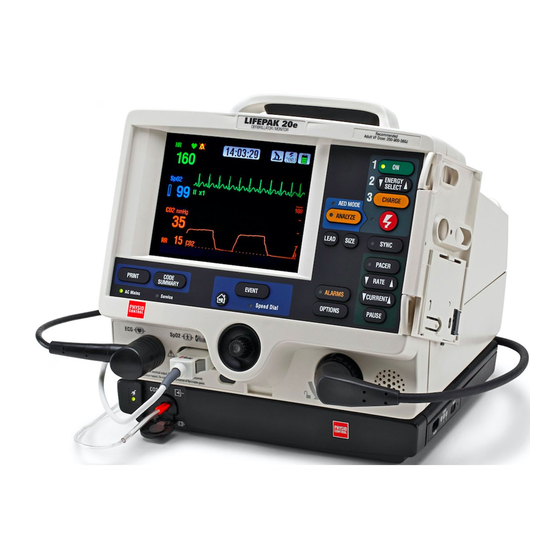
- Page 41 LIFEPAK 20/20e Defibrillator/Monitor Device Description Physical Description and Features LIFEPAK 20/20e For information about the buttons, indicators and connectors shown below, click the appropriate right arrow on the items bar at the bottom of the page. Front Panel 27 26...
- Page 42 LIFEPAK 20/20e Defibrillator/Monitor Device Description Physical Description and Features (continued) LIFEPAK 20/20e Number Description Front Panel Display screen — Color liquid crystal display (LCD) screen displays (continued) operating messages, waveforms, status messages, setup menus, and so forth. control — Press to activate user-defined events.
-
Page 43: Front Panel
LIFEPAK 20/20e Defibrillator/Monitor Device Description Physical Description and Features (continued) LIFEPAK 20/20e Number Description Front Panel Service indicator LED — Illuminates when the device enters (continued) service error codes into the Service Log (accessed through the menu). Refer to Troubleshooting... - Page 44 LIFEPAK 20/20e Defibrillator/Monitor Device Description Physical Description and Features (continued) 3-10 LIFEPAK 20/20e Number Description Front Panel control — Press to access the menu. OPTIONS OPTIONS (continued) Therapy cable connector — Connection port for the following: – QUIK-COMBO electrodes (standard) –...
- Page 45 LIFEPAK 20/20e Defibrillator/Monitor Device Description Physical Description and Features (continued) 3-11 LIFEPAK 20/20e Number Description Front Panel control — Press to activate the pacer function. PACER (continued) control — Press to activate the synchronized mode. SYNC control — Press to discharge the device.
- Page 46 LIFEPAK 20/20e Defibrillator/Monitor Device Description Physical Description and Features (continued) 3-12 LIFEPAK 20/20e Side Panel Printer — Prints ECG waveforms, CODE SUMMARY reports, and related information Printer button — Opens printer door (for paper installation) Previous Page Table of Contents...
- Page 47 LIFEPAK 20/20e Defibrillator/Monitor Device Description Physical Description and Features (continued) 3-13 LIFEPAK 20/20e Back Panel Number Description AC power connector — Connection port for ac (line) power. See Warning - Shock hazard on Page 2-4. System connector — Connection port for RS-232 serial interface.
- Page 48 LIFEPAK 20/20e Defibrillator/Monitor Device Description Physical Description and Features (continued) 3-14 What Is Shipped with a A basic device includes the components shown below. For additional information about components, refer to Accessories, Supplies, and Training Tools in the Basic Device Maintaining the Equipment section of the operating instructions.
- Page 49 50-mm printer paper (package of 3) 804700-003 11240-000013 ■ LIFEPAK 20e In-Service DVD Assembly 3308666-000 21300-008075 ■ Power cord 803650 ■ LIFEPAK 20 Quick Guide, Clinical Training 3205874-002 26500-001960 ■ Accessory order form 3202149-001 26500-001050 ■ QUIK-COMBO QUIK-COMBO therapy cables 3006570-007 11110-000040 ■...
- Page 50 LIFEPAK 20/20e Defibrillator/Monitor Device Description Ordering Devices, Supplies, and Accessories (continued) 3-16 Item Description CAT. SpO2 -option LNOP reusable adult finger sensor 3201655-003 11171-000007 ■ ® LNOP SpO2 cable, 2.4 m (8 ft) 3201655-001 11171-000008 ■ LNCS reusable adult finger sensor...
- Page 51 LIFEPAK 20/20e Defibrillator/Monitor Device Description System Context Diagrams 3-17 Front of Device The system context diagrams illustrate how the device connects with external equipment, including accessories, batteries, and power devices. (3) rolls 50 mm printer paper QUIK-COMBO therapy cable (QUIK-COMBO...
- Page 52 LIFEPAK 20/20e Defibrillator/Monitor Device Description System Context Diagrams (continued) 3-18 Back of Device Grounding stud System connector AC power cord ECG/sync connector Previous Page Table of Contents Section Contents Back Index Next Page...
- Page 53 Functional Description 3-19 Introduction The LIFEPAK 20/20e defibrillator/monitor is a medical device capable of combining a variety of therapeutic and monitoring features. In addition to automatic defibrillation, semiautomatic defibrillation, manual defibrillation, and noninvasive pacing, the device offers SpO2 and ECG monitoring. This device should be used indoors only (for example, a hospital or therapy center) and is powered by ac (line) power.
- Page 54 LIFEPAK 20/20e Defibrillator/Monitor Device Description Functional Description (continued) 3-20 System Block Diagram Click a link in the diagram below to view the descriptive text. A05 User Interface PCB A01 System PCB Speaker Audio Keypad A04 Therapy PCB Output Paddles Relay...
-
Page 55: System Control Pcb
LIFEPAK 20/20e Defibrillator/Monitor Device Description Functional Description (continued) 3-21 A01 System Control A01 System Control PCB provides the central control for the device. A reduced instruction set computing (RISC) processor, along with a real-time clock and digital memory, serve as the central processing unit (CPU). A companion chip provides most of the discrete interfaces required within the device, including the RS-232 and IrDA external communication ports. - Page 56 LIFEPAK 20/20e Defibrillator/Monitor Device Description Functional Description (continued) 3-22 A01 System Control Paddles ECG Pre-Amplifier — The paddles ECG pre-amplifier performs ■ patient-isolation, low-pass bandwidth filtering, and ECG sampling by means PCB (continued) of an analog-to-digital conversion (ADC) for the ECG signal received via the therapy paddles.
-
Page 57: Patient Parameter Pcb
LIFEPAK 20/20e Defibrillator/Monitor Device Description Functional Description (continued) 3-23 A02 Patient Parameter A02 Patient Parameter PCB collects ECG and SpO2 patient data, with the exception of the paddles ECG data, and provides preprocessed data to the system controller for AED and R-wave algorithms, alarm control, operator display and printout, and storage. -
Page 58: Power Module
LIFEPAK 20/20e Defibrillator/Monitor Device Description Functional Description (continued) 3-24 A02 Patient Parameter ECG Pre-Amplifier — The ECG pre-amplifier performs the function of ■ patient-isolation, low-pass bandwidth filtering, and ECG sampling through PCB (continued) the analog-to-digital conversion (ADC) for the ECG signal received through the W06 ECG Connector. - Page 59 Low voltage is detected by the A09 AC Power Supply Module and broadcast to the other PCBs through the device internal communication buses. Battery Charger (LIFEPAK 20 defibrillator/monitor) — The battery charger ■ is a constant current charger designed specifically to support the A07 NiMH Battery selected for the device.
- Page 60 LIFEPAK 20/20e Defibrillator/Monitor Device Description Functional Description (continued) 3-26 A03 Power Module Battery Charger (LIFEPAK 20e defibrillator/monitor) — The battery charger ■ is a constant current-constant voltage charger designed specifically to (continued) support the A07 Lithium Ion Battery selected for the device. Li-ion batteries...
- Page 61 LIFEPAK 20/20e Defibrillator/Monitor Device Description Functional Description (continued) 3-27 A04 Therapy PCB A04 Therapy PCB controls the pacing and defibrillation therapy features. The primary communication between the A04 Therapy PCB and the remainder of the device is through the data bus. A microprocessor and digital memory make up the central processing unit (CPU) that manages communication with the A01 System Control PCB.
- Page 62 LIFEPAK 20/20e Defibrillator/Monitor Device Description Functional Description (continued) 3-28 A04 Therapy PCB Power Switch — A power switch is a control circuit that detects the ■ button selection from the A05 User Interface PCB or a timer event from the (continued) A01 System Control PCB to power up the device.
- Page 63 LIFEPAK 20/20e Defibrillator/Monitor Device Description Functional Description (continued) 3-29 A04 Therapy PCB H-Bridge — The H-Bridge is a patient-isolated circuit that creates the ■ biphasic defibrillation waveform. A combination of silicon controlled rectifiers (continued) (SCR) and insulated gate bipolar transistors (IGBT) are used to place a positive-oriented defibrillation pulse across the patient load, followed immediately by a negative-oriented defibrillation pulse.
- Page 64 LIFEPAK 20/20e Defibrillator/Monitor Device Description Functional Description (continued) 3-30 A05 User Interface PCB A05 User Interface (UI) PCB is responsible for the presentation of the acquired data to the screen display and to the printer, and for receiving all user input.
- Page 65 LIFEPAK 20/20e Defibrillator/Monitor Device Description Functional Description (continued) 3-31 A05 User Interface PCB Field-Programmable Gate Array (FPGA) — The Field-Programmable Gate ■ Array (FPGA) provides the interface between the CPU and all the user (continued) interface peripherals. The FPGA works in conjunction with the CPU to provide the 1/4 VGA signals to the A11 Display, the data and strobe signals to the A12 Printer, and drive circuitry for the keypad LEDs.
- Page 66 A10 SpO2 Module and routes them to the A02 Patient Parameter PCB. A07 Battery On the LIFEPAK 20 defibrillator/monitor, the A07 Battery is a minimum 2.7 Ah (2.560 Ah per IEC 61951-2:2011), 12 V, NiMH battery that is used as an internal backup power source when ac power is not available.
- Page 67 LIFEPAK 20/20e Defibrillator/Monitor Device Description Functional Description (continued) 3-33 A07 Battery On the LIFEPAK 20e defibrillator/monitor, the Li-ion battery technology was selected for the same reasons as NiMH, but they are even lighter in weight. (continued) Li-ion batteries require a constant current-constant voltage charger that is provided by the A03 Power Module when the device is connected to ac power.
- Page 68 LIFEPAK 20/20e Defibrillator/Monitor Device Description Functional Description (continued) 3-34 A10 SpO2 Module A10 SpO2 Module can be the Masimo MS-5, MS-11 or MS-2011 oximetry module. This patented OEM module performs all functions related to oxygen saturation measurement, including sensor drive. Measurement results are...
- Page 69 LIFEPAK 20/20e Defibrillator/Monitor Device Description Functional Description (continued) 3-35 A13 Energy Capacitor A13 Energy Capacitor is a metallized film capacitor used for energy storage. The energy capacitor stores energy for both pacing and defibrillation therapies. The actual capacitance of the energy capacitor is calculated during the defibrillation calibration procedure.
- Page 70 LIFEPAK 20/20e Defibrillator/Monitor Device Description Functional Description (continued) 3-36 A15 Elastomer Keypad A15 Elastomer Keypad displays the common device controls (those not available using the ). The number of keys on this keypad varies, SPEED DIAL depending on the features installed in a specific device.
-
Page 71: Speaker
LIFEPAK 20/20e Defibrillator/Monitor Device Description Functional Description (continued) 3-37 W02 Speaker Assembly W02 Speaker Assembly is used to deliver device tones and voice prompts, including warnings and alarms. The OEM W02 Speaker is a small, compact, low- profile speaker capable of producing a one-watt output with a frequency response from 300 to 7000 Hz. - Page 72 W04 Speed Dial W04 Speed Dial Assembly is a rotary data entry device mounted on the LIFEPAK 20/20e defibrillator/monitor front case. It is used to control menu Assembly access and selection for user functions that are not supported directly by hard keys on the keypad.
- Page 73 Therapy PCB Cables the A04 Therapy PCB at J16 and to the A03 Power Module at J41. On the LIFEPAK 20 defibrillator/monitor, W10 is hardwired to the A03 Power Module and connects to the A04 Therapy PCB at J17. On the LIFEPAK 20e defibrillator/monitor, W10 connects to the A04 Therapy PCB at J17 and to the A03 Power Module at J51.
-
Page 74: Printer
W13 AC Power Cable The W13 AC Power Cable connects the A09 AC Power Supply Module at J02 with the A03 Power Module (hard-wired connection) for the LIFEPAK 20 defibrillator/monitor, and at J49 for the LIFEPAK 20e defibrillator/monitor. W14 Printer Flex Cable The W14 Printer Flex Cable connects the A05 UI PCB at J34 with the A03 Power Module at J45 and the A12 Printer. - Page 75 LIFEPAK 20/20e Defibrillator/Monitor Device Description Functional Description (continued) 3-41 W19 – W24 Grounding The W19 through W24 Grounding Cables provide grounding paths for various device components. Cables W25 Speaker Harness The W25 Speaker Harness Extension Cable connects the W02 Speaker Assembly to the A01 System PCB at J5.
- Page 76 LIFEPAK 20/20e Defibrillator/Monitor Section Contents Modes of When the device is turned on, it operates in one of five modes. Choose from the following links to learn more about a particular operating mode. Operation Manual Mode AED Mode Setup Mode...
- Page 77 LIFEPAK 20/20e Defibrillator/Monitor Modes of Operation Manual Mode Turning On the Device Manual mode enables the user to determine when to deliver a shock. in Manual Mode To configure the device to turn on in manual mode (the default is AED mode): 1.
- Page 78 LIFEPAK 20/20e Defibrillator/Monitor Modes of Operation Manual Mode (continued) Starting Manual Mode If the LED is on when the device is turned on, the device is in AED MODE Mode. from AED Mode To enter manual mode: Open the door (if installed) by pressing the button on the lower left ■...
- Page 79 LIFEPAK 20/20e Defibrillator/Monitor Modes of Operation AED Mode In AED mode (the default setting), the device automatically evaluates the patient rhythm to determine if a shock is needed and prompts the user to press the button to deliver a shock.
-
Page 80: Setup Mode
LIFEPAK 20/20e Defibrillator/Monitor Modes of Operation Setup Mode Introduction The operating defaults for the device are configured in the menu. Options SETUP include manual mode AED mode operating characteristics, alarm setup, time-of-day clock, and others. There is also a factory-reset option that resets the device to the factory default settings, except the maintenance interval, which remains unchanged. - Page 81 LIFEPAK 20/20e Defibrillator/Monitor Modes of Operation Setup Mode (continued) Displaying the Setup To display the menu: SETUP Menu 1. Press and hold the buttons, and then press the OPTIONS EVENT button. When the overlay appears, release the buttons. ENTER PASSCODE LED illuminates, indicating that the is active.
- Page 82 LIFEPAK 20/20e Defibrillator/Monitor Modes of Operation Setup Mode (continued) Setup Menu Options The following table defines the menu options. SETUP Note: Refer to the Defining Setup Options section in the operating instructions for complete descriptions of all options. Option Description...
- Page 83 Configuration If the device owner has a LIFENET System account, then use the LIFENET ■ Device Agent application to manage setup configurations. The LIFEPAK 20 configuration transfer cable can be used to transfer the ■ setup configuration to another device. After service is complete, transfer the configuration back to the original device.
- Page 84 LIFEPAK 20/20e Defibrillator/Monitor Modes of Operation Setup Mode (continued) Saving the Setup Another way to save the setup configuration is to use menu to print ■ SETUP the setup configuration. When service is complete, you can verify the Configuration setup and then manually reset the configuration.
- Page 85 LIFEPAK 20/20e Defibrillator/Monitor Modes of Operation Setup Mode (continued) 4-10 Creating a Passcode – Set the device to any of the following protocols (refer to ■ ARCHIVES ACCESS the table above): 1. Allow unlimited access to archives mode and allow records to be deleted.
- Page 86 LIFEPAK 20/20e Defibrillator/Monitor Modes of Operation Service Mode 4-11 Introduction The service mode functions enable qualified service technicians to: Function Description *Perform device Defibrillation ■ calibration routines Calibration *Perform device tests Keypad Test Printer Test ■ ■ Pixels Test Audio Test ■...
- Page 87 LIFEPAK 20/20e Defibrillator/Monitor Modes of Operation Service Mode (continued) 4-12 Displaying the Service To display the menu: SERVICE 1. Display the menu. Menu SETUP 2. Select from the menu. SERVICE SETUP 3. Enter the service mode passcode ( 0000 5433 4.
- Page 88 LIFEPAK 20/20e Defibrillator/Monitor Modes of Operation Service Mode (continued) 4-13 Setting the Service To set a service mode passcode: Mode Passcode 1. Select in the menu. The SET PASSCODE SERVICE SERVICE/SET PASSCODE overlay appears. 2. Enter a passcode by rotating the...
- Page 89 Service Mode (continued) 4-14 Setting a Maintenance The LIFEPAK 20 defibrillator/monitor can be set to display a screen message that alerts the user when the maintenance prompt interval date has passed. The Prompt Interval screen message appears on the screen for the first MAINTENANCE DUE 10 minutes after the device is powered on.
- Page 90 LIFEPAK 20/20e Defibrillator/Monitor Modes of Operation Service Mode (continued) 4-15 Resetting the After completing scheduled maintenance, reset the maintenance prompt counter to clear the message and begin the count for the next MAINTENANCE DUE Maintenance Prompt scheduled maintenance. To turn off or reset the scheduled maintenance prompt: 1.
- Page 91 LIFEPAK 20/20e Defibrillator/Monitor Modes of Operation Inservice Mode 4-16 Introduction Inservice mode enables users to practice or demonstrate the monitoring functions of the device. The functions include: Selecting ECG lead selection, size, and volume, and moving ECG waveform ■ with heart rate SpO2 ■...
- Page 92 The Performance Inspection Procedures (PIP), document reference number 3201896, are a set of manual test procedures used for an operational closed- Inspection case evaluation of the LIFEPAK 20/20e defibrillator/monitor (device).The PIP describes the test procedures you will perform to determine if the device is Procedures operating within the required specifications.
- Page 93 LIFEPAK 20/20e Defibrillator/Monitor Section Contents Troubleshooting This section describes service event code usage, interpretation, and corrective action, and provides a separate troubleshooting chart for the performance inspection procedure (PIP) and individual troubleshooting tests that require operator interpretation. Choose from the following topics:...
- Page 94 LIFEPAK 20/20e Defibrillator/Monitor Troubleshooting Processing Service Codes Introduction When an internal program or process fails to execute properly, a service code is logged and the service indicator LED turns ON. Service codes rarely occur and should be investigated thoroughly by qualified service personnel before the device is placed back into active use.
- Page 95 Service Code Table pages to jump to the corrective action process. 7. Service the device based on these inputs, and then repeat the PIP. 8. For persistent error codes, contact your local Physio-Control service or sales representative. Previous Page...
- Page 96 LIFEPAK 20/20e Defibrillator/Monitor Troubleshooting Troubleshooting Chart Area Observed Symptom Suggested Corrective Action Physical Inspection Loose or broken hardware Locate and tighten or replace loose items. Locate and replace broken components. Evidence of dirt, fluids, or Perform external cleaning. foreign objects...
- Page 97 LIFEPAK 20/20e Defibrillator/Monitor Troubleshooting Troubleshooting Chart (continued) Area Observed Symptom Suggested Corrective Action Power On Display on, no power-on LED Check or replace the W18 UI Flex Cable. Check or replace the A05 UI PCB. Replace the A04 Therapy PCB.
- Page 98 LIFEPAK 20/20e Defibrillator/Monitor Troubleshooting Troubleshooting Chart (continued) Area Observed Symptom Suggested Corrective Action Printer Not printing Perform printer test. Check for proper paper. Check for 3.3 V on pins 14 and 16 on the J38 test connector on the A05 UI PCB.
-
Page 99: Quik-Combo Cable
LIFEPAK 20/20e Defibrillator/Monitor Troubleshooting Troubleshooting Chart (continued) Area Observed Symptom Suggested Corrective Action Audio Inaudible or garbled audio Perform the voice tone test. Check the speaker connection. Check or replace the W02 Speaker Assembly. Check or replace the A01 System PCB. - Page 100 LIFEPAK 20/20e Defibrillator/Monitor Troubleshooting Troubleshooting Chart (continued) Area Observed Symptom Suggested Corrective Action Patient impedance Low patient impedance If tested into a 50 ohm load during 3:00 AM test, rerun channel broken test with correct test plug. (continued) If test passes, complete PIP.
- Page 101 LIFEPAK 20/20e Defibrillator/Monitor Troubleshooting Troubleshooting Chart (continued) Area Observed Symptom Suggested Corrective Action Therapy - Synchronous Failure to transfer coincident Check sync marker placement on R-wave. cardioversion (continued) with sync mark Perform the keypad test. If test fails, replace the A05 UI PCB.
- Page 102 LIFEPAK 20/20e Defibrillator/Monitor Troubleshooting Troubleshooting Chart (continued) 6-10 Area Observed Symptom Suggested Corrective Action ECG lead characteristics No amplitude ECG Check or replace the ECG cable. (continued) Replace the A02 Patient Parameter PCB. ECG gain out of tolerance Check simulator output.
-
Page 103: Spo2 Cable
LIFEPAK 20/20e Defibrillator/Monitor Troubleshooting Troubleshooting Chart (continued) 6-11 Area Observed Symptom Suggested Corrective Action Oximeter No SpO2 response (no cable Check or replace the SpO2 cable. detected) Check or replace the SpO2 sensor. Check or replace the W05 SpO2 Assembly. - Page 104 LIFEPAK 20/20e Defibrillator/Monitor Troubleshooting Service Code Categories 6-12 Codes are organized into the following categories, in four-digit hexadecimal format: Initial Digit Category Description Associated PCBs and Assemblies 0xxx Utilities A01 System 1xxx User Interface A01 System, A04 Therapy, A05 UI, A12 Printer,...
- Page 105 LIFEPAK 20/20e Defibrillator/Monitor Troubleshooting Service Code Table 6-13 Code Service Code Description Corrective Action 0002 System Flash memory voltage error Replace the A01 System PCB 0003 Cannot erase system Flash memory Replace the A01 System PCB 0004 Cannot write to system Flash memory...
- Page 106 LIFEPAK 20/20e Defibrillator/Monitor Troubleshooting Service Code Table (continued) 6-14 Code Service Code Description Corrective Action Code 1010 Display update queue error 1. Reload the device software* 2. Replace the A01 System PCB 1013 System detected unexpected UI reset 1. Replace the W18 UI Flex Cable 2.
- Page 107 LIFEPAK 20/20e Defibrillator/Monitor Troubleshooting Service Code Table (continued) 6-15 Code Service Code Description Corrective Action 1c05 Printer ADC out of tolerance (temperature) 1. Check the W14 Printer Flex Cable 2. Replace the A12 Printer 3. Replace the A05 UI PCB...
- Page 108 LIFEPAK 20/20e Defibrillator/Monitor Troubleshooting Service Code Table (continued) 6-16 Code Service Code Description Corrective Action 1c11 UI application Flash memory corrupted 1. Reload the device software* 2. Replace the A05 UI PCB 1c12 UI font Flash memory corrupted 1. Reload the device software* 2.
- Page 109 LIFEPAK 20/20e Defibrillator/Monitor Troubleshooting Service Code Table (continued) 6-17 Code Service Code Description Corrective Action 3001 System cannot use data management (DM) Flash 1. Reload the device software* memory 2. Replace the A01 System PCB 3002 System data management Flash memory corrupted 1.
- Page 110 LIFEPAK 20/20e Defibrillator/Monitor Troubleshooting Service Code Table (continued) 6-18 Code Service Code Description Corrective Action 3009 System could not erase oldest DM record 1. Clear memory (service mode) 2. Reload the device software* 3. Replace the A01 System PCB 300a System cannot clear DM memory 1.
- Page 111 LIFEPAK 20/20e Defibrillator/Monitor Troubleshooting Service Code Table (continued) 6-19 Code Service Code Description Corrective Action 4005 System NVRAM error log 1. Replace the coin cell battery 2. Reload the device software* 3. Replace the A01 System PCB 4006 Error log queue not functioning 1.
-
Page 112: Therapy Pcb
LIFEPAK 20/20e Defibrillator/Monitor Troubleshooting Service Code Table (continued) 6-20 Code Service Code Description Corrective Action 4010 Service LED failed 1. Replace the W18 UI Flex Cable 2. Replace the A05 UI PCB 3. Replace the A04 Therapy PCB 4012 Voice Flash memory corrupted... - Page 113 LIFEPAK 20/20e Defibrillator/Monitor Troubleshooting Service Code Table (continued) 6-21 Code Service Code Description Corrective Action 5009 Real-time clock (RTC) access failed 1. Reload the device software* 2. Replace the A01 System PCB 500a Coin cell battery not detected 1. Replace the coin cell battery 2.
- Page 114 LIFEPAK 20/20e Defibrillator/Monitor Troubleshooting Service Code Table (continued) 6-22 Code Service Code Description Corrective Action 5011 NVRAM configuration data error 1. Replace the coin cell battery 2. Reload the device software* 5012 Configuration data error Replace the coin cell battery...
- Page 115 LIFEPAK 20/20e Defibrillator/Monitor Troubleshooting Service Code Table (continued) 6-23 Code Service Code Description Corrective Action 501d RTC out of sync 1. Replace the coin cell battery 2. Replace the A01 System PCB 501e System software execution error Reload the device software*...
- Page 116 LIFEPAK 20/20e Defibrillator/Monitor Troubleshooting Service Code Table (continued) 6-24 Code Service Code Description Corrective Action 5029 Therapy USB did not initialize 1. Clear error and perform PIP 2. Replace the A04 Therapy PCB 502a UI USB did not initialize 1. Clear error and perform PIP 2.
- Page 117 LIFEPAK 20/20e Defibrillator/Monitor Troubleshooting Service Code Table (continued) 6-25 Code Service Code Description Corrective Action 5032 Therapy USB disconnect 1. Clear error and perform PIP 2. Replace the A04 Therapy PCB 5033 PP USB download time out 1. Clear error and perform PIP 2.
- Page 118 LIFEPAK 20/20e Defibrillator/Monitor Troubleshooting Service Code Table (continued) 6-26 Code Service Code Description Corrective Action 503a Bus error reported by USB UI channel 1. Clear error and perform PIP 2. Replace the A05 UI PCB 3. Replace the A01 System PCB...
- Page 119 LIFEPAK 20/20e Defibrillator/Monitor Troubleshooting Service Code Table (continued) 6-27 Code Service Code Description Corrective Action 5105 Battery failed to reach charge in 2.5 hours 1. Replace the A07 Battery 2. Replace the A03 Power module 5106 Power supply out of tolerance 1.
- Page 120 LIFEPAK 20/20e Defibrillator/Monitor Troubleshooting Service Code Table (continued) 6-28 Code Service Code Description Corrective Action 510f Battery charge cycle stopped 1. Check battery connection 2. Replace the A07 Battery 3. Replace the A03 Power module 5110 AC isolation diode shorted...
- Page 121 Corrective Action 5115 Battery thermistor <400 Ohms Replace A07 Battery (LIFEPAK 20e) Ohm measurement of white wires of A07 Battery (battery thermistor LIFEPAK 20) Replace the A07 Battery if <400 Ohms ■ Replace the A03 Power module if >400 Ohms ■...
- Page 122 LIFEPAK 20/20e Defibrillator/Monitor Troubleshooting Service Code Table (continued) 6-30 Code Service Code Description Corrective Action 6002 PP program corrupted Reload the device software* 6003 PP program not found Reload the device software* 6004 PP boot-up error Reload the device software*...
- Page 123 LIFEPAK 20/20e Defibrillator/Monitor Troubleshooting Service Code Table (continued) 6-31 Code Service Code Description Corrective Action 6801 PP power supply out of tolerance Replace the A02 PP PCB 6802 PP pre-amp data invalid 1. Clear error and perform PIP 2. Replace the A02 PP PCB...
- Page 124 LIFEPAK 20/20e Defibrillator/Monitor Troubleshooting Service Code Table (continued) 6-32 Code Service Code Description Corrective Action 800a System DSP error Reload the device software* 8013 Voice format error Reload the device software* 8014 No paddles data 1. Reload the device software* 2.
- Page 125 LIFEPAK 20/20e Defibrillator/Monitor Troubleshooting Service Code Table (continued) 6-33 Code Service Code Description Corrective Action 8fff Additional information related to error code that is No action required for 8fff; refer to error logged logged before 8fff before 8fff. 9004 Unable to initialize therapy control...
- Page 126 LIFEPAK 20/20e Defibrillator/Monitor Troubleshooting Service Code Table (continued) 6-34 Code Service Code Description Corrective Action 901b Therapy PCB communication lost 1. Check the stack connector 2. Replace the A04 Therapy PCB 901d Testing purpose only Replace the A01 System PCB...
- Page 127 LIFEPAK 20/20e Defibrillator/Monitor Troubleshooting Service Code Table (continued) 6-35 Code Service Code Description Corrective Action 9c08 Therapy ROM cyclic redundancy check (CRC) failed 1. Reload the device software* 2. Replace the A04 Therapy PCB 9c09 Therapy RAM pattern write test failed...
- Page 128 LIFEPAK 20/20e Defibrillator/Monitor Troubleshooting Service Code Table (continued) 6-36 Code Service Code Description Corrective Action 9c13 Therapy PCB 15 V out of range Replace the A04 Therapy PCB 9c14 Therapy PCB -15 V out of range Replace the A04 Therapy PCB...
- Page 129 LIFEPAK 20/20e Defibrillator/Monitor Troubleshooting Service Code Table (continued) 6-37 Code Service Code Description Corrective Action 9c1f 3:00 AM shorted paddles relay contact test: relay 1. Inductive resister is not connected or is open shorted 2. Replace the A04 Therapy PCB 3.
- Page 130 LIFEPAK 20/20e Defibrillator/Monitor Troubleshooting Service Code Table (continued) 6-38 Code Service Code Description Corrective Action 9c29 3:00 AM redundant controls test: redundant controls Replace the A04 Therapy PCB stuck on 9c2a 3:00 AM redundant controls test: enable 2 stuck on...
- Page 131 LIFEPAK 20/20e Defibrillator/Monitor Troubleshooting Service Code Table (continued) 6-39 Code Service Code Description Corrective Action 9c36 Therapy software stack overflow Reload the device software* 9c3a Energy capacitor overvoltage error Replace the A04 Therapy PCB 9c3b 3:00 AM redundant controls test: charge rate stuck on...
- Page 132 LIFEPAK 20/20e Defibrillator/Monitor Troubleshooting Service Code Table (continued) 6-40 Code Service Code Description Corrective Action a00b Printer communication lost 1. Clear error and perform PIP 2. Reload the device software* a00e Printer initialization error Reload the device software* b001 Invalid state request 1.
- Page 133 LIFEPAK 20/20e Defibrillator/Monitor Troubleshooting Using the Service/Status Features 6-41 Accessing the Service/ submenu includes options that provide information such as SERVICE/STATUS Status Features stored manufacturing data, recorded errors, and counters for shock and pacing operation. To display the submenu, access the...
- Page 134 LIFEPAK 20/20e Defibrillator/Monitor Troubleshooting Using the Service/Status Features (continued) 6-42 Device Log Select on the submenu to view essential device DEVICE LOG SERVICE/STATUS characteristics, such as when the operating software was installed, and accumulative device operations, such as the shock count.
- Page 135 LIFEPAK 20/20e Defibrillator/Monitor Troubleshooting Using the Service/Status Features (continued) 6-43 Device Data Select on the submenu to view essential device DEVICE DATA SERVICE/STATUS characteristics, such as the serial number, and accumulative device operations, such as the shock count. The device data includes:...
- Page 136 LIFEPAK 20/20e Defibrillator/Monitor Troubleshooting Using the Service/Status Features (continued) 6-44 Device Data (continued) Data Description SC SW System controller software version number SC Voice System controller voice prompt version Therapy HW Therapy PCB hardware serial number Therapy SW Therapy PCB software version number...
- Page 137 LIFEPAK 20/20e Defibrillator/Monitor Troubleshooting Using the Service/Status Features (continued) 6-45 Service Log Select on the submenu to view the device service SERVICE LOG SERVICE/STATUS record. The service log includes the following information: Data Description Service dates Service log entries (service codes)
- Page 138 LIFEPAK 20/20e Defibrillator/Monitor Troubleshooting Using the Service/Status Features (continued) 6-46 Counters Select on the submenu to view the joule settings, COUNTERS SERVICE/STATUS the total number of shocks delivered since the last reset, and the total number of shocks delivered since the device went into operation.
- Page 139 LIFEPAK 20/20e Defibrillator/Monitor Troubleshooting Using the Service/Status Features (continued) 6-47 Clear Memory Select on the submenu to clear the flash data CLEAR MEMORY SERVICE/STATUS management memory on the A02 Memory PCB. A count-down timer appears to indicate the clearing process, which requires approximately 30 seconds.
- Page 140 LIFEPAK 20/20e Defibrillator/Monitor Troubleshooting Service Indicator 6-48 The service indicator LED does not indicate the presence of errors in the Service Log. The service indicator LED illuminates when a service code is written to the Service Log. Refer to Processing Service Codes to resolve the problem.
- Page 141 LIFEPAK 20/20e Defibrillator/Monitor Troubleshooting Device User Test 6-49 When you turn on the device, a series of self-tests occur. If errors are detected, the service indicator LED illuminates. Self-testing does not occur only at power-on; it is continuous while the device is turned on.
- Page 142 The device system software are multiple software programs maintained on the circuit boards within the LIFEPAK 20 defibrillator/monitor, know as a device software set. This device software set is documented as a single software version and part number.
- Page 143 LIFEPAK 20/20e Defibrillator/Monitor Section Contents Preventive Periodic maintenance, inspection, and testing of the device helps detect and prevent possible electrical and mechanical problems. When scheduled Maintenance maintenance is due for the device, the message displays for MAINTENANCE DUE approximately 10 minutes each time the device is turned on (if a maintenance interval is set).
- Page 144 LIFEPAK 20/20e Defibrillator/Monitor Preventive Maintenance Maintenance and Testing Guidelines Periodic maintenance, inspection, and testing of the device will help prevent possible electrical and mechanical problems. Refer to the Operator Checklist in the operating instructions for additional items. The following table shows the schedule for preventive maintenance activities.
- Page 145 LIFEPAK 20/20e Defibrillator/Monitor Preventive Maintenance Cleaning Cleaning Tools and The tools and materials that you will need to perform an external and internal cleaning of the device are listed below. Materials Product Description Static-discharge-protected work Grounded conductive surface area and wrist strap...
-
Page 146: External Cleaning
LIFEPAK 20/20e Defibrillator/Monitor Preventive Maintenance Cleaning (continued) External Cleaning WARNING! Procedure Shock or fire hazard. Do not immerse or soak any portion of this device in water or any other fluid. Avoid spilling any fluid on the device or accessories. - Page 147 LIFEPAK 20/20e Defibrillator/Monitor Preventive Maintenance Cleaning (continued) SpO2 Cleaning To clean the SpO2 sensor, disconnect it from the patient cable and clean the LNOP DCI by wiping it with a 70% isopropyl alcohol pad. Allow the sensor to dry Procedure before placing back in use.
- Page 148 LIFEPAK 20/20e Defibrillator/Monitor Preventive Maintenance Cleaning (continued) Internal Cleaning WARNING! Procedure Shock hazard. The energy storage capacitor carries high voltage. Remove the battery and discharge the capacitor before handling. CAUTION! Possible case damage. Do not clean any part of this device or accessories with bleach, bleach dilution, or phenolic compounds.
- Page 149 MED 7 Revision 8 October 1993). Support Policy Physio-Control provides full technical support and replacement parts for a period of eight years from the date of shipment from our manufacturing facility. After this eight-year period, Physio-Control provides technical support and replacement parts on an as-available basis.
- Page 150 LIFEPAK 20/20e Defibrillator/Monitor Preventive Maintenance Storing the Device When not in use, or during long periods of storage, connect the device to ac power. If this is not possible, fully charge the batteries at an ambient room temperature, not to exceed 25° C (77° F), prior to storage and before use.
- Page 151 Recycle the device at the end of its useful life. Recycling assistance — Recycle the device according to national and local ■ regulations. Contact your local Physio-Control representative for assistance or refer to www.physio-control.com/recycling. Preparation — The device should be clean and contaminant-free prior to ■...
- Page 152 LIFEPAK 20/20e Defibrillator/Monitor Section Contents Battery Follow the guidelines described in this section to help maximize battery life and performance. Maintenance Types of Batteries Charging the Backup Battery Storing the Battery Discarding/Recycling Batteries Back Index Next Page Previous Page Table of Contents...
- Page 153 WARNING! The LIFEPAK 20e defibrillator/monitor battery will not be charged or may be charged incorrectly if a battery other than a Physio-Control battery is used. This battery is not intended to be used as the primary power source. If the primary power source is removed, due to power outage or other reason, the backup battery will power the device for at least two hours.
- Page 154 Battery Maintenance Charging the Backup Battery The LIFEPAK 20 defibrillator/monitor has a built-in, high-current charger that recharges a completely discharged backup battery in approximately two hours when ac power is connected to the device. The charger does not recharge the battery until one week has passed since the battery’s last full recharge or until...
- Page 155 LIFEPAK 20/20e Defibrillator/Monitor Battery Maintenance Storing the Battery A battery packet is considered to be in storage when it is not in active use. The battery packet requires special handling procedures for storage. Store the battery packet between -20° C and 50° C (-4° F and 122° F). Lower temperatures reduce the battery’s initial charge.
- Page 156 ■ The battery charges to 80% or less of full charge capacity. ■ Recycle batteries according to national and local regulations. Contact Physio-Control Technical Support for assistance at 1.800.442.1142, or refer to www.physio-control.com/recycling for disposal instructions. WARNING! Risk of fire, explosion, and burns.
- Page 157 LIFEPAK 20/20e Defibrillator/Monitor Section Contents Replacement Replacement procedures are a set of detailed instructions for disassembly, handling, and reassembly of replaceable LIFEPAK 20/20e defibrillator/monitor Procedures assemblies. Perform an interior inspection whenever the device case is opened for service. When disconnecting cables and wire harnesses, label the cables and connections so that they match easily during reassembly (for example, J1, J3, etc.).
- Page 158 LIFEPAK 20/20e Defibrillator/Monitor Section Contents Replacement Interconnect Diagram Procedures Battery Replacement (continued) Top Case Front Case Boardstack Bottom Case Final Assembly Service Replacement Kits Device Software Replacement Device Part Number and Serial Number Ordering Parts Back Index Next Page Previous Page...
- Page 159 LIFEPAK 20/20e Defibrillator/Monitor Replacement Procedures Repair Procedures Index Choose from the following replacement procedures (procedures are listed in device disassembly order from left to right): Battery Replacement Top Case Parts List Top Case Removal Top Case Installation Front Case Assembly Diagram (Front View)
- Page 160 LIFEPAK 20/20e Defibrillator/Monitor Replacement Procedures Repair Procedures Index (continued) Boardstack Assembly Diagram A04 Therapy PCB Assembly Diagram Parts List Boardstack Disassembly Boardstack Reassembly Boardstack Removal W07 Capacitor Discharge Cable W07 Capacitor Discharge Cable Boardstack Installation Replacement Diagram A14 Inductive Resistor Diagram...
- Page 161 LIFEPAK 20/20e Defibrillator/Monitor Replacement Procedures Repair Procedures Index (continued) Bottom Case Assembly Diagram (Modules) Assembly Diagram (Connectors) Parts List Bottom Case Disassembly Bottom Case Reassembly A12 Printer Module Removal A12 Printer Module Installation W14 Printer Flex Cable Diagrams A13 Energy Capacitor Removal...
-
Page 162: Standard Paddles
Repair Procedures Index (continued) Final Assembly Device Labeling Including Label Set LIFEPAK 20/20e Device Label Set (12) 3201640 - LIFEPAK 20 3206034 - Manual Latch Label Languages Languages LIFEPAK 20e AED Door/Latch Label Kits A15 Elastomer Keypad – All Options... - Page 163 LIFEPAK 20/20e Defibrillator/Monitor Replacement Procedures Warnings and Cautions The following general warnings and cautions apply to all actions you may perform during maintenance of the device. WARNING SHOCK HAZARD. Servicing of this device must be performed by properly trained individuals. This device may retain potentially lethal charges accessible inside the device at any time, even when off.
- Page 164 Hazardous Substances). The directive requires companies to restrict the use of certain substances in the design of their products (such as lead, mercury, etc.). Some of the parts in the LIFEPAK 20/20e device have been updated to comply with this standard. For these parts, both RoHS-certified and non-RoHS parts may be listed.
- Page 165 LIFEPAK 20/20e Defibrillator/Monitor Replacement Procedures RoHS Standards (continued) About RoHS Parts (continued) Rules Situation RoHS Country (Europe) Non-RoHS Country (ROW) If replacing parts in a LP20e ALL parts must be RoHS RoHS or non-RoHS equivalent parts RoHS device can be used to service any device...
- Page 166 LIFEPAK 20/20e Defibrillator/Monitor Replacement Procedures Static-Sensitive Devices (SSD) 9-10 About SSD Handling Many electronic semiconductor devices (such as MOS ICs, FETs, optical isolators, or film resistors) can be damaged by the discharge of static electricity. Static-charge buildup is very common. Static discharges commonly occur when the operator wears synthetic clothes and transfers the charge to any object touched.
- Page 167 LIFEPAK 20/20e Defibrillator/Monitor Replacement Procedures Static-Sensitive Devices (continued) 9-11 Wear a Wrist Strap • Always wear a conductive wrist strap connected to the mat and to ground except when working on energized equipment or when discharging high voltage circuits. The strap must be snug enough to make good contact against bare skin.
- Page 168 LIFEPAK 20/20e Defibrillator/Monitor Replacement Procedures Assembly Tools List 9-12 Tools List The suggested list of tools for the LIFEPAK 20/20e defibrillator/monitor replacement procedures is as follows: Static-dissipative mat and wrist strap ■ Anti-static rack and/or conductive bags ■ Capacitor discharge tool (information about...
- Page 169 LIFEPAK 20/20e Defibrillator/Monitor Replacement Procedures Capacitor Discharge Tool 9-13 WARNING SHOCK HAZARD. Discharge tools that are not designed and labeled for biphasic use are inadequate for use on biphasic defibrillators. They will take several minutes to discharge the energy capacitor.
- Page 170 LIFEPAK 20/20e Defibrillator/Monitor Replacement Procedures Using the Capacitor Discharge Tool 9-14 WARNING SHOCK HAZARD. Discharge tools that are not designed and labeled for biphasic use are inadequate for use on biphasic defibrillators. They will take several minutes to discharge the energy capacitor.
- Page 171 LIFEPAK 20/20e Defibrillator/Monitor Replacement Procedures Using the Capacitor Discharge Tool (continued) 9-15 WARNING SHOCK HAZARD. Do not assume the capacitor is discharged if the neon lamp does not light! There may still be a charge on the capacitor. Do not touch capacitor terminals until completing the discharge operation.
- Page 172 LIFEPAK 20/20e Defibrillator/Monitor Replacement Procedures Saving the Setup Configuration 9-16 The following procedures describe how to save the device setup configuration before beginning any repair action. If the device owner has a LIFENET System account, then use the LIFENET ■...
- Page 173 LIFEPAK 20/20e Defibrillator/Monitor Replacement Procedures Saving the Setup Configuration (continued) 9-17 Transferring the Setup To transfer the setup configuration to a spare device: Configuration 1. With the power OFF on both devices, connect the two devices using a configuration transfer cable (P/N 3202447) between the device system connectors.
- Page 174 LIFEPAK 20/20e Defibrillator/Monitor Replacement Procedures Saving the Setup Configuration (continued) 9-18 2. Display the menu on both devices. SETUP 3. Click in the menu on the spare device. The SEND CONFIG SETUP SEND overlay appears. CONFIG 4. Select and press the .
- Page 175 LIFEPAK 20/20e Defibrillator/Monitor Replacement Procedures Main Assemblies 9-19 Top Case Assembly Front Case Assembly Power Module Printer Module Boardstack Assembly Bottom Case Assembly Interconnect Previous Page Table of Contents Section Contents Back Index Next Page...
- Page 176 LIFEPAK 20/20e Defibrillator/Monitor Replacement Procedures Interconnect Diagram 9-20 J83 SpO2 J39 Test A05 User Interface PCB A10 SpO2 PCB J33 Test J38 Test Speed Dial J82 ECG A06 OEM PCB UI Flex PCB Shield A08 Backlight A02 Patient Parameter PCB...
-
Page 177: Battery Replacement
1. Place the device top down. 2. Connect the W08 Battery Cable to the A07 Battery. 3. Insert the A07 Battery into the battery compartment. (For the LIFEPAK 20 battery, ensure the fuse is facing toward the rear of the device.) Note: Install the A07 Battery in the compartment with the wire harness facing toward the front of the device. - Page 178 LIFEPAK 20/20e Defibrillator/Monitor Replacement Procedures Top Case 9-22 Top Case Removal To remove the top case: 1. Disconnect the device from ac power. Remove the A07 Battery from the device. 3. Place the device face down. 4. Remove and discard the two 6-32 0.375 screws (169) securing the bottom case to the front case.
- Page 179 (167); torque to 10 in-lb. Install the A07 Battery into the device. 8. Review the labels parts list and install new labels. 9. Complete the LIFEPAK 20 Device PIP. Main Assemblies Parts List Previous Page Table of Contents Section Contents...
-
Page 180: Items
LIFEPAK 20/20e Defibrillator/Monitor Replacement Procedures Top Case (continued) 9-24 Parts List Item Quantity CAT. Part Description Note 202253-592 21300-005334 Machine screws 6-32 × 1.75L 202253-570 21300-001032 Machine screw, 6-32 × 0.375L 3202497-002 21330-001036 Top case assembly Previous Page Table of Contents... -
Page 181: Front View
LIFEPAK 20/20e Defibrillator/Monitor Replacement Procedures Front Case 9-25 Assembly Diagram (Front View) without door option Front Case Removal 12-D Front Case Installation AED Door Replacement (199) W04 Speed Dial Assembly Removal W04 Speed Dial Assembly 12-C 12-B Installation w/ SpO2... -
Page 182: Rear View
LIFEPAK 20/20e Defibrillator/Monitor Replacement Procedures Front Case (continued) 9-26 Assembly Diagram (Rear View) Detail A A11 Active Display Removal A11 Active Display Installation 173 (x4) 9 Ref 201 only used 3308907 with A08- 3202033 A05 User Interface (UI) PCB Removal... - Page 183 LIFEPAK 20/20e Defibrillator/Monitor Replacement Procedures Front Case (continued) 9-27 Parts List Item Quantity CAT. Part Description Note 3317230-002 see note User Interface PCB Part of kit MIN 3202718-044, 3202718-045, 3202718-046 3202033 see note Backlight Inverter, CCFT, Part used with A11 - 3205278 LCD, 1.5KV Out, 8to20V in...
- Page 184 LIFEPAK 20/20e Defibrillator/Monitor Replacement Procedures Front Case (continued) 9-28 Parts List (continued) Item Quantity MIN CAT. Part Description Note W02 1 3319086-001 21300-008133 Speaker Assembly RoHS W02 1 3201593-004 21300-004247 Speaker Assembly Non-RoHS W04 1 3201145-000 21300-004264 Speed Dial Assembly...
- Page 185 LIFEPAK 20/20e Defibrillator/Monitor Replacement Procedures Front Case (continued) 9-29 Parts List (continued) Item Quantity MIN CAT. Part Description Note 3200637-001 21300-004836 Door hinge plate Part of kit MIN 3202718-001 3201610-000 21300-004649 Bracket, speaker mounting 3200913-003 21300-004233 Display lens Part of various kits...
- Page 186 LIFEPAK 20/20e Defibrillator/Monitor Replacement Procedures Front Case (continued) 9-30 Parts List (continued) Item Quantity MIN CAT. Part Description Note 804447-041 21300-004807 Spacer Foam, UI PCB Part of various kits 3202246-005 21300-004884 Grounding strap harness, Speed Dial 3205497-308 21300-006141 Nylon snap rivet...
- Page 187 LIFEPAK 20/20e Defibrillator/Monitor Replacement Procedures Front Case (continued) 9-31 Front Case To disassemble the front case: Disassembly Remove the front case from the device. Remove the AED door (if the device is equipped with a door). Remove the A11 Active Display.
- Page 188 Install the top case. Install the A07 Battery. 10. Review the labels parts list and install new labels. 11. Complete the LIFEPAK 20 Device PIP. Interconnect Front Case View Rear View Main Assemblies Previous Page Table of Contents Section Contents...
- Page 189 LIFEPAK 20/20e Defibrillator/Monitor Replacement Procedures Front Case (continued) 9-33 Front Case Removal WARNING (x2) SHOCK HAZARD. Carefully follow disassembly instructions to avoid a shock or damage to wires during disassembly. To disassemble the front case: Remove the A07 Battery. Remove the top case.
- Page 190 LIFEPAK 20/20e Defibrillator/Monitor Replacement Procedures Front Case (continued) 9-34 Front Case Removal 6. Disconnect the two grounding harnesses (221) that connect the bottom left and right corners of the A05 User Interface (UI) PCB to the PCB support (continued) bracket by removing and discarding the two screws (173).
- Page 191 LIFEPAK 20/20e Defibrillator/Monitor Replacement Procedures Front Case (continued) 9-35 Front Case Installation To install the front case assembly: 1. Connect the W14 Printer Flex Cable to the A05 UI PCB at J34. 2. Connect the W25 Speaker Harness Extension Cable to the W02 Speaker (x2) Assembly.
- Page 192 LIFEPAK 20/20e Defibrillator/Monitor Replacement Procedures Front Case (continued) 9-36 Front Case Installation 5. Connect the W18 UI Flex Cable to the A05 UI PCB at J36. (continued) 6. Unlatch the Display CN101 connector Lock on the A02 PP PCB. 7. Install the W18 UI Flex Cable under the latch on the A02 PP PCB at CN101 connector until seated, then close the latch.
- Page 193 LIFEPAK 20/20e Defibrillator/Monitor Replacement Procedures Front Case (continued) 9-37 Grounding Harness To ensure that the top case, front case, and bottom case join correctly, align the Orientation grounding harnesses as shown below and on the next page. (Continued on next page)
- Page 194 LIFEPAK 20/20e Defibrillator/Monitor Replacement Procedures Front Case (continued) 9-38 Grounding Harness Orientation (continued) Grounding Harness lug orientation Grounding Harness lug orientation Active Display removed for clarity Parts List Interconnect Front Case View Rear View Main Assemblies Previous Page Table of Contents...
- Page 195 LIFEPAK 20/20e Defibrillator/Monitor Replacement Procedures Front Case (continued) 9-39 AED Door The AED door assembly is designed to be an easily replaceable, breakaway Replacement assembly. If the door assembly accidently comes off during use, follow step 3 of the AED door installation procedure below.
- Page 196 LIFEPAK 20/20e Defibrillator/Monitor Replacement Procedures Front Case (continued) 9-40 W18 UI Flex Cable Note: The top case must be removed before beginning this disassembly. Removal To remove the W18 UI Flex Cable: 1. From the system shield, disconnect the two grounding straps (219) that connect the top of the front case to the system shield, by removing the two screws.
- Page 197 LIFEPAK 20/20e Defibrillator/Monitor Replacement Procedures Front Case (continued) 9-41 W18 UI Flex Cable To install the W18 UI Flex Cable: Installation 1. With the front case pulled slightly forward and away from the boardstack assembly, connect the W18 UI Flex Cable to the A05 UI PCB at J31.
- Page 198 LIFEPAK 20/20e Defibrillator/Monitor Replacement Procedures Front Case (continued) 9-42 A15 Elastomer Keypad To remove the A15 Elastomer Keypad: Removal 1. Peel the old keypad away from the front case. 2. Thoroughly clean the front case. A15 Elastomer Keypad To install the A15 Elastomer Keypad: Installation 1.
- Page 199 LIFEPAK 20/20e Defibrillator/Monitor Replacement Procedures Front Case (continued) 9-43 A11 Active Display Note: Remove the following assemblies before beginning this disassembly: Removal – Top case – Front case (x2) To remove the A11 Active Display: (x4) 1. Disconnect the W15 Active Display Cable (see illustration) from the A11 Active Display, as follows: –...
- Page 200 LIFEPAK 20/20e Defibrillator/Monitor Replacement Procedures Front Case (continued) 9-44 A11 Active Display 5. Check the condition of the following parts. Remove and replace any part that has cracks, broken wires, or damaged connectors. Removal (continued) A08 Backlight Inverter — To remove, disconnect the Active Display wires at J2.
- Page 201 LIFEPAK 20/20e Defibrillator/Monitor Replacement Procedures Front Case (continued) 9-45 A11 Active Display To install the A11 Active Display: Installation 1. Verify the condition of the following parts and replace if necessary: Only required with Backlight – A08 Backlight Inverter (see illustration...
- Page 202 LIFEPAK 20/20e Defibrillator/Monitor Replacement Procedures Front Case (continued) 9-46 A11 Active Display 3. If replacing the A08 Backlight Inverter, a new display bracket (47) is required. The display bracket has the adhesive and display foam piece pre-installed. Installation (continued) Remove backing from display bracket. Place the A08 Backlight Inverter on display bracket so that J1 connector edge is aligned to the top side and right edge of the bracket flange.
- Page 203 LIFEPAK 20/20e Defibrillator/Monitor Replacement Procedures Front Case (continued) 9-47 A11 Active Display 8. A11 Active Display - 3309555, route display backlight wires together around black strain relief features. Extend excess wires to the right, straight across Installation (continued) the top of the display.
- Page 204 LIFEPAK 20/20e Defibrillator/Monitor Replacement Procedures Front Case (continued) 9-48 A11 Active Display CAUTION Installation (continued) Possible component damage. The grounding harnesses must be installed at precise angles to avoid damaging device components. 14. Install four new 4-40 0.312 screws (173) to secure the display assembly to the front case;...
- Page 205 LIFEPAK 20/20e Defibrillator/Monitor Replacement Procedures Front Case (continued) 9-49 A08 Backlight Inverter PCB Diagram 3202033 3308907 3308907 Interconnect Previous Page Table of Contents Section Contents Back Index Next Page...
- Page 206 LIFEPAK 20/20e Defibrillator/Monitor Replacement Procedures Front Case (continued) 9-50 A11 Active Display Diagram 3205278 CN101 -000 Interconnect Previous Page Table of Contents Section Contents Back Index Next Page...
- Page 207 LIFEPAK 20/20e Defibrillator/Monitor Replacement Procedures Front Case (continued) 9-51 W17 Backlight Inverter Cable Diagrams 3200996 28 AWG 28 AWG 28 AWG 28 AWG 28 AWG Interconnect Previous Page Table of Contents...
- Page 208 LIFEPAK 20/20e Defibrillator/Monitor Replacement Procedures Front Case (continued) 9-52 A05 User Interface (UI) Note: The following assemblies must be removed before beginning this PCB Removal disassembly: – Top case – Front case – Active display assembly To remove the A05 UI PCB: 1.
- Page 209 LIFEPAK 20/20e Defibrillator/Monitor Replacement Procedures Front Case (continued) 9-53 A05 User Interface (UI) 4. Remove and discard the 4-40 0.312 screw (173) from the top left corner of the A05 UI PCB. PCB Removal 5. Remove the three 4-40 nuts (161) from the A05 UI PCB. Remove the two (continued) grounding harnesses attached to the center nut.
- Page 210 LIFEPAK 20/20e Defibrillator/Monitor Replacement Procedures Front Case (continued) 9-54 A05 User Interface (UI) 3. Place the two grounding harnesses (221) onto the new lower left and right 4-40 0.312 screws (173); torque to 6.8 in-lb. PCB Installation 4. Install four new 4-40 0.312 screws (173) onto the A05 UI PCB; torque to (continued) 6.8 in-lb.
- Page 211 LIFEPAK 20/20e Defibrillator/Monitor Replacement Procedures Front Case (continued) 9-55 A05 User Interface PCB Diagram 3317230-002 (RoHS) or 3201966-007 (non-RoHS) Pins 14 and 16 Interconnect Previous Page Table of Contents Section Contents Back Index Next Page...
- Page 212 LIFEPAK 20/20e Defibrillator/Monitor Replacement Procedures Front Case (continued) 9-56 W18 UI Flex Cable Diagrams Pin A1 Fold lines 3201000 Pin A3 Pin B1 Pin C1 Pin 1 Folded view Interconnect Previous Page Table of Contents Section Contents Back Index Next Page...
- Page 213 LIFEPAK 20/20e Defibrillator/Monitor Replacement Procedures Front Case (continued) 9-57 W04 Speed Dial Note: Remove the following assemblies before beginning this disassembly: Assembly Removal – Top case – Front case To remove the W04 Speed Dial Assembly: 1. Disconnect the W04 Speed Dial connector from the A05 UI PCB at J32.
- Page 214 LIFEPAK 20/20e Defibrillator/Monitor Replacement Procedures Front Case (continued) 9-58 W04 Speed Dial To install the W04 Speed Dial Assembly: Assembly Installation 1. Insert the grounding harness (250) onto the Speed Dial axle. 2. From inside the case, install the W04 Speed Dial Assembly into the front case by aligning the key on the assembly to the notch in the front case.
- Page 215 LIFEPAK 20/20e Defibrillator/Monitor Replacement Procedures Front Case (continued) 9-59 W02 Speaker Assembly Note: The following assemblies must be removed before beginning this Removal disassembly: – Top case – Front case To remove the W02 Speaker Assembly: 1. Disconnect the speaker cable from the W25 Speaker Harness Extension Cable connector.
- Page 216 LIFEPAK 20/20e Defibrillator/Monitor Replacement Procedures Front Case (continued) 9-60 W02 Speaker Assembly To install the W02 Speaker Assembly: Installation 1. Fit the W02 Speaker Assembly into the front case and position the cable at the 2:00 position. 2. Place the speaker mounting bracket (41) over the foam spacer and install two new 4-40 ...
- Page 217 LIFEPAK 20/20e Defibrillator/Monitor Replacement Procedures Front Case (continued) 9-61 W04 Speed Dial Assembly Diagrams 3201145 Interconnect Previous Page Table of Contents Section Contents Back Index Next Page...
- Page 218 LIFEPAK 20/20e Defibrillator/Monitor Replacement Procedures Front Case (continued) 9-62 W02 Speaker Assembly and W25 Speaker W25 Speaker Harness Extension Cable (bottom case) MIN 3319086-000 (RoHS) or 3201593-003 (non-RoHS) Harness Extension Cable Diagrams W02 Speaker Assembly (front case) MIN 3319086-001 (RoHS) or...
- Page 219 LIFEPAK 20/20e Defibrillator/Monitor Replacement Procedures Boardstack 9-63 Assembly Diagram Boardstack Removal 129 (x5) 173 (x5) Boardstack Installation (x2) A10 SpO2 Module Removal A10 SpO2 Module Installation OEM/PP PCB Removal 149 (x3) OEM/PP PCB Installation A01 System PCB (from Power Module)
- Page 220 LIFEPAK 20/20e Defibrillator/Monitor Replacement Procedures Boardstack (continued) 9-64 A04 Therapy PCB Assembly Diagram With Pacing: 145 (x3) 3317228-000 (RoHS) or 3202259-010 (non-RoHS) 135 Ref Without Pacing: 3317228-001 (RoHS) or 3202259-011 (non-RoHS) 161 (x3) A04 Therapy PCB Removal Inductive Resistor ■...
- Page 221 LIFEPAK 20/20e Defibrillator/Monitor Replacement Procedures Boardstack (continued) 9-65 Parts List Item Quantity MIN CAT. Part Description Note 3317227-002 see note System Controller PCB Part of kit MIN 3202718-044 3202718-047 3201964-015 see note System Controller PCB Part of kit MIN 3202718-029...
- Page 222 LIFEPAK 20/20e Defibrillator/Monitor Replacement Procedures Boardstack (continued) 9-66 Parts List (continued) Item Quantity MIN CAT. Part Description Note 3202259-011 see note Therapy PCB (without pacing) Part of kit MIN 3202718-017 (w/o P) (non-RoHS) 3317224-000 see note OEM Interface PCB (SpO2...
- Page 223 LIFEPAK 20/20e Defibrillator/Monitor Replacement Procedures Boardstack (continued) 9-67 Parts List (continued) Item Quantity CAT. Part Description Note 3308709 (non- see note SpO2 Module, with MNC For devices with Masimo- RoHS) Flash Nellcor compatibility, Order kit MIN 3202718-031) 3202773-000 21300-005068 Inductive Resistor Assembly...
- Page 224 LIFEPAK 20/20e Defibrillator/Monitor Replacement Procedures Boardstack (continued) 9-68 Parts List (continued) Item Quantity CAT. Part Description Note 3200639 21300-004228 PCB support bracket 3201375-005 21300-004816 Standoff-M/M 0.250 hex, 0.250L 3201111-000 see note Thermally conductive pad No longer used in assembly 3201374-011...
- Page 225 LIFEPAK 20/20e Defibrillator/Monitor Replacement Procedures Boardstack (continued) 9-69 Parts List (continued) Item Quantity CAT. Part Description Note 3201374-012 21300-005187 ISO mount, Parameter Part of kit MIN 3202718-021 3203897-000 21300-006038 Nomex shield Part of kit MIN 3202718-021 200804-102 21300-000580 Washer, 0.125ID, 0.312D...
- Page 226 LIFEPAK 20/20e Defibrillator/Monitor Replacement Procedures Boardstack (continued) 9-70 Boardstack To disassemble the boardstack: Disassembly Remove the A07 Battery. Remove the top case. Remove the front case. Remove the boardstack assembly. Remove the A10 SpO2 Module (only if it is being replaced).
- Page 227 Install the top case. Install the A07 Battery. 9. Review the labels parts list and install new labels. 10. Complete the LIFEPAK 20 Device PIP. Parts Lists Interconnect System View Therapy View Main Assemblies Previous Page Table of Contents...
- Page 228 LIFEPAK 20/20e Defibrillator/Monitor Replacement Procedures Boardstack (continued) 9-72 Boardstack Removal WARNING SHOCK HAZARD. Carefully follow disassembly instructions to avoid a shock or damage to wires during disassembly. Note: Remove the following assemblies before beginning this disassembly: – Top case –...
- Page 229 LIFEPAK 20/20e Defibrillator/Monitor Replacement Procedures Boardstack (continued) 9-73 Boardstack Removal 5. Lift the boardstack assembly out of its track and tilt it forward to make the lower connections accessible. (continued) 6. Disconnect the W09 26-pin cable from the A04 Therapy PCB at J16 by releasing the outer tabs.
- Page 230 LIFEPAK 20/20e Defibrillator/Monitor Replacement Procedures Boardstack (continued) 9-74 Boardstack Removal CAUTION (continued) Possible component damage. The OEM/SpO2 flex cable is secured to locking posts. Remove the plug and the locking post simultaneously to avoid damage to the connector. 12. Disconnect the W05 SpO2 Flex Cable from the A06 OEM/SpO2 Assembly at J54 by first removing the screw (255) using a 3/32 allen driver.
- Page 231 LIFEPAK 20/20e Defibrillator/Monitor Replacement Procedures Boardstack (continued) 9-75 Boardstack Installation To install the boardstack assembly: 1. Turn the device so that the power connector is visible, and lower the boardstack assembly into its track. The boardstack assembly will not seat in the tracks correctly if the therapy wires do not slide into the notch cut for them in the boardstack assembly.
- Page 232 LIFEPAK 20/20e Defibrillator/Monitor Replacement Procedures Boardstack (continued) 9-76 Boardstack Installation 8. Connect the 5-pin therapy connector to the A04 Therapy PCB at J13. Route three ferrite beads of the 5-pin therapy connector cable into the lower left (continued) corner of the A04 therapy PCB.
- Page 233 LIFEPAK 20/20e Defibrillator/Monitor Replacement Procedures Boardstack (continued) 9-77 Boardstack Installation (continued) Capacitor discharge cable passes under the W01 Therapy Cable and wraps around the J13 connector. Position the therapy cable ferrites so that they will not damage the J13 connector 9.
- Page 234 LIFEPAK 20/20e Defibrillator/Monitor Replacement Procedures Boardstack (continued) 9-78 Boardstack Installation 12. Connect the 4-pin W10 Power/Therapy Cable connector to the A04 Therapy PCB at J17. (continued) 13. Turn the device so that the ECG and therapy connectors are in view.
- Page 235 LIFEPAK 20/20e Defibrillator/Monitor Replacement Procedures Boardstack (continued) 9-79 W07 Capacitor The W07 Capacitor Discharge Cable is part of the capacitor replacement kit. Discharge Cable Complete the A13 Energy Capacitor Removal procedure to remove the cable. Replacement Complete the A13 Energy Capacitor Installation procedure to install the cable.
- Page 236 LIFEPAK 20/20e Defibrillator/Monitor Replacement Procedures Boardstack (continued) 9-80 A14 Inductive Resistor Diagram 3202773 Interconnect Previous Page Table of Contents Section Contents Back Index Next Page...
- Page 237 LIFEPAK 20/20e Defibrillator/Monitor Replacement Procedures Boardstack (continued) 9-81 W07 Capacitor Discharge Cable Capacitor Discharge Connector (tie-wrapped to Inductive Resistor) Diagram 3202383 into pin 5 of P02 Interconnect Previous Page Table of Contents Section Contents Back Index Next Page...
- Page 238 To Install the A10 SpO2 Module: Installation Note: Order correct SpO2 module replacement kit for the LIFEPAK 20 device. 1. Position the A10 SpO2 Module into position over the A06 OEM PCB. 2. Install four new 4-40 0.312 screws (252) into the A10 SpO2 Module; torque to 6.8 in-lb.
- Page 239 LIFEPAK 20/20e Defibrillator/Monitor Replacement Procedures Boardstack (continued) 9-83 A10 SpO2 Module Diagram J03 to J52 3206274 J01 to J53 Interconnect Previous Page Table of Contents Section Contents Back Index Next Page...
- Page 240 LIFEPAK 20/20e Defibrillator/Monitor Replacement Procedures Boardstack (continued) 9-84 A02 Patient Parameter Note: Remove the following assemblies before beginning this disassembly: and A06 OEM/SpO2 – Top case Assembly Removal – Front case – Boardstack assembly (optional removal) To remove the A02 Patient Parameter and optional A06 OEM/SpO2 assemblies: 1.
- Page 241 LIFEPAK 20/20e Defibrillator/Monitor Replacement Procedures Boardstack (continued) 9-85 A02 Patient Parameter 6. Inspect the orange parameter ISO mount (258) installed in the A02 Patient Parameter PCB. Verify the mount is in good condition. and A06 OEM/SpO2 7. If the device is equipped with the A06 OEM/SpO2 option: Assembly Removal a.
- Page 242 LIFEPAK 20/20e Defibrillator/Monitor Replacement Procedures Boardstack (continued) 9-86 A02 Patient Parameter To install the A02 Patient Parameter and optional A06 OEM/SpO2 assembly: and A06 OEM/SpO2 1. Make sure the orange parameter ISO mount (258) is installed on the A02 Assembly Installation Patient Parameter PCB with the square end facing out.
- Page 243 LIFEPAK 20/20e Defibrillator/Monitor Replacement Procedures Boardstack (continued) 9-87 A02 Patient Parameter b. Install the Nomex shield (262) onto the OEM PCB by securing it with two washers (264) and nuts (161); torque to 6.8 in-lb. Make sure the fold on and A06 OEM/SpO2 the Nomex shield is in the upper left corner of the OEM PCB.
- Page 244 LIFEPAK 20/20e Defibrillator/Monitor Replacement Procedures Boardstack (continued) 9-88 A02 Patient Parameter PCB Diagram 3317226-000 (RoHS) or 3202680-002 (non-RoHS) Interconnect Previous Page Table of Contents Section Contents Back Index Next Page...
- Page 245 LIFEPAK 20/20e Defibrillator/Monitor Replacement Procedures Boardstack (continued) 9-89 A06 OEM Interface PCB Diagram 3317224-000 (RoHS) or 3201950-004 (non-RoHS) Interconnect Previous Page Table of Contents Section Contents Back Index Next Page...
- Page 246 LIFEPAK 20/20e Defibrillator/Monitor Replacement Procedures Boardstack (continued) 9-90 Coin Cell Battery Replacement Note: Remove the following assemblies before beginning this disassembly: – Top case – Front case – Boardstack assembly (optional removal) – A02 Patient Parameter PCB (OEM/SpO2 assembly, if applicable) To replace the coin battery: 1.
- Page 247 LIFEPAK 20/20e Defibrillator/Monitor Replacement Procedures Boardstack (continued) 9-91 B) Renata holder (positive contacts are to the A) Keystone holder (positive contacts visible side of the coin cell battery) on top of the coin cell battery) Replace the coin cell battery in accordance with Replacement Procedure A for Keystone holder, or Replacement Procedure B for Renata holder.
- Page 248 LIFEPAK 20/20e Defibrillator/Monitor Replacement Procedures Boardstack (continued) 9-92 Replacement Procedure A - Keystone: Caution: The positive contacts of the Keystone coin cell battery holder are easily damaged. Do not bend or deform the positive contacts during removal or insertion. If the battery holder is damaged, replacement of the A01 System Controller PCB is required.
- Page 249 LIFEPAK 20/20e Defibrillator/Monitor Replacement Procedures Boardstack (continued) 9-93 2. Install the new coin cell battery (344) by inserting battery (positive up) underneath the positive contacts and then pressing it into the negative side of battery holder. Ensure that the battery is fullyseated in the holder.
- Page 250 LIFEPAK 20/20e Defibrillator/Monitor Replacement Procedures Boardstack (continued) 9-94 Install the A10 SpO2 Module (if previously removed). 7. Complete the process by Installing the front case. Parts Lists Interconnect System View Therapy View Main Assemblies Previous Page Table of Contents Section Contents...
- Page 251 LIFEPAK 20/20e Defibrillator/Monitor Replacement Procedures Boardstack (continued) 9-95 Replacement Procedure B - Renata: 1. Push battery gently towards the positive side of battery holder while using a flat screwdriver to lift up the edge of the battery closest to the negative side of the holder until the battery releases from the holder.
- Page 252 LIFEPAK 20/20e Defibrillator/Monitor Replacement Procedures Boardstack (continued) 9-96 2. Install the new coin cell battery (344) by inserting the side of the battery (positive up) against the positive contacts and then pressing it into the negative side of the battery holder. Ensure that the battery is fully seated in the holder and that the side of the battery touches the positive contacts 3.
- Page 253 LIFEPAK 20/20e Defibrillator/Monitor Replacement Procedures Boardstack 9-97 (continued) Install the A10 SpO2 Module (if previously removed). 7. Complete the process by Installing the front case. Parts Lists Interconnect System View Therapy View Main Assemblies Previous Page Table of Contents Section Contents...
- Page 254 LIFEPAK 20/20e Defibrillator/Monitor Replacement Procedures Boardstack 9-98 (continued) A01 System PCB Note: Remove the following assemblies before beginning this disassembly: Removal – Top case – Front case – Boardstack assembly – A02 Patient Parameter PCB (and A06 OEM/SpO2 assembly, if...
- Page 255 LIFEPAK 20/20e Defibrillator/Monitor Replacement Procedures Boardstack 9-99 (continued) A01 System PCB To install the A01 System PCB: Installation 1. If you are replacing the A01 System PCB, ensure that the plastic standoff (149) is correctly positioned, large end up, on the A01 System PCB.
- Page 256 LIFEPAK 20/20e Defibrillator/Monitor Replacement Procedures Boardstack (continued) 9-100 A01 System PCB Install the A02 Patient Parameter PCB and A06 OEM PCB assembly. Installation (continued) Install the A10 SpO2 Module (if previously removed). Install the Boardstack Assembly. 10. Complete the process by Installing the front case.
- Page 257 LIFEPAK 20/20e Defibrillator/Monitor Replacement Procedures Boardstack (continued) 9-101 A01 System PCB Diagram 3317227-002 (RoHS) or 3201964-015 (non-RoHS) Coin battery Interconnect Previous Page Table of Contents Section Contents Back Index Next Page...
- Page 258 LIFEPAK 20/20e Defibrillator/Monitor Replacement Procedures Boardstack (continued) 9-102 A04 Therapy PCB Note: Remove the following assemblies before beginning this disassembly: Removal – Top case – Front case – Boardstack assembly To remove the A04 Therapy PCB: 1. Remove and discard the two 4-40 0.312 screws (173) connecting the inductive resistor assembly (A14) to the PCB support bracket (139).
- Page 259 LIFEPAK 20/20e Defibrillator/Monitor Replacement Procedures Boardstack (continued) 9-103 A04 Therapy PCB Note: The 8-pin stack connector may remain connected to the A04 Therapy PCB or the A01 System PCB, or it may fall out completely when the Removal (continued) A01 System PCB is removed. Be sure to account for it immediately.
- Page 260 LIFEPAK 20/20e Defibrillator/Monitor Replacement Procedures Boardstack (continued) 9-104 A04 Therapy PCB 3. Carefully align the A04 Therapy PCB with the PCB support bracket (139) and press it into position. As the A04 Therapy PCB slides down the support Installation (continued) bracket standoffs, ensure that the pins on the 8-pin and 60-pin stack connectors seat with their connectors evenly.
- Page 261 LIFEPAK 20/20e Defibrillator/Monitor Replacement Procedures Boardstack (continued) 9-105 A04 Therapy PCB Diagram (With Pacing) 3317228-000 (RoHS) or 3202259-010 (non-RoHS) Therapy Pacer Simm PCB (Continued on next page) Interconnect Previous Page Table of Contents Section Contents Back Index Next Page...
- Page 262 LIFEPAK 20/20e Defibrillator/Monitor Replacement Procedures Bottom Case 9-106 Assembly Diagram (Modules) 241 Center 241 Ref 173 (x10) Bottom Case Disassembly Between Terminals See Detail B 93 (x2) 95 (x2) Bottom Case Reassembly A12 Printer Module Removal Detail B A12 Printer Module Installation Printer ■...
- Page 263 LIFEPAK 20/20e Defibrillator/Monitor Replacement Procedures Bottom Case (continued) 9-107 Assembly Diagram (Connectors) A07 Battery Replacement W01 Therapy Connector Removal W01 Therapy Connector Installation W06 ECG Connector Removal W06 ECG Connector Installation W05 SpO2 Connector Removal W05 SpO2 Connector Installation 173 (x2)
- Page 264 3202131-009 see note Power Module Assy, LIFEPAK 20e Part of kit MIN 3202718-022 (non-RoHS) (non-RoHS) 3200497-001 11141-000068 12V, 3Ah, NiMH battery pack, LIFEPAK 20 3205296 11141-000112 Battery Pack – Li-ion, LIFEPAK 20e 3318747-000 21240-000003 Printer - 50MM, Thermal Printhead (RoHS)
- Page 265 LIFEPAK 20/20e Defibrillator/Monitor Replacement Procedures Bottom Case (continued) 9-109 Parts List (continued) Item Quantity CAT. Part Description Note 3200474-008 see note Therapy Connector Assembly Part of kit MIN 3202718-026 (non-RoHS) (non-RoHS) 3200926-007 21300-008131 IrDA Flex Assembly (RoHS) 3200926-006 21300-004235 IrDA Flex Assembly...
- Page 266 LIFEPAK 20/20e Defibrillator/Monitor Replacement Procedures Bottom Case (continued) 9-110 Parts List (continued) Item Quantity CAT. Part Description Note 3201241-000 21300-004669 Power to Therapy 26-pin Cable 3206857-000 21330-001165 Power/Therapy Cable, LIFEPAK 20e Part of kit MIN 3202718-039 (RoHS) 3206857-000 21330-001165 Power/Therapy Cable, LIFEPAK 20e...
- Page 267 Speaker Assembly Harness Ext. (RoHS) 3201593-003 21300-004246 Speaker Assembly Harness Ext. (non-RoHS) sheet 3201640 see note Label Set (6 labels), LIFEPAK 20 Refer to Labels Assembly sheet 3206034 see note Label Set (6 labels), LIFEPAK 20e Refer to Labels Assembly 3202228-562 21300-003883 Standoff-Hex, M/F,4-40,0.188...
- Page 268 Parts List (continued) Item Quantity CAT. Part Description Note 3201597-000 21300-004653 EMI Foam Core Gasket 3200628-002 21300-004835 Battery Door, LIFEPAK 20 3200628-004 21300-006412 Battery Door, LIFEPAK 20e 802885-00 21300-002137 Mounting Foot Part of bottom case assembly 200040-001 21300-000149 Therapy Retaining Ring...
- Page 269 9-113 Parts List (continued) Item Quantity CAT. Part Description Note 3201643-012 see note Serial number label, LIFEPAK 20 Refer to Labels Assembly 3201643-016 see note Serial number label, LIFEPAK 20e Refer to Labels Assembly 3202246-004 21300-004255 Grounding strap harness 3202377-010...
- Page 270 LIFEPAK 20/20e Defibrillator/Monitor Replacement Procedures Bottom Case (continued) 9-114 Bottom Case To disassemble the bottom case: Disassembly Remove the A07 Battery. Remove the top case. Remove the front case. Remove the boardstack assembly. Remove the A12 Printer Module. Remove the A13 Energy Capacitor.
- Page 271 LIFEPAK 20/20e Defibrillator/Monitor Replacement Procedures Bottom Case (continued) 9-115 Bottom Case To reassemble the bottom case: Reassembly 1. Obtain a new bottom case (if replacing case). 2. Inspect and install the bottom case friction foot pads (105), as needed. 3. Inspect and install the mounting foot (227) to the battery door (103), as needed.
- Page 272 Install the top case. (continued) Install the A07 Battery. 16. Review the labels parts list and install new labels. 17. Complete the LIFEPAK 20 Device PIP. Parts List Interconnect Diagram Module View Connectors View Main Assemblies Previous Page Table of Contents...
- Page 273 LIFEPAK 20/20e Defibrillator/Monitor Replacement Procedures Bottom Case (continued) 9-117 A12 Printer Module WARNING Removal SHOCK HAZARD. Carefully follow disassembly instructions to avoid a shock or causing damage to wires during disassembly. (x3) To remove the A12 Printer Module assembly and shroud:...
- Page 274 LIFEPAK 20/20e Defibrillator/Monitor Replacement Procedures Bottom Case (continued) 9-118 A12 Printer Module Note: If removing the A12 Printer, the removal process is complete. If removing the printer shroud or the W14 Printer Flex Cable, continue with the Removal (continued) removal process until the desired part is removed.
- Page 275 LIFEPAK 20/20e Defibrillator/Monitor Replacement Procedures Bottom Case (continued) 9-119 A12 Printer Module Note: If installing the A12 Printer only, start at step Installation To install the printer module: 1. Slide the W14 Printer Flex Cable under the W06 ECG Cable and position the (x3) printer cable along the right side of the guide on the bottom case.
- Page 276 13. Install the paper roll in the A12 Printer and close the printer door. Install the boardstack. Install the front case. Install the top case. Install the A07 Battery. 18. Complete the LIFEPAK 20 Device PIP. Parts List Interconnect Diagram Module View Connectors View Main Assemblies Previous Page Table of Contents Section Contents...
- Page 277 LIFEPAK 20/20e Defibrillator/Monitor Replacement Procedures Bottom Case (continued) 9-121 W14 Printer Flex Cable Pin 2 Diagrams Pin 2 Pin 4 Pin 1 3201001 Pin 3 Pin 39 Pin 1 Pin 40 Detail B Detail C Detail A Adhesive tape (center on flex)
- Page 278 LIFEPAK 20/20e Defibrillator/Monitor Replacement Procedures Bottom Case (continued) 9-122 A13 Energy Capacitor WARNING Removal SHOCK HAZARD. Carefully follow disassembly instructions to avoid a shock or causing damage to wires during disassembly. Note: Remove the following assemblies before beginning this disassembly: –...
- Page 279 LIFEPAK 20/20e Defibrillator/Monitor Replacement Procedures Bottom Case (continued) 9-123 A13 Energy Capacitor Note: Take care not to damage the adjacent hardware or wires when removing the W07 Capacitor Discharge Cable. Removal (continued) 5. Remove the cable tie retainer (229) securing the W07 Capacitor Discharge Cable to the inductive resistor bracket (141).
- Page 280 4. Inspect the A13 Energy Capacitor to ensure that foam tape (240) is present (optional on LIFEPAK 20 device). 5. Install the capacitor into the capacitor brackets (95) with the capacitor cable end toward the printer shroud and the warning label visible at the top of the capacitor.
- Page 281 6.8 in-lb. Install the front case. Install the top case. Install the A07 Battery. 16. Complete the LIFEPAK 20 Device PIP. Parts List Interconnect Diagram Module View Connectors View Main Assemblies Previous Page Table of Contents...
- Page 282 LIFEPAK 20/20e Defibrillator/Monitor Replacement Procedures Bottom Case (continued) 9-126 A03 Power Module WARNING Removal SHOCK HAZARD. Carefully follow disassembly instructions to avoid a shock or causing damage to wires during disassembly. Note: Remove the following assemblies before beginning this disassembly: –...
- Page 283 LIFEPAK 20/20e Defibrillator/Monitor Replacement Procedures Bottom Case (continued) 9-127 A03 Power Module 4. Pull the boardstack assembly away from the printer shroud and power module. Removal (continued) 5. If replacing the power module, remove the A13 Energy Capacitor (complete steps 6 through 9).
- Page 284 LIFEPAK 20/20e Defibrillator/Monitor Replacement Procedures Bottom Case (continued) 9-128 A03 Power Module To install the power module assembly: Installation 1. Ensure that the right rear corner 4-400.312 screw (173) is loosely installed (back off 3 to 5 turns) in the bottom case.
- Page 285 Install the A12 Printer Module. Install the front case. Install the top case. Install the A07 Battery. 14. Complete the LIFEPAK 20 Device PIP. Parts List Interconnect Diagram Module View Connectors View Main Assemblies Previous Page Table of Contents Section Contents...
- Page 286 LIFEPAK 20/20e Defibrillator/Monitor Replacement Procedures Bottom Case (continued) 9-130 A03 Power Module Diagram 3317740-000 (RoHS) or 3202131-010 (non-RoHS) Interconnect Previous Page Table of Contents Section Contents Back Index Next Page...
- Page 287 LIFEPAK 20/20e Defibrillator/Monitor Replacement Procedures Bottom Case (continued) 9-131 W08 Battery Cable Diagrams (LIFEPAK 20e Only) 3206579 Interconnect Previous Page Table of Contents Section Contents Back Index Next Page...
- Page 288 LIFEPAK 20/20e Defibrillator/Monitor Replacement Procedures Bottom Case (continued) 9-132 W09 26-Pin Cable Diagrams 3201241 Pin 1 Pin 1 Interconnect Previous Page Table of Contents Section Contents Back Index Next Page...
- Page 289 LIFEPAK 20/20e Defibrillator/Monitor Replacement Procedures Bottom Case (continued) 9-133 W10 Power/Therapy Cable Diagrams (LIFEPAK 20e Only) 3206857 Interconnect Previous Page Table of Contents Section Contents Back Index Next Page...
- Page 290 LIFEPAK 20/20e Defibrillator/Monitor Replacement Procedures Bottom Case (continued) 9-134 W11 ECG Sync/System Cables Diagrams DB-9 3201997 DB-15 2 - RS232 -TX 3 - RS232 -RX 5 - Ground 6 - RS232 -DTR 7 - RS232 -CTS 8 - RS232 -RTS...
- Page 291 LIFEPAK 20/20e Defibrillator/Monitor Replacement Procedures Bottom Case (continued) 9-135 W13 AC Power Cable Diagrams (LIFEPAK 20e Only) 3206469 Interconnect Previous Page Table of Contents Section Contents Back Index Next Page...
- Page 292 LIFEPAK 20/20e Defibrillator/Monitor Replacement Procedures Bottom Case (continued) 9-136 W06 ECG Connector Note: The following assemblies must be removed before beginning this disassembly: Removal – A07 Battery – Top case – Front case – Boardstack To remove the W06 ECG Connector: 1.
- Page 293 4. Place the first ferrite bead in its slot in the bottom case. Install the boardstack. Install the front case. Install the top case. Install the A07 Battery. 9. Complete the LIFEPAK 20 Device PIP. Parts List Interconnect Diagram Module View Connectors View Main Assemblies Previous Page Table of Contents Section Contents...
- Page 294 LIFEPAK 20/20e Defibrillator/Monitor Replacement Procedures Bottom Case (continued) 9-138 W06 ECG Connector Assembly Diagrams 3318315 (RoHS) or 3201010-009 (non-RoHS) ECG Connector, Inside View Interconnect Previous Page Table of Contents Section Contents Back Index Next Page...
- Page 295 LIFEPAK 20/20e Defibrillator/Monitor Replacement Procedures Bottom Case (continued) 9-139 W01 Therapy Note: The following assemblies must be removed before beginning this disassembly: Connector Removal – A07 Battery – Top case – Front case – Boardstack To remove the W01 Therapy Connector Assembly: 1.
- Page 296 3. Install the Therapy Connector Seal (268) onto the W01 Therapy Connector. Install the boardstack. Install the front case. Install the top case. Install the A07 Battery. 8. Complete the LIFEPAK 20 Device PIP. Parts List Interconnect Diagram Module View Connectors View Main Assemblies Previous Page Table of Contents Section Contents...
- Page 297 LIFEPAK 20/20e Defibrillator/Monitor Replacement Procedures Bottom Case (continued) 9-141 W01 Therapy Connector Assembly Diagrams 3200474-009 (RoHS) or 3200474-008 (non-RoHS) 10 11 Interconnect Previous Page Table of Contents Section Contents Back Index Next Page...
-
Page 298: Energy Select
LIFEPAK 20/20e Defibrillator/Monitor Replacement Procedures Bottom Case (continued) 9-142 W01 Therapy Connector Assembly ferrite beads Apex Wiring Diagram Sternum +5v (vcc) Discharge switch Charge switch Charge LED Record switch Energy select Cable sense (0) ferrite beads Cable sense (1) Cable parity... - Page 299 LIFEPAK 20/20e Defibrillator/Monitor Replacement Procedures Bottom Case (continued) 9-143 W05 SpO2 Connector Note: The following assemblies must be removed before beginning this disassembly: Removal – A07 Battery – Top case – Front case – Boardstack – W03 IrDA Port To remove the W05 SpO2 Connector Assembly: 1.
- Page 300 Install the boardstack. Install the front case. Install the top case. Install the A07 Battery. 10. Complete the LIFEPAK 20 Device PIP. (Continued on next page) Parts List Interconnect Diagram Module View Connectors View Main Assemblies Previous Page Table of Contents...
- Page 301 LIFEPAK 20/20e Defibrillator/Monitor Replacement Procedures Bottom Case (continued) 9-145 W05 SpO2 Assembly Diagrams 3200925 Back view Front view Side view (MNTG-HOLE) (MNTG-HOLE) DET_ANODE DET_CATHODE OUTER SHIELD fold up here fold up here IR_CATHODE RED_CATHODE INNER SHIELD Schematic diagram Folding dimensions...
- Page 302 LIFEPAK 20/20e Defibrillator/Monitor Replacement Procedures Bottom Case (continued) 9-146 W03 IrDA Assembly Note: The following assemblies must be removed before beginning this disassembly: Removal – A07 Battery – Top case – Front case – Boardstack (optional removal) To remove the W03 IrDA Assembly: 1.
- Page 303 LIFEPAK 20/20e Defibrillator/Monitor Replacement Procedures Bottom Case (continued) 9-147 W03 IrDA Assembly To install the W03 IrDA Assembly: Installation 1. Position the W03 IrDA Assembly on the bottom case. (The IrDA is located near the center of the front panel on the bottom case.) 2.
- Page 304 W03 IrDA Assembly Install the front case. Installation (continued) Install the top case. Install the A07 Battery. 10. Complete the LIFEPAK 20 Device PIP. Parts List Interconnect Diagram Module View Connectors View Main Assemblies Previous Page Table of Contents Section Contents...
- Page 305 LIFEPAK 20/20e Defibrillator/Monitor Replacement Procedures Bottom Case (continued) 9-149 W03 IrDA Assembly Diagrams 3200926-007 (RoHS) or 3200926-006 (non-RoHS) front view side view three-dimensional view Interconnect Previous Page Table of Contents Section Contents Back Index Next Page...
- Page 306 LIFEPAK 20/20e Defibrillator/Monitor Replacement Procedures Bottom Case (continued) 9-150 W25 Speaker Harness Note: The following assemblies must be removed before beginning this disassembly: Extension Cable – A07 Battery Removal – Top case – Front case – Boardstack Note: To remove the W25 Speaker Harness Extension Cable: 1.
- Page 307 Install the boardstack. Install the front case. Install the top case. Install the A07 Battery. 8. Complete the LIFEPAK 20 Device PIP. Parts List Interconnect Diagram Module View Connectors View Main Assemblies Previous Page Table of Contents Section Contents...
- Page 308 To apply the labels to the device: Including Label Set (12) 1. Remove the old labels and clean the device with isopropyl alcohol. 3201640 - LIFEPAK 20 2. Select the correct label set (language). 3206034 - LIFEPAK 20e 3. Apply the labels (refer to the next page for placement):...
- Page 309 LIFEPAK 20/20e Defibrillator/Monitor Replacement Procedures Final Assembly (continued) 9-153 Label Placement Refer to the parts list for label description. Diagrams Bottom view Rear view Front view 12-D 12-E 12-F 12-C 12-A (No SpO2) 12-B Previous Page Table of Contents Section Contents...
- Page 310 9-154 LIFEPAK 20/20e Device Label Set Language CAT. Part Description Languages English 3201640-500 21501-001804 LIFEPAK 20 label set (no SpO2) English 3201640-501 21501-001818 LIFEPAK 20 label set (with SpO2) English 3206034-006 21501-001754 LIFEPAK 20e label set (no SpO2) English 3206034-007...
- Page 311 9-155 LIFEPAK 20/20e Device Label Set Language CAT. Part Description Languages (continued) German 3201640-502 21501-001806 LIFEPAK 20 label set (no SpO2) German 3201640-503 21501-001820 LIFEPAK 20 label set (with SpO2) German 3206034-044 21501-001761 LIFEPAK 20e label set (no SpO2) German...
- Page 312 9-156 LIFEPAK 20/20e Device Label Set Language CAT. Part Description Languages (continued) Italian 3201640-504 21501-001808 LIFEPAK 20 label set (no SpO2) Italian 3201640-505 21501-001822 LIFEPAK 20 label set (with SpO2) Italian 3206034-064 21501-001763 LIFEPAK 20e label set (no SpO2) Italian...
- Page 313 (continued) 9-157 LIFEPAK 20/20e Language CAT. Part Description Device Label Set Danish 3201640-518 21501-001810 LIFEPAK 20 label set (with SpO2) Languages (continued) Danish 3201640-519 21501-001824 LIFEPAK 20 label set (with SpO2) Danish 3206034-204 21501-001778 LIFEPAK 20e label set (no SpO2)
- Page 314 (continued) 9-158 LIFEPAK 20/20e Language CAT. Part Description Device Label Set Finnish 3201640-520 21501-001812 LIFEPAK 20 label set (no SpO2) Languages (continued) Finnish 3201640-521 21501-001826 LIFEPAK 20 label set (with SpO2) Finnish 3206034-224 21501-001780 LIFEPAK 20e label set (no SpO2)
- Page 315 (continued) 9-159 LIFEPAK 20/20e Language CAT. Part Description Device Label Set Polish 3201640-524 21501-001814 LIFEPAK 20 label set (no SpO2) Languages (continued) Polish 3201640-525 21501-001828 LIFEPAK 20 label set (with SpO2) Polish 3206034-264 21501-001783 LIFEPAK 20e label set (no SpO2)
- Page 316 (continued) 9-160 LIFEPAK 20/20e Language CAT. Part Description Device Label Set Brazilian 3201640-514 21501-001816 LIFEPAK 20 label set (no SpO2) Languages (continued) Brazilian 3201640-515 21501-001830 LIFEPAK 20 label set (with SpO2) Brazilian 3206034-164 21501-001774 LIFEPAK 20e label set (no SpO2)
- Page 317 (continued) 9-161 LIFEPAK 20/20e Language CAT. Part Description Device Label Set Chinese 3201640-532 21501-001817 LIFEPAK 20 label set (no SpO2) Languages (continued) Chinese 3201640-533 21501-001831 LIFEPAK 20 label set (with SpO2) Chinese 3206034-344 21501-001539 LIFEPAK 20e label set (no SpO2)
- Page 318 (continued) 9-162 LIFEPAK 20/20e Language CAT. Part Description Device Label Set Czech 3201640-528 21501-001834 LIFEPAK 20 label set (no SpO2) Languages (continued) Czech 3201640-529 21501-001835 LIFEPAK 20 label set (with SpO2) Czech 3206034-304 21501-001787 LIFEPAK 20e label set (no SpO2)
- Page 319 (continued) 9-163 LIFEPAK 20/20e Language CAT. Part Description Device Label Set Korean 3201640-534 21501-001838 LIFEPAK 20 label set (no SpO2) Languages (continued) Korean 3201640-535 21501-001839 LIFEPAK 20 label set (with SpO2) Korean 3206034-384 21501-001541 LIFEPAK 20e label set (no SpO2)
- Page 320 LIFEPAK 20/20e Defibrillator/Monitor Replacement Procedures Final Assembly (continued) 9-164 Manual Latch Label Language CAT. Languages English 3201499-900 21501-000767 French 3201499-902 21501-000924 German 3201499-901 21501-000925 Spanish 3201499-900 21501-000767 Note: To order the MANUAL Italian 3201499-060 21501-000932 latch label and the AED door...
- Page 321 LIFEPAK 20/20e Defibrillator/Monitor Replacement Procedures Final Assembly (continued) 9-165 Manual Latch Label Language CAT. Languages (continued) Portuguese 3201499-900 21501-000767 Brazilian 3201499-900 21501-000767 Japanese 3201499-400 21501-000926 Chinese 3201499-340 21501-000927 Note: To order the MANUAL Hungarian 3201499-280 21501-001349 latch label and the AED door...
- Page 322 LIFEPAK 20/20e Defibrillator/Monitor Replacement Procedures Final Assembly (continued) 9-166 Adult VF Dose Label Language CAT. Languages (284) English 3206926-001 21501-001935 French 3206926-081 21501-001858 German 3206926-041 21501-001856 Spanish 3206926-121 21501-001860 Italian 3206926-061 21501-001857 Labels Assembly Swedish 3206926-181 21501-001862 diagram Danish 3206926-201...
- Page 323 LIFEPAK 20/20e Defibrillator/Monitor Replacement Procedures Final Assembly (continued) 9-167 AED Door/Latch Label Kits Kit MIN CAT. Languages Part Description 3202360-027 21330-001007 English, Spanish, AED door (3202056) and Latch label (3201499) Portuguese, Brazilian 3202360-028 21330-001008 German, Swedish, AED door (3202056) and Latch label (3201499)
- Page 324 LIFEPAK 20/20e Defibrillator/Monitor Replacement Procedures Final Assembly (continued) 9-168 A15 Elastomer (Refer to the parts list on the next page for language MINs.) Keypad – All Options (Continued on next page) Previous Page Table of Contents Section Contents Back Index...
- Page 325 LIFEPAK 20/20e Defibrillator/Monitor Replacement Procedures Final Assembly (continued) 9-169 A15 Elastomer Language CAT. Part Description Keypad - Languages English 3200642-106 21300-004598 Keypad (no Pacing) English 3200642-091 21300-004231 Keypad (with Pacing) French 3200642-107 21300-004740 Keypad (no Pacing) French 3200642-092 21300-004755 Keypad (with Pacing)
- Page 326 LIFEPAK 20/20e Defibrillator/Monitor Replacement Procedures Final Assembly (continued) 9-170 A15 Elastomer Language CAT. Part Description Keypad - Languages Danish 3200642-112 21300-004748 Keypad (no Pacing) (continued) Danish 3200642-097 21300-004716 Keypad (with Pacing) Dutch 3200642-113 21300-004747 Keypad (no Pacing) Dutch 3200642-098 21300-004717...
- Page 327 LIFEPAK 20/20e Defibrillator/Monitor Replacement Procedures Final Assembly (continued) 9-171 A15 Elastomer Keypad - Languages Language CAT. Part Description (continued) Brazilian 3200642-118 21300-004752 Keypad (no Pacing) Brazilian 3200642-103 21300-004721 Keypad (with Pacing) Japanese 3200642-141 21300-004753 Keypad (no Pacing) Japanese 3200642-140 21300-004722...
- Page 328 LIFEPAK 20/20e Defibrillator/Monitor Replacement Procedures Final Assembly (continued) 9-172 Installing Printer Paper To install a new roll of printer paper into the printer: 1. Press the printer button located on the left side of the device to open the printer door.
- Page 329 LIFEPAK 20/20e Defibrillator/Monitor Replacement Procedures Final Assembly (continued) 9-173 Standard Paddles Labels and Buttons Apex paddle Sternum paddle Assembly Diagrams Parts 1–17 Parts 19–215 Label Languages Charge Button Languages Previous Page Table of Contents Section Contents Back Index Next Page...
- Page 330 LIFEPAK 20/20e Defibrillator/Monitor Replacement Procedures Final Assembly (continued) 9-174 Standard Paddles Parts List Item Quantity MIN CAT. Part Description Note 3200941-003 21330-001024 Standard paddle adapter assembly 3200648 various Charge button Refer to Charge Button Languages 3200943-000 21300-004710 Shock button 3202523...
- Page 331 LIFEPAK 20/20e Defibrillator/Monitor Replacement Procedures Final Assembly (continued) 9-175 Standard Paddles Label Language CAT. Languages English 3202533-000 21501-000823 French 3202533-000 21501-000823 German 3202533-000 21501-000823 Spanish 3202533-001 21501-000824 Italian 3202533-002 21501-000827 Swedish 3202533-000 21501-000823 Danish 3202533-000 21501-000823 Dutch 3202533-000 21501-000823 Finnish...
- Page 332 LIFEPAK 20/20e Defibrillator/Monitor Replacement Procedures Final Assembly (continued) 9-176 Standard Paddles Label Language CAT. Languages (continued) Portuguese 3202533-005 21501-000809 Brazilian 3202533-005 21501-000809 Japanese 3202533-000 21501-000823 Chinese 3202533-006 21501-000807 Hungarian 3202533-280 21501-001428 Czech 3202533-300 21501-001429 Russian 3202533-320 21501-001430 Korean 3202533-380 21501-001431...
- Page 333 LIFEPAK 20/20e Defibrillator/Monitor Replacement Procedures Final Assembly (continued) 9-177 Charge Button Language CAT. Languages English 3200648-015 21300-004886 French 3200648-016 21300-004756 German 3200648-902 21300-004766 Spanish 3200648-017 21300-004757 Italian 3200648-018 21300-004758 Swedish 3200648-019 21300-004759 Danish 3200648-020 21300-004760 Dutch 3200648-902 21300-004766 Finnish 3200648-021...
- Page 334 LIFEPAK 20/20e Defibrillator/Monitor Replacement Procedures Final Assembly (continued) 9-178 Charge Button Language CAT. Languages (continued) Portuguese 3200648-903 21300-004767 Brazilian 3200648-903 21300-004767 Japanese 3200648-024 21300-004764 Chinese 3200648-025 21300-004765 Hungarian 3200648-280 21300-006328 Czech 3200648-300 21300-006329 Russian 3200648-320 21300-006330 Korean 3200648-380 21300-006331 Labels and Buttons Assembly Diagrams Parts 1–17...
- Page 335 KIT REPAIR, DISPLAY FOR UI 3201966-005 AND -006 (Pre-Redux) 3202718-009 40402-000010 KIT REPAIR, BACKLIGHT INVERTER FOR UI 3201966-005 AND -006 (Pre-Redux) 3202718-010 40402-000011 KIT-REPAIR, POWER MODULE, LIFEPAK 20 3202718-013 40402-000014 KIT-REPAIR, MASIMO SPO2 CONNECTOR 3202718-035 40402-000028 KIT-REPAIR, THERAPY PCBA, PACING (RoHS)
- Page 336 LIFEPAK 20/20e Defibrillator/Monitor Replacement Procedures Service Replacement Kits (continued) 9-180 Kit MIN CAT. Part Description 3202718-036 40402-000029 KIT-REPAIR, THERAPY PCBA, NON PACING (RoHS) 3202718-017 40402-000004 KIT-REPAIR, THERAPY PCBA, NON PACING (non-RoHS) 3202718-037 40402-000030 KIT-REPAIR, OEM PCBA (RoHS) 3202718-019 40402-000006 KIT-REPAIR, OEM PCBA...
- Page 337 LIFEPAK 20/20e Defibrillator/Monitor Replacement Procedures Service Replacement Kits (continued) 9-181 Kit MIN CAT. Part Description 3202718-039 40402-000032 KIT-REPAIR, POWER MODULE, LIFEPAK 20e (RoHS) 3202718-022 40402-000018 KIT-REPAIR, POWER MODULE, LIFEPAK 20e (non-RoHS) 3202718-024 40402-000020 KIT-REPAIR, CAPACITOR BRACKET 3202718-025 40402-000021 KIT-REPAIR, CAPACITOR,...
- Page 338 LIFEPAK 20/20e Defibrillator/Monitor Replacement Procedures Service Replacement Kits (continued) 9-182 Kit MIN CAT. Part Description 3202718-041 40402-000034 KIT-REPAIR, SPO2 MODULE (RoHS) 3202718-030 40402-000026 KIT-REPAIR, SPO2 MODULE (non-RoHS) 3202718-042 40402-000035 KIT-REPAIR, MNC FLASH SPO2, (RoHS) LIFEPAK 20e 3202718-031 40402-000019 KIT-REPAIR, MNC FLASH SPO2, LIFEPAK 20e...
- Page 339 LIFEPAK 20/20e Defibrillator/Monitor Replacement Procedures Service Replacement Kits (continued) 9-183 3202718-046 40402-000039 KIT-REPAIR, Post Redux, UI, RoHS 3202718-047 40402-000040 KIT-REPAIR, Post Redux SC, RoHS 3202718-048 40402-000041 KIT-REPAIR, Post Redux, Printer, RoHS Previous Page Table of Contents Section Contents Back Index...
- Page 340 LIFEPAK 20/20e Defibrillator/Monitor Replacement Procedures Service Replacement Kits (continued) 9-184 KIT-REPAIR, TOP CASE Item Quantity MIN CAT. Part Description HANDLE 3202718-000 3200631 Top case handle 202253-592 21300-005334 Machine screw 6-32 x 1.75L 3206185-001 21300-001032 Machine screw 6-32x0.375L KIT-REPAIR, FRONT CASE Item Quantity MIN CAT.
- Page 341 LIFEPAK 20/20e Defibrillator/Monitor Replacement Procedures Service Replacement Kits 9-185 (continued) KIT-REPAIR, DISPLAY FOR Item Quantity MIN CAT. Part Description UI 3201966-005 AND -006 3205278-001 Active Color LCD Display (Pre-Redux) 3202718-008 3300152-000 21300-007774 Active Display Cable 3200913-003 21300-004233 Display lens 202253-761 21300-001038 Screws 4-40 x 0.312...
- Page 342 LIFEPAK 20/20e Defibrillator/Monitor Replacement Procedures Service Replacement Kits (continued) 9-186 KIT-REPAIR, POWER Item Quantity MIN CAT. Part Description MODULE, LIFEPAK 20 3202131-010 Power Supply module 3202718-010 KIT-REPAIR, MASIMO SPO2 Item Quantity MIN CAT. Part Description CONNECTOR 3200925-006 SpO2 Flex Assembly...
- Page 343 LIFEPAK 20/20e Defibrillator/Monitor Replacement Procedures Service Replacement Kits (continued) 9-187 KIT-REPAIR THERAPY PCB, Item Quantity MIN CAT. Part Description WITHOUT PACING 3317228-001 Therapy PCB without 3202718-036 (RoHS) pacing (RoHS) or 3202259-011 Therapy PCB without 3202718-017 (non-RoHS) pacing (non-RoHS) 3201374-010 21300-004242...
- Page 344 LIFEPAK 20/20e Defibrillator/Monitor Replacement Procedures Service Replacement Kits (continued) 9-188 KIT-REPAIR, PATIENT Item Quantity MIN CAT. Part Description PARAMETER PCBA 3202718-038 3317226-000 Patient Parameter PCB (RoHS) (RoHS) or 3202718-020 3202680-002 21330-001266 Patient Parameter PCB (non-RoHS) (non-RoHS) 202253-772 21300-006430 Screw 4-40 1.000L...
- Page 345 LIFEPAK 20/20e Defibrillator/Monitor Replacement Procedures Service Replacement Kits (continued) 9-189 KIT-REPAIR, PCB STACK Item Quantity MIN CAT. Part Description 3202718-021 202253-772 21300-006430 Screw 4-40 1.000L 3200927-006 21300-004236 Boardstack shield 3201375-006 21300-004815 Standoff-M/M 0.250 hex, 0.375 3201374-011 21300-004243 ISO mount, OEM 202253-761 21300-001038 Screw, 4-40 x 0.312L...
- Page 346 LIFEPAK 20/20e Defibrillator/Monitor Replacement Procedures Service Replacement Kits (continued) 9-190 KIT-REPAIR, POWER Item Quantity MIN CAT. Part Description MODULE, LIFEPAK 20e 3317740-000 Power Supply module 3202718-039 (RoHS) (RoHS) or 3202131-009 Power Supply module 3202718-022 (non-RoHS) (non-RoHS) 3206579 Battery Cable LIFEPAK 20e...
- Page 347 LIFEPAK 20/20e Defibrillator/Monitor Replacement Procedures Service Replacement Kits (continued) 9-191 KIT-REPAIR, CAPACITOR Item Quantity MIN CAT. Part Description BRACKET 3202718-024 3200922-000 21300-004619 Capacitor Support Bracket 202253-761 21300-001038 Screw, 4-40 x 0.312L 3206900-001 21300-006962 Dielectric shield 3202228-562 21300-003883 Standoff, 0.188 hex, 0.562L...
- Page 348 LIFEPAK 20/20e Defibrillator/Monitor Replacement Procedures Service Replacement Kits (continued) 9-192 KIT-REPAIR, CAPACITOR Item Quantity MIN CAT. Part Description 3202718-025 3200846 Energy Storage Capacitor W07 1 3202383-001 21300-004307 Capacitor Discharge Cable 804447-36 21300-007458 Foam spacer 3009787-003 21300-004110 Capacitor dielectric shield 200536-001...
- Page 349 LIFEPAK 20/20e Defibrillator/Monitor Replacement Procedures Service Replacement Kits (continued) 9-193 KIT-REPAIR, THERAPY Item Quantity MIN CAT. Part Description CONNECTOR 3202718-043 W01 1 3200474-009 Therapy Connector (RoHS) or (RoHS) Assembly 3202718-026 W01 1 3200474-008 Therapy Connector (non-RoHS) (non-RoHS) Assembly 200040-001 21300-000149 Therapy retaining ring...
- Page 350 LIFEPAK 20/20e Defibrillator/Monitor Replacement Procedures Service Replacement Kits (continued) 9-194 KIT-REPAIR, REDUX SC Item Quantity MIN CAT. Part Description PCBA AND UI PCBA 3202718-040 3317227-002 System Controller PCB (RoHS) or (RoHS) 3202718-029 3201964-015 System Controller PCB (non-RoHS) (non-RoHS) 3317230-000 User Interface PCB...
- Page 351 LIFEPAK 20/20e Defibrillator/Monitor Replacement Procedures Service Replacement Kits (continued) 9-195 KIT-REPAIR, REDUX SC Item Quantity MIN CAT. Part Description PCBA AND UI PCBA 3202718-040 3201007-002 21300-004704 Boardstack connector (RoHS) or 3201374-011 21300-004243 ISO mount, OEM 3202718-029 202253-761 21300-001038 Screws 4-40 x 0.312...
- Page 352 LIFEPAK 20/20e Defibrillator/Monitor Replacement Procedures Service Replacement Kits (continued) 9-196 KIT-REPAIR, SPO2 MODULE Item Quantity MIN CAT. Part Description 3202718-041 3318279 OEM Module, Pulse (RoHS) or (RoHS) Oximeter, 3336 3202718-030 3308709 OEM Module, Pulse (non-RoHS) (non-RoHS) Oximeter, 3336 W03 1...
- Page 353 LIFEPAK 20/20e Defibrillator/Monitor Replacement Procedures Service Replacement Kits (continued) 9-197 KIT-REPAIR, MNC FLASH Item Quantity MIN CAT. Part Description SPO2, LIFEPAK 20e (Nellcor) 3202718-042 3318279 OEM Module, Pulse (RoHS) Oximeter, 3336 (MNC (RoHS) or programmed) 3202718-031 3308709 OEM Module, Pulse...
- Page 354 LIFEPAK 20/20e Defibrillator/Monitor Replacement Procedures Service Replacement Kits (continued) 9-198 KIT-REPAIR, LED DISPLAY Item Quantity MIN CAT. Part Description FOR UI 3317230-000 (RoHS) and 3201966-007 (non-RoHS) 3308907 Module-OEM, LED Driver - LED Display and Backlight (Backlight Inverter) for Redux UI PCB 3317230-...
- Page 355 LIFEPAK 20/20e Defibrillator/Monitor Replacement Procedures Service Replacement Kits (continued) 9-199 KIT - REPAIR, POST REDUX Item Quantity MIN CAT. Part Description UI, SC, PRINTER, ROHS 3202718-044 200804-102 Washer, Flat, Round, S, Zinc, 0.312D, 0.125ID 201874-002 Screw-M, PH, CP, P, Sems,...
- Page 356 LIFEPAK 20/20e Defibrillator/Monitor Replacement Procedures Service Replacement Kits (continued) 9-200 KIT - REPAIR, POST REDUX Item Quantity MIN CAT. Part Description UI, SC, PRINTER, ROHS (continued) 3201374-012 Mount-Isolation, PCB, 3202718-044 Parameter 3201375-006 Standoff - Male/Male, 0.250 HEX, 0.375L 3203897-000 Shield - Nomex...
- Page 357 LIFEPAK 20/20e Defibrillator/Monitor Replacement Procedures Service Replacement Kits (continued) 9-201 KIT - REPAIR, POST REDUX Item Quantity MIN CAT. Part Description UI, SC, PRINTER, ROHS (continued) 200805-000 Nut-Hex, SS, Lock 4-40 X 3202718-044 0.250W 80447-041 Spacer-Foam, LP20 UI 3317227-002 PCB Assy-Programmed...
- Page 358 LIFEPAK 20/20e Defibrillator/Monitor Replacement Procedures Service Replacement Kits (continued) 9-202 KIT - REPAIR, POST REDUX Item Quantity MIN CAT. Part Description UI, PRINTER, ROHS 3202718-045 3202718-045 Screw-M, CS, Z, PH, Nylock, 4-40 X 0.312L 3300152-000 Cable-Assembly, Active Color, RoHS 200805-000 Nut-Hex, SS, Lock 4-40 X 0.250W...
- Page 359 LIFEPAK 20/20e Defibrillator/Monitor Replacement Procedures Service Replacement Kits 9-203 (continued) KIT - REPAIR, POST REDUX Item Quantity MIN CAT. Part Description UI, ROHS 3202718-046 202253-761 Screw-M, CS, Z, PH, Nylock, 4-40 X 0.312L 3300152-000 Cable-Assembly, Active Color, RoHS 200805-000 Nut-Hex, SS, Lock 4-40 X 0.250W...
- Page 360 LIFEPAK 20/20e Defibrillator/Monitor Replacement Procedures Service Replacement Kits 9-204 (continued) KIT - REPAIR, POST REDUX Item Quantity MIN CAT. Part Description SC, ROHS 200804-102 Washer, Flat, Round, S, 3202718-047 Zinc, 0.312D, 0.125ID 201874-002 Screw-M, PH, SP, P, Sems, # 4-40, 5-16 L, Split...
- Page 361 LIFEPAK 20/20e Defibrillator/Monitor Replacement Procedures Service Replacement Kits 9-205 (continued) KIT - REPAIR, POST REDUX Item Quantity MIN CAT. Part Description SC, ROHS (continued) 3206185-001 Screw-PH, SS, P, Nylok, 6- 3202718-047 32 X 0.375 200805-000 Nut-Hex, SS, Lock 4-40 X 0.250W...
- Page 362 LIFEPAK 20/20e Defibrillator/Monitor Replacement Procedures Service Replacement Kits (continued) 9-206 KIT - REPAIR, POST REDUX, Item Quantity MIN CAT. Part Description PRINTER, ROHS 3318747-001 Printer-50MM, Thermal 3202718-048 Printhead, RoHS Previous Page Table of Contents Section Contents Back Index Next Page...
- Page 363 9-207 Device configuration settings and system software replacement require tools and procedures that are proprietary to Physio-Control. These procedures and tools may be available for use by customers using LIFENET System Asset Management products. Device configuration and software can also be installed by authorized Physio-Control service personnel.
- Page 364 11-digit catalog stream number 10-digit part number 8-digit serial number AC line frequency Operating voltage Power consumption Volt-Amperes 3201643-020 3201643-025 LIFEPAK 20 2nd Edition LIFEPAK 20e 2nd Edition Previous Page Table of Contents Section Contents Back Index Next Page...
- Page 365 PN and SN Label The device serial number (SN) and part number (PN) are noted on a label on the bottom of the device. 3201643-021 3201643-026 LIFEPAK 20 no CE Mark LIFEPAK 20e no CE Mark Previous Page Table of Contents Section Contents...
- Page 366 LIFEPAK 20/20e Defibrillator/Monitor Replacement Procedures Device Part Number and Serial Number (continued) 9-210 The device serial number (SN) and part number (PN) are noted on a label on the PN and SN Label bottom of the device. 3201643-029 3201643-030 LIFEPAK 20e 3rd Edition...
- Page 367 LIFEPAK 20/20e Defibrillator/Monitor Replacement Procedures Device Part Number and Serial Number 9-211 (continued) Understanding the Part The device part number, for example, 3202487-072, reflects the device options, features, language, operating power, and so forth. Number Understanding the The serial number for the device is related to the sales order created during...
- Page 368 Replacement Procedures Ordering Parts 9-212 To order parts, contact your local Physio-Control representative. In the USA, call 1.800.442.1142. Provide the part number and serial number located on the bottom of the device. Specify all assembly numbers, MINs (part numbers), reference designations, and descriptions. Parts may be substituted to reflect device modifications and improvements.
- Page 369 LIFEPAK 20/20e Defibrillator/Monitor Section Contents LIFEPAK 20/20e Detailed specifications are provided in the Operating Instructions for the device. Additional specifications are included in this section. Specifications Index Next Page Previous Page Table of Contents Back...
- Page 370 General 10-2 Operation Modes Note: All specifications are at 20°C (68°F) unless otherwise stated. The LIFEPAK 20/20e defibrillator/monitor has seven main operating modes: Manual Mode - Provides normal operating capability for ALS users AED Mode - Provides normal operating capability for BLS users...
Need help?
Do you have a question about the LIFEPAK 20 and is the answer not in the manual?
Questions and answers