
Related Manuals for Arista DCS-7504


Summary of Contents for Arista DCS-7504
-
Page 1: Quick Start Guide
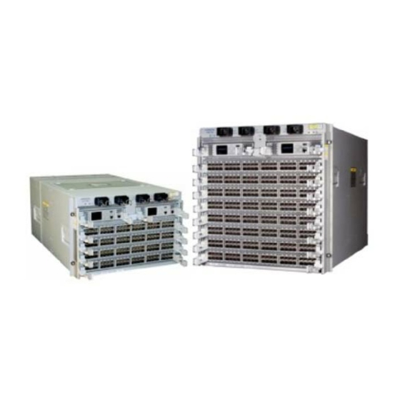
Quick Start Guide 7500 Series Modular Data Center Switches DCS-7504 / 7504E DCS-7508 / 7508E Arista Networks www.arista.com PDOC-00015-09... - Page 2 © Copyright 2017 Arista Networks, Inc. The information contained herein is subject to change without notice. Arista Networks and the Arista logo are trademarks of Arista Networks, Inc in the United States and other countries. Other product or service names may be trademarks or service marks of others.
-
Page 3: Table Of Contents
Table of Contents Chapter 1 Overview......................1 Scope..............................1 Receiving and Inspecting the Equipment....................1 Installation Process..........................1 Safety Information........................... 2 Obtaining Technical Assistance......................2 Specifications............................3 Chapter 2 Preparation......................5 Site Selection ............................5 Tools and Parts Required for Installation....................6 Electrostatic Discharge (ESD) Precautions .................... - Page 4 Appendix B Parts List......................29 Two-Post Rack Mount Parts ......................... 29 Four-Post Rack Mount Parts......................... 30 Parts Used in All Rack Mount Configurations ..................30 B.3.1 Cables............................30 B.3.2 Equipment..........................31 B.3.3 Rack Mount Alternate Parts ..................... 31 Appendix C Front Panel ....................33 Appendix D Rear Panel .....................37 Appendix E...
-
Page 5: Chapter 1 Overview
Chapter 1 Overview Scope This guide is intended for properly trained service personnel and technicians who need to install the following Arista Networks Data Center Switches: • DCS-7504 / 7504E • DCS-7508 / 7508E Important! Only qualified personnel should install, service, or replace this equipment. -
Page 6: Safety Information
Son élimination finale de ce produit doit être traitée selon toutes les lois et règlements nationaux. Safety Information Refer to the Arista Networks document Safety Information and Translated Safety Warnings available at: http://www.arista.com/support/docs/eos Obtaining Technical Assistance Any customer, partner, reseller or distributor holding a valid Arista Service Contract can obtain technical support in any of the following ways: •... -
Page 7: Specifications
Chapter 1: Overview Specifications Specifications Table 1-1 lists the specifications of Arista Data Center switches covered by this guide. Table 1-2 lists power specifications of modular switch components. Table 1-1 Modular Switch Specifications DCS-7508 / DCS-7508E DCS-7504 / DCS-7504E Height 11U: 485 mm (19.1inches) - Page 8 Specifications Chapter 1: Overview Quick Start Guide: 7500 Series Modular Data Center Switches...
-
Page 9: Chapter 2 Preparation
Chapter 2 Preparation Site Selection The following criteria should be considered when selecting a site to install the switch: Floor Space: Install the switch in an area that provides adequate clearance for removing front and rear components. Figure 2-1 displays switch clearance requirements. 60 cm (24 in) 86 cm (34 in) 32 cm (13 in) -
Page 10: Tools And Parts Required For Installation
Tools and Parts Required for Installation Chapter 2: Preparation When mounting the switch in a partially filled rack, load the rack from bottom to top, with the heaviest equipment at the bottom. Load the switch at the bottom if it is the only item in the rack. •... -
Page 11: Electrostatic Discharge (Esd) Precautions
Chapter 2: Preparation Electrostatic Discharge (ESD) Precautions Electrostatic Discharge (ESD) Precautions Observe these guidelines to avoid ESD damage when installing or servicing the switch. • Assemble or disassemble equipment only in a static-free work area. • Use a conductive work surface (such as an anti-static mat) to dissipate static charge. •... - Page 12 Electrostatic Discharge (ESD) Precautions Chapter 2: Preparation Quick Start Guide: 7500 Series Modular Data Center Switches...
-
Page 13: Chapter 3 Rack Mounting The Switch
Chapter 3 Rack Mounting the Switch The accessory kit provides components for installing the switch in two-post and four-post racks. • Section 3.1 provides instructions for mounting the switch in a two-post rack. • Section 3.2 provides instructions for mounting the switch in a four-post rack. The rack mounting procedure is identical for all modular switches. -
Page 14: Inserting The Switch Into The Rack
Two-Post Rack Mount Chapter 3: Rack Mounting the Switch Center-mount brackets Figure 3-1: Attaching the Center-mount Brackets 3.1.2 Inserting the Switch into the Rack Step 1 Move the chassis to the rack using a mechanical lift (Figure 3-2). If modules are inserted in the chassis, use the lift carefully to avoid damaging any components. Step 2 Lift the chassis into the rack. -
Page 15: Four-Post Rack Mount
Chapter 3: Rack Mounting the Switch Four-Post Rack Mount Step 4 Attach the bracket flanges to the rack posts (Figure 3-3). Space the screws evenly along the flange. Figure 3-3: Attaching Flanges to the Rack Post After completing the two-post installation, proceed to Chapter Four-Post Rack Mount The switch is mounted onto a four-post rack by assembling a shelf into the rack, then placing the switch... - Page 16 Four-Post Rack Mount Chapter 3: Rack Mounting the Switch Front Rack Post M6 Cage Nut M6 Screw Front Bracket M6 Nut Shelf Support M6 Screw M6 Nut M6 Screw Figure 3-4: Left Front Post Assembly: Four Post Rack Mount Step 2 Repeat step 1 on the right front rack post, assembling the parts at the same vertical level as those on the left rack post.
- Page 17 Chapter 3: Rack Mounting the Switch Four-Post Rack Mount Rear Rack Post Front Rack Post Left Shelf Figure 3-6: Adjusting the Left Shelf Step 5 Lift the left shelf above the shelf supports installed on the left front and left rear rack posts (step 1 and step 3).
- Page 18 Four-Post Rack Mount Chapter 3: Rack Mounting the Switch Rear Left Rack Post Inset A Inset A Inset A Inset A Inset B Front Left Rack Post Inset B Figure 3-7: Seating the Left Shelf Step 6 Install the right shelf on the right front and right rear rack posts by repeating step 4 and step 5 to obtain the rack configuration shown in Figure 3-8.
-
Page 19: Inserting The Switch Into The Rack
Chapter 3: Rack Mounting the Switch Four-Post Rack Mount 3.2.2 Inserting the Switch into the Rack Step 1 Move the chassis to the rack using a mechanical lift (Figure 3-9). If modules are inserted in the chassis, use the lift carefully to avoid damaging any components. Step 2 Lift the chassis into the rack. - Page 20 Four-Post Rack Mount Chapter 3: Rack Mounting the Switch Quick Start Guide: 7500 Series Modular Data Center Switches...
-
Page 21: Chapter 4 Cabling The Switch
Chapter 4 Cabling the Switch Cabling the AC Power Supply 4.1.1 Grounding the Switch After mounting the switch into the rack, connect the switch to the data center ground. Figure 4-1 displays the location of the grounding pads located on both sides of the power input sockets. Grounding Pad Grounding Pad INPUT... -
Page 22: Connecting Power Cables To An Ac Power Supply
VAC, 50 or 60 Hz, and 20 A. • DCS-7504 / 7504E requires the connection of one power supply to an active live circuit. • DCS-7508 / 7508E requires the connection of at least two power supplies to active circuits. - Page 23 Chapter 4: Cabling the Switch Cabling the AC Power Supply • Non-Redundant Configuration: Provide power to any two of the four power inputs. • Redundant Power Supply Configuration: Provide power to all four power inputs. • Power down the Switch: Remove all power cords from the power input sockets. Each power supply includes a fan that maintains proper power supply temperature and cools the supervisor modules located below the power input sockets.
-
Page 24: Connecting Supervisor Cables
Connecting Supervisor Cables Chapter 4: Cabling the Switch Connecting Supervisor Cables Supervisor modules contain console, management, and USB ports. Figure 4-4 displays port locations on supervisors provided with 7508 / 7504 switches. USB Port Status Summary POWER SUPPLIES FABRIC MODULES FAN MODULES LINECARDS Console (Serial) Port... -
Page 25: Connecting Line Card Modules And Cables
Chapter 4: Cabling the Switch Connecting Line Card Modules and Cables Connecting Line Card Modules and Cables Install required SFP, SFP+, and QSFP+ optic modules in line card module ports (Figure 4-6). Figure 4-6: SFP or SFP+ ports Connect cables as required to line card module ports or fixed MPO ports. Supervisor and line card module ejectors on the front of the chassis assist with cable management. - Page 26 Connecting Line Card Modules and Cables Chapter 4: Cabling the Switch Quick Start Guide: 7500 Series Modular Data Center Switches...
-
Page 27: Chapter 5 Configuring The Switch
Chapter 5 Configuring the Switch Arista switches ship from the factory in Zero Touch Provisioning (ZTP) mode. ZTP configures the switch without user intervention by downloading a startup configuration file or a boot script from a location specified by a DHCP server. To manually configure a switch, ZTP is bypassed. The initial... - Page 28 When the management port IP address is configured, use this command to access the switch from a host, using the address configured in step 9: ssh admin@192.0.2.8 Refer to the Arista Networks User Manual for complete switch configuration information. Quick Start Guide: 7500 Series Modular Data Center Switches...
-
Page 29: Appendix A Status Indicators
Appendix A Status Indicators Supervisor Module While the front panel of each switch can house two supervisors, switch operations require only one. Supervisors display switch component status and contain Ethernet management and console ports. Appendix C displays the supervisor location on each switch. The supervisor style depends on the switch model. -
Page 30: Supervisor Indicators: 7508E / 7504E
Supervisor Module Appendix A: Status Indicators Table A-1 Supervisor Activity LED States: 7508 / 7504 LED Name LED State Supervisor State Status LED Module failed. Active LED Supervisor is not active. Active LED Green Supervisor is active and controlling the switch. Component Activity Status The Supervisor Status Summary Screen displays indicators for the power supplies, fabric module, fan modules and line cards. -
Page 31: Line Card Module Indicators
Appendix A: Status Indicators Line Card Module Indicators Component Activity Status LEDs LEDs located below the vents and left of the input ports display summary indicators for power supplies, fabric modules, fan modules, and line cards. Table A-4 interprets the states of these indicators. When error conditions are indicated, refer to LEDs on the specified modules to determine the condition’s source. -
Page 32: Fan And Fabric Status Indicators
Yellow Port is disabled in software. Fan and Fabric Status Indicators Fan and Fabric Status LEDs are on fan modules (DCS-7508) or fan-fabric modules (DCS-7504, DCS-7508E, and DCS-7504E). Appendix D displays the position of these LEDs on the rear of each switch. -
Page 33: Appendix B Parts List
Appendix B Parts List Each switch provides an accessory kit that contains parts that are required to install the switch. This appendix lists the installation parts contained in the switch accessory kit. Two-Post Rack Mount Parts Table B-1 Two-Post Rack Mount Parts Quantity Description Center-mount brackets. -
Page 34: Four-Post Rack Mount Parts
Four-Post Rack Mount Parts Appendix B: Parts List Four-Post Rack Mount Parts Table B-2 Four-Post Rack Mount Parts Quantity Description Front brackets. Shelf supports. Back brackets. Left shelf. Right shelf. M6X16 panhead Phillips screws. M6 Cage Hex Nuts. M6 Cage Nut Square Hole Racks. Shelf Supports (4) Left Shelf (1) Front Brackets (2) -
Page 35: Equipment
Appendix B: Parts List Parts Used in All Rack Mount Configurations Warning All provided power cables are for use only with Arista products. B.3.2 Equipment Table B-4 Installation Equipment Provided in Accessory Kit Quantity Description Adjustable Wrench. B.3.3 Rack Mount Alternate Parts These parts are supplied for threaded racks that do not use M6 screws. - Page 36 Parts Used in All Rack Mount Configurations Appendix B: Parts List Quick Start Guide: 7500 Series Modular Data Center Switches...
-
Page 37: Appendix C Front Panel
Appendix C Front Panel This appendix displays the front panel of all switches covered by this guide. DCS-7508 Front Panel (fully populated) Power Input Sockets Status Summary Status Summary POWER SUPPLIES POWER SUPPLIES Supervisor Modules FABRIC MODULES FABRIC MODULES FAN MODULES FAN MODULES LINECARDS LINECARDS... - Page 38 Appendix C: Front Panel DCS-7504 Front Panel (fully populated) Power Input Sockets Status Summary Status Summary POWER SUPPLIES POWER SUPPLIES Supervisor Modules FABRIC MODULES FABRIC MODULES FAN MODULES FAN MODULES LINECARDS LINECARDS Linecard Modules DCS-7508E Front Panel (fully populated) Power Input Sockets...
- Page 39 Appendix C: Front Panel DCS-7504E Front Panel (fully populated) Power Input Sockets Supervisor Modules Linecard Modules Quick Start Guide: 7500 Series Modular Data Center Switches...
- Page 40 Appendix C: Front Panel Quick Start Guide: 7500 Series Modular Data Center Switches...
-
Page 41: Appendix D Rear Panel
Appendix D Rear Panel This appendix displays the rear panel of all switches covered by this guide. DCS-7508 Rear Panel PWR-2900AC PWR-2900AC PWR-2900AC PWR-2900AC Power Supplies FAULT FAULT FAULT FAULT PS 1 PS 2 PS 3 PS 4 FAN 1 FAN 2 FAN 3 FAN 4... - Page 42 Appendix D: Rear Panel DCS-7504 Rear Panel PWR-75-2900AC PWR-75-2900AC PWR-75-2900AC PWR-75-2900AC Power Supplies FAULT FAULT FAULT FAULT FAN1 FAN2 FAN3 FAN4 FAN4 FAN6 FC 1 FC 2 FC 3 FC 4 FC 4 FC 6 FM-7504 FM-7504 FM-7504 FM-7504 FM-7504...
- Page 43 Appendix D: Rear Panel DCS-7504E Rear Panel PWR-75-2900AC PWR-75-2900AC PWR-75-2900AC PWR-75-2900AC Power Supplies FAULT FAULT FAULT FAULT FAN1 FAN2 FAN3 FAN4 FAN4 FAN6 FC 1 FC 2 FC 3 FC 4 FC 4 FC 6 FM-7504 FM-7504 FM-7504 FM-7504 FM-7504 FM-7504 Fan and Fabric Status LEDs...
- Page 44 Appendix D: Rear Panel Quick Start Guide: 7500 Series Modular Data Center Switches...
-
Page 45: Appendix E Line Cards
Appendix E Line Cards This appendix displays the line cards supported by modular switches covered by this guide. DCS-7548S-LC Status LED 10G Port LEDs DCS-7500E-36Q-LC Status LED 40G Port LEDs 10G Port LEDs DCS-7500E-72S-LC Status LED 10G Port LEDs MXP Port LEDs Quick Start Guide: 7500 Series Modular Data Center Switches... - Page 46 Appendix E: Line Cards DCS-7500E-48S-LC Status LED 10G Port LEDs DCS-7500E-12CM-LC Status LED MXP Port LEDs DCS-7500E-6C2-LC Status LED CFP2 Port LEDs DCS-7500E-12CQ-LC Status LED 40/100G Port LEDs DCS-7500E-6CFPX-LC Status LED STATUS Coherent 7500-6CFPX-LC 100G 100G Ports Quick Start Guide: 7500 Series Modular Data Center Switches...
Need help?
Do you have a question about the DCS-7504 and is the answer not in the manual?
Questions and answers