
Related Manuals for Arista DCS-7304


Summary of Contents for Arista DCS-7304
-
Page 1: Quick Start Guide
Quick Start Guide 7300 Series Modular Data Center Switches DCS-7304 DCS-7308 DCS-7316 DCS-7324 DCS-7328 Arista Networks www.arista.com PDOC-00040-10... - Page 2 © Copyright 2017 Arista Networks, Inc. The information contained herein is subject to change without notice. Arista Networks and the Arista logo are trademarks of Arista Networks, Inc in the United States and other countries. Other product or service names may be trademarks or service marks of others.
-
Page 3: Table Of Contents
Table of Contents Chapter 1 Overview......................1 Scope..............................1 Receiving and Inspecting the Equipment....................1 Installation Process..........................1 Safety Information........................... 2 Obtaining Technical Assistance......................2 Specifications............................2 Chapter 2 Preparation......................7 Site Selection ............................7 Tools Required for Installation ........................ 8 Electrostatic Discharge (ESD) Precautions .................... 9 Chapter 3 Rack Mounting the Switch ................11 Two-Post Rack Mount........................... - Page 4 Chapter 5 Connecting Serial and Management Cables ..........27 Connecting Supervisor Cables ......................27 Connecting Linecard Modules and Cables ................... 28 Chapter 6 Configuring the Switch ...................29 Appendix A Status Indicators...................31 Supervisor Module ..........................31 Line Card Module Indicators ......................... 32 Fan and Fabric Status Indicators ......................
-
Page 5: Chapter 1 Overview
Chapter 1 Overview Scope This guide is intended for properly trained service personnel and technicians who need to install the following Arista Networks Data Center Switches: • DCS-7304 • DCS-7308 • DCS-7316 • DCS-7324 • DCS-7328 Important! Only qualified personnel should install, service, or replace this equipment. -
Page 6: Safety Information
Appendix B provide instructions for handing fabric modules. Safety Information Refer to the Arista Networks document Safety Information and Translated Safety Warnings available at: http://www.arista.com/support/docs/eos Obtaining Technical Assistance Any customer, partner, reseller or distributor holding a valid Arista Service Contract can obtain technical support in any of the following ways: •... - Page 7 Chapter 1: Overview Specifications Table 1-1 7300 Modular Switch and Component Specifications DCS-7304/7324 DCS-7308/7328 DCS-7316 Weight Empty 36 kg (78 lbs) 50 kg (110 lbs) 81 kg (178 lbs) Fully Loaded 89 kg (196 lbs) 140 kg (309 lbs) 244 kg (536 lbs)
- Page 8 5009 W / 6600 W DCS-7320X-32C-LC line cards Table 1-3 lists 7300X Series switch components. Table 1-3 7300X Series Chassis Model Fabric Module Fan-only Module Fan Spare Line Card Power Supply DCS-7304 DCS-7304X-FM-F DCS-7304-S-FAN-F FAN-7002-F DCS-7300X-32Q-LC PWR-3K-AC-F (Forward) DCS-7300X-64S-LC PWR-2700-DC-F DCS-7300X-64T-LC DCS-7304...
- Page 9 AC and DC power supply unit (PSU) comparison of circuit, cabling, and airflow for the DCS-7304, DCS-7308, and DCS-7316. Table 1-5 AC/DC PSU comparison (Circuit, Cabling, and Airflow for DCS-7304, DCS-7308, and DCS-7316) Branch Required Cabling and Interconnect...
- Page 10 Specifications Chapter 1: Overview Quick Start Guide: 7300 Series Modular Data Center Switches...
-
Page 11: Chapter 2 Preparation
Chapter 2 Preparation Site Selection The following criteria should be considered when selecting a site to install the switch: Floor Space: Install the switch in an area that provides adequate clearance for removing front and rear components. Figure 2-1 displays switch clearance requirements. Figure 2-1: Switch Component Removal Footprint •... -
Page 12: Tools Required For Installation
Tools Required for Installation Chapter 2: Preparation • All front panel modules have the same color handles. • Rear panel modules must have different color handles than front panel modules. Orient the switch to assure that the air intake modules face the cool aisle. If the airflow direction is not compatible with the installation site, contact your sales representative to obtain modules that circulate air in the opposite direction. -
Page 13: Electrostatic Discharge (Esd) Precautions
Chapter 2: Preparation Electrostatic Discharge (ESD) Precautions Four-Post Conventional Rack • Screws or rack mounting nuts and bolts. • Screwdriver. Electrostatic Discharge (ESD) Precautions Observe these guidelines to avoid ESD damage when installing or servicing the switch. • Assemble or disassemble equipment only in a static-free work area. •... - Page 14 Electrostatic Discharge (ESD) Precautions Chapter 2: Preparation Quick Start Guide: 7300 Series Modular Data Center Switches...
-
Page 15: Chapter 3 Rack Mounting The Switch
The accessory kit includes the following two-post mounting parts: • 2 center-mount brackets • 16 (DCS-7304) or 20 (DCS-7308) M4x8 panhead Phillips screws 3.1.1 Attaching Mounting Brackets to the Chassis Step 1 Orient the switch chassis and the two center-mount brackets (Figure 3-1). - Page 16 Two-Post Rack Mount Chapter 3: Rack Mounting the Switch Figure 3-1: Attaching the Center-mount Brackets Figure 3-2: Lifting the Switch Chassis into the Two Post Rack Step 4 Attach the bracket flanges to the rack posts. Secure the switch to the rack with screws through each bracket hole.
-
Page 17: Four-Post Rack Mount
Chapter 3: Rack Mounting the Switch Four-Post Rack Mount Four-Post Rack Mount The switch is mounted onto a four-post rack by assembling a shelf into the rack, then attaching the switch on the shelf. The four-post rack mount instructions include these sections: •... -
Page 18: Mounting Ears
Four-Post Rack Mount Chapter 3: Rack Mounting the Switch Figure 3-4: Right Shelf – Outer View 3.2.1.2 Mounting Ears Figure 3-5 displays the mounting ears, which secure the switch top to the rack. The two mounting ears are identical and installed above each shelf. The inner side of each ear may include a latch to the locking mechanism that secures the ear to the rack. -
Page 19: Switch Mounting Process
Chapter 3: Rack Mounting the Switch Four-Post Rack Mount Figure 3-6: Component Placement 3.2.3 Switch Mounting Process The switch mounting process consists of three steps: 1) installing the shelves; 2) installing the mounting ears; and 3) placing and securing the switch upon the shelves. 3.2.3.1 Shelf Installation The installation process for each shelf is identical. - Page 20 Four-Post Rack Mount Chapter 3: Rack Mounting the Switch Figure 3-7: Attaching the Right Shelf Step 3 Close the front locking mechanism latch (Figure 3-4). Step 4 Glide the slide-end to a position outside of its rear rack post (Figure 3-8).
-
Page 21: Mounting Ear Installation
Chapter 3: Rack Mounting the Switch Four-Post Rack Mount Figure 3-9: Seating the Left Shelf Step 6 Close the rear locking mechanism latch (Figure 3-4). 3.2.3.2 Mounting Ear Installation The mounting ears attach the top of the switch to the rack posts. Their placement on the posts depend on the switch model (Section 3.2.2). -
Page 22: Inserting The Switch Into The Rack
Four-Post Rack Mount Chapter 3: Rack Mounting the Switch 3.2.3.3 Inserting the Switch into the Rack Step 1 Rotate the stabilizer bar from the left shelf toward the right shelf such that the nob at the end of the stabilizer bar inserts into the notch at the rear of the ledge of the right shelf. Figure 3-11: Both Switch Shelves Installed Step 2 Move the chassis to the rack using a mechanical lift (Figure... -
Page 23: Chapter 4 Powering The Modular Switch
Table 4-1 Power Supply Capacity and Requirements for 7300 Series Modular Switches Switch Model Chassis Capacity Minimum Operating Requirements DCS-7304 / DCS-7324 Front Panel: 4 modules 1 active circuit DCS-7308 / DCS-7328 Front Panel: 6 modules... -
Page 24: Cabling The Ac Power Supply
Cabling the AC Power Supply Chapter 4: Powering the Modular Switch Cabling the AC Power Supply 4.1.1 Grounding the Switch After mounting the switch into the rack, connect the switch to the data center ground. Figure 4-1 displays the location of the grounding pads located on the front panel (left illustration) and rear panel (right illustration). -
Page 25: Cabling The Dc Power Supply
Chapter 4: Powering the Modular Switch Cabling the DC Power Supply Important! The retaining clip is optional (if provided). Step 2 Plug the power cables into the sockets. Step 3 Adjust the retaining clips if needed for your power cords (if retaining clip was provided). Step 4 Push the retaining clip back down over the cable (if retaining clip was provided). -
Page 26: Dc Power Adapter Installation
Cabling the DC Power Supply Chapter 4: Powering the Modular Switch 4.2.1 DC Power Adapter Installation Before you begin, refer to the Arista Networks document Safety Information and Translated Safety Warnings available at: http://www.arista.com/support/product-documentation. Preparation Before performing any installation actions, ensure power is removed from DC circuits by turning off the power line servicing the circuits. - Page 27 Chapter 4: Powering the Modular Switch Cabling the DC Power Supply Step 2 Remove the Flange locking nuts from each of the terminal studs. Figure 4-6: Remove the Flange locking nuts from each terminal stud Step 3 Secure each power cable lug to the terminal studs with the Flange locking nuts. •...
- Page 28 Cabling the DC Power Supply Chapter 4: Powering the Modular Switch Figure 4-9: Slide the clear plastic cover over the terminal studs until it clicks into place. Step 4 Slide the cover over the terminal studs until it clicks into place. Figure 4-10: Replace the plastic cover Quick Start Guide: 7300 Series Modular Data Center Switches...
- Page 29 Chapter 4: Powering the Modular Switch Cabling the DC Power Supply Figure 4-11: Insert the adapter into the power supply. Step 5 Tighten the two captive screws (on the bottom of the adapter) to the power supply module. Torque screws with #2 Posidriv to 2 N*m(17.7 in. lbs.) Step 6 Attach the power cable to the DC power source.
- Page 30 Cabling the DC Power Supply Chapter 4: Powering the Modular Switch Quick Start Guide: 7300 Series Modular Data Center Switches...
-
Page 31: Chapter 5 Connecting Serial And Management Cables
Chapter 5 Connecting Serial and Management Cables Connecting Supervisor Cables Supervisor modules contain console, management, and USB ports. Figure 5-1 displays port locations on 7300 Series Modular switch supervisors. Figure 5-1: Supervisor Ports • Console (Serial) Port: Connect to a PC with RJ-45 to DB-9 serial adapter cable. Default switch settings include: •... -
Page 32: Connecting Linecard Modules And Cables
Connecting Linecard Modules and Cables Chapter 5: Connecting Serial and Management Cables Connecting Linecard Modules and Cables Install required SFP, SFP+, and QSFP+ optic modules in linecard module ports (Figure 5-2). Connect cables as required to linecard module ports or RJ45 ports. Figure 5-2: SFP or SFP+ ports Caution Excessive bending can damage interface cables, especially optical cables. -
Page 33: Chapter 6 Configuring The Switch
Chapter 6 Configuring the Switch Arista switches ship from the factory in Zero Touch Provisioning (ZTP) mode. ZTP configures the switch without user intervention by downloading a startup configuration file or a boot script from a location specified by a DHCP server. To manually configure a switch, ZTP is bypassed. The initial configuration... - Page 34 When the management port IP address is configured, use this command to access the switch from a host, using the address configured in step 9: ssh admin@192.0.2.8 Refer to the Arista Networks User Manual for complete switch configuration information. Quick Start Guide: 7300 Series Modular Data Center Switches...
-
Page 35: Appendix A Status Indicators
Appendix A Status Indicators Supervisor Module While the front panel of each switch can house two supervisors, switch operations require only one. Supervisors display switch component status and contain Ethernet management and console ports. Appendix B displays the supervisor location on each switch. The supervisor provides one serial console port, two Ethernet management ports, two USB ports, and one clock input port. -
Page 36: Line Card Module Indicators
Line Card Module Indicators Appendix A: Status Indicators Component Activity Status LEDs LEDs located below the vents and left of the input ports display summary indicators for power supplies, fabric modules, fan modules, and line cards. Table A-2 interprets the states of these indicators. When error conditions are indicated, refer to LEDs on the specified modules to determine the condition’s source. -
Page 37: Fan And Fabric Status Indicators
Figure A-3 on page 34 displays a DCS-7304-FM fabric module and the fan modules that it contains. Fan and fabric module indicators are displayed in Figure A-3 on page 34. -
Page 38: Power Supply Status Indicators
Power Supply Status Indicators Appendix A: Status Indicators Figure A-3: Fan Status and Fabric Status LEDs The fan module installation indicator is green when the fan module is properly installed or red when the module is not fully installed. Table A-6 interprets the states of the Fan and Fabric Status LEDs. - Page 39 Appendix A: Status Indicators Power Supply Status Indicators Figure A-4: Power Supply Table A-7 interprets the states of the Power Supply Status LED. Table A-7 Power Supply Status AC OK LED Fault LED DC OK LED Status Green Green Power Supply module operating normally. Green AC is present, Main output is off.
- Page 40 Power Supply Status Indicators Appendix A: Status Indicators Quick Start Guide: 7300 Series Modular Data Center Switches...
-
Page 41: Appendix B Fabric And Fan-Only Module Handling
Appendix B Fabric and Fan-only Module Handling Fabric and Fan-only Module Description Each switch has four rear slots for fabric modules. In addition to providing the data transport media, fabric modules contain fan modules that circulate air through the switch. Proper switch operation requires the population of each rear slot. -
Page 42: Handling Fabric Modules
These sections describe fabric module handling procedures. Illustrations depict a DCS-7316 chassis and fabric modules. While proper handling of DCS-7316 components is imperative because of their size and weight, the instructions also describe best practices for handling DCS-7304 and DCS-7308 components. -
Page 43: Inserting Fabric Modules
Appendix B: Fabric and Fan-only Module Handling Handling Fabric Modules Step 5 Grasp the module frame and pull the module until it is completely outside of the chassis. Figure B-3: Fabric Module Removal: Initial Position and Opening the Lock-Levers Figure B-4: Fabric Module Removal: Edging the Module Out and Closing the Lock-Levers The DCS-7316 fabric module is almost three feet long and weighs close to 40 pounds. -
Page 44: Handling Fan-Only Modules
Appendix B: Fabric and Fan-only Module Handling Handling Fan-only Modules Figure B-5-left depicts a DCS-7304 chassis with installed fabric modules (slots 1 and 2) and fan-only modules (slots 3 and 4). Lock-levers are shown in the open (slot 3) and closed (slot 4) position Figure B-5-right displays the position of the lock lever release screw (below the extended handles). -
Page 45: Appendix C Parts List
Terminal Block, M4 Lug RJ-45 Patch Panel Cables, 2 meters. RJ-45 to DB9 Adapter Cable, 2 meters. Warning All provided power cables are for use only with Arista products. Figure C-1: DC Adapter Quick Start Guide: 7300 Series Modular Data Center Switches... -
Page 46: Four-Post Rack Mount Parts
Left shelf. Right shelf. Figure C-2: Four-Post Rack Mount Parts Two-Post Rack Mount Parts Two-post rack mount parts for DCS-7304 and DCS-7308 switches are available through your sales representative. Two-post rack mounts are not supported for DCS-7316 switches. Quantity Description Center-mount brackets. - Page 47 Appendix C: Parts List Two-Post Rack Mount Parts Figure C-3: Two-Post Rack Mount Parts Quick Start Guide: 7300 Series Modular Data Center Switches...
- Page 48 Two-Post Rack Mount Parts Appendix C: Parts List Quick Start Guide: 7300 Series Modular Data Center Switches...
-
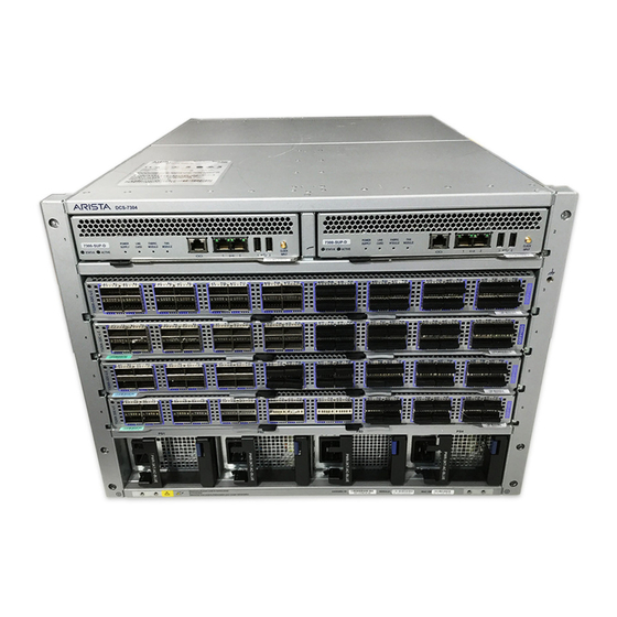
Page 49: Appendix D Front Panels
Appendix D Front Panels This appendix displays the front panel of all switches covered by this guide. DCS-7304 and DCS-7324 Front Panel (fully populated) Quick Start Guide: 7300 Series Modular Data Center Switches... - Page 50 Appendix D: Front Panels DCS-7308 and DCS-7328 Front Panel (fully populated) Quick Start Guide: 7300 Series Modular Data Center Switches...
- Page 51 Appendix D: Front Panels DCS-7316 Front Panel (fully populated) Quick Start Guide: 7300 Series Modular Data Center Switches...
- Page 52 Appendix D: Front Panels Quick Start Guide: 7300 Series Modular Data Center Switches...
-
Page 53: Appendix E Rear Panels
Appendix E Rear Panels This appendix displays the rear panel of all switches covered by this guide. DCS-7304 and DCS-7324 Rear Panel Quick Start Guide: 7300 Series Modular Data Center Switches... - Page 54 Appendix E: Rear Panels DCS-7308 and DCS-7328 Rear Panel Quick Start Guide: 7300 Series Modular Data Center Switches...
- Page 55 Appendix E: Rear Panels DCS-7316 Rear Panel Quick Start Guide: 7300 Series Modular Data Center Switches...
- Page 56 Appendix E: Rear Panels Quick Start Guide: 7300 Series Modular Data Center Switches...
-
Page 57: Appendix F Line Cards
Appendix F Line Cards This appendix displays the Line cards supported by modular switches covered by this guide. DCS-7300X-32Q-LC DCS-7300X-64S-LC DCS-7300X-64T-LC Quick Start Guide: 7300 Series Modular Data Center Switches... - Page 58 Appendix F: Line Cards DCS-7320X-32C-LC Quick Start Guide: 7300 Series Modular Data Center Switches...
Need help?
Do you have a question about the DCS-7304 and is the answer not in the manual?
Questions and answers