
Related Manuals for Arista 7368X Series


Summary of Contents for Arista 7368X Series
- Page 1 Quick Start Guide 7368X Series Modular Data Center Switches Arista Networks www.arista.com PDOC-00150-01...
- Page 2 © Copyright 2019 Arista Networks, Inc. The information contained herein is subject to change without notice. Arista Networks and the Arista logo are trademarks of Arista Networks, Inc in the United States and other countries. Other product or service names may be trademarks or service marks of others.
-
Page 3: Table Of Contents
Configuring the Switch ...................19 Appendix A Status Indicators...................21 Supervisor Module ..........................21 Line Card Module Indicators ......................... 22 Fan Module Status Indicators ....................... 23 Power Supply Status Indicators ......................24 Appendix B Parts List......................25 Quick Start Guide: 7368x Series Modular Data Center Switches... - Page 4 Installing Supervisor Module....................37 Linecards .............................. 37 F.5.1 Removing Linecard ........................37 F.5.2 Installing Linecard ........................37 Optical Transceivers ..........................38 Appendix G Regulatory Model Numbers .................39 Appendix H Taiwan RoHS Information ................41 Quick Start Guide: 7368x Series Modular Data Center Switches...
-
Page 5: Chapter 1 Overview
Step 3 Attach the mounting brackets and install the switch in an equipment rack (Chapter Step 4 Connect the switch to the power source and network devices (Chapter 4 Chapter Step 5 Configure the switch (Chapter Quick Start Guide: 7368x Series Modular Data Center Switches... -
Page 6: Safety Information
Appendix F provides instructions for handing fabric modules. Safety Information Refer to the Arista Networks document Safety Information and Translated Safety Warnings available at: https://www.arista.com/en/support/product-documentation Obtaining Technical Assistance Any customer, partner, reseller or distributor holding a valid Arista Service Contract can obtain technical support in any of the following ways: •... -
Page 7: Specifications
Chapter 1: Overview Specifications Specifications Table 1-1 lists specifications of Arista Data Center modular switches and components covered by this guide. Table 1-1 7368 Modular Switch and Component Specifications DCS-7368X4 Height 4 RU: 179 mm (7.0 inches) Width 442 mm (17.4 inches) - Page 8 Full chassis loaded with 961 W / 1998 W 1x DCS-7368-SUP-D supervisor 1x DCS-7368X4-SC switch card 8x DCS-7368-16C-LC line cards 5x Fans 2x PWR-1900-AC power supplies (1): Excluding optics. (2): With 4.5 W optics. Quick Start Guide: 7368x Series Modular Data Center Switches...
-
Page 9: Chapter 2 Preparation
Airflow Orientation: Determine airflow direction of the fan modules and power supply modules. Fan and power supply module handles indicate airflow direction. Note All power supplies may not be supported by the switch configuration you have. Quick Start Guide: 7368x Series Modular Data Center Switches... -
Page 10: Tools Required For Installation
In addition to the accessory kit, the following tools are required to install a modular switch: All Racks • Mechanical device capable of lifting chassis being installed (chassis weight listed in Table 1-1 on page Four-Post Tool-less Rack No additional equipment required. Quick Start Guide: 7368x Series Modular Data Center Switches... -
Page 11: Electrostatic Discharge (Esd) Precautions
Keep replacement parts in their original static-free packaging. • Remove all plastic, foam, vinyl, paper, and other static-generating materials from the work area. • Use tools that do not create ESD. Quick Start Guide: 7368x Series Modular Data Center Switches... - Page 12 Electrostatic Discharge (ESD) Precautions Chapter 2: Preparation Quick Start Guide: 7368x Series Modular Data Center Switches...
-
Page 13: Chapter 3 Rack Mounting The Switch
Rack mounting ears Follow the steps listed below to attach the shelves to the rack. Step 1 Extend the sliding end of each shelf so that it can be placed on the rack. Quick Start Guide: 7368x Series Modular Data Center Switches... - Page 14 You must ensure that the shelves are installed at the same level in the rack. Figure 3-2: Adjusting Shelves to Fit onto the Rack (Right Shelf Shown) The installed switch shelves are shown in Figure 3-3. Quick Start Guide: 7368x Series Modular Data Center Switches...
-
Page 15: Mounting Ears Installation
Use a forklift to raise and align the switch with the installed shelves and insert the rollers on the rack mount ears into the shelves' channels. Push and slide the switch into the rack to secure. Quick Start Guide: 7368x Series Modular Data Center Switches... - Page 16 The rack mounting ears use only the top two rack units but you must allocate four rack units from the top of the shelves for the switch. Figure 3-5: Inserting the Switch Figure 3-6: Securing the Switch After completing the Four-Post Installation, proceed to Chapter Quick Start Guide: 7368x Series Modular Data Center Switches...
-
Page 17: Chapter 4 Powering The Modular Switch
Important! This equipment must be grounded. Never defeat the ground conductor. This unit requires over-current protection. Cet équipement doit être mis à la terre. Ne jamais modifier le conducteur de terre. Cet appareil nécessite de protection contre les surintensités. Quick Start Guide: 7368x Series Modular Data Center Switches... -
Page 18: Cabling The Ac Power Supply
After the switch is grounded, ESD wrist straps can be grounded by connecting them to the ESD port on either the rear (Figure 4-2) or the front of the switch (Figure 4-3). Figure 4-2: Grounding Pad and ESD Grounding Pad Sockets (Rear) Quick Start Guide: 7368x Series Modular Data Center Switches... -
Page 19: Connecting Power Cables To An Ac Power Supply
The power supplies require power cables that comply with IEC-320 C19 plug. The accessory kit provides 14 AWG, C19 to C20 power cables. To insert a power cable: Step 1 Pull the retaining clip back on each power input socket. Quick Start Guide: 7368x Series Modular Data Center Switches... - Page 20 Step 3 Adjust the retaining clips if needed for your power cords (if retaining clip was provided). Step 4 Push the retaining clip back down over the cable (if retaining clip was provided). Quick Start Guide: 7368x Series Modular Data Center Switches...
-
Page 21: Chapter 5 Connecting Serial And Management Cables
8 data bits • Ethernet management port: Connect to 10/100/1000 management network with RJ-45 cable. • Ethernet management port (optical): Connect to 1 Gbit management network with SFP connector module and cable. Quick Start Guide: 7368x Series Modular Data Center Switches... -
Page 22: Connecting Linecard Modules And Cables
In some devices, adjacent QSFP ports may require you to rotate the module for insertion. Figure 5-3: Optical Module Insertion Note For more information about supported optical transceivers, refer to https://www.arista.com/assets/data/pdf/Transceiver-Guide-V04.pdf. Caution Excessive bending can damage interface cables, especially optical cables. Quick Start Guide: 7368x Series Modular Data Center Switches... -
Page 23: Chapter 6 Configuring The Switch
Chapter 6 Configuring the Switch Arista switches ship from the factory in Zero Touch Provisioning (ZTP) mode. ZTP configures the switch without user intervention by downloading a startup configuration file or a boot script from a location specified by a DHCP server. To manually configure a switch, ZTP is bypassed. The initial configuration... - Page 24 When the management port IP address is configured, use this command to access the switch from a host, using the address configured in step 9: ssh admin@192.0.2.8 Refer to the Arista Networks User Manual for complete switch configuration information. Quick Start Guide: 7368x Series Modular Data Center Switches...
-
Page 25: Appendix A Status Indicators
LEDs on the specified components to determine the condition’s source. Table A-1 Supervisor LED States LED Name LED State Module State Power Supply Green All powered modules are operating normally. At least one module has failed. Quick Start Guide: 7368x Series Modular Data Center Switches... -
Page 26: Line Card Module Indicators
Port LEDs on the DCS-7368-16C-LC line card. Arrows indicate the port status being displayed by the corresponding port status LED. Figure A-2: Linecard Status LEDs (DCS-7368-16C-LC) Linecard Port LEDs Linecard Status LED Linecard Ejector Latch Quick Start Guide: 7368x Series Modular Data Center Switches... -
Page 27: Fan Module Status Indicators
Fan Status LED. Table A-4 Fan and Fabric Status LED States LED State Status The module is inserted but not receiving power – it may not be properly seated. Quick Start Guide: 7368x Series Modular Data Center Switches... -
Page 28: Power Supply Status Indicators
No AC power to the module. Module has faulted. Blinking Green PSU has AC power but hasn't been enabled by the system - indicates that either the power supply or the Switch Module isn't fully inserted. Quick Start Guide: 7368x Series Modular Data Center Switches... -
Page 29: Appendix B Parts List
Power cables: 14 AWG, C19-C20 supplied with switch RJ-45 Patch Panel Cables, 2 meters. RJ-45 to DB9 Adapter Cable, 2 meters. Warning All provided power cables are for use only with Arista products. Four-Post Rack Mount Parts Quantity Description Mounting Ears Left shelf. - Page 30 Four-Post Rack Mount Parts Appendix B: Parts List Figure B-1: Four-Post Rack Mount Parts Left Shelf Right Shelf Quick Start Guide: 7368x Series Modular Data Center Switches...
-
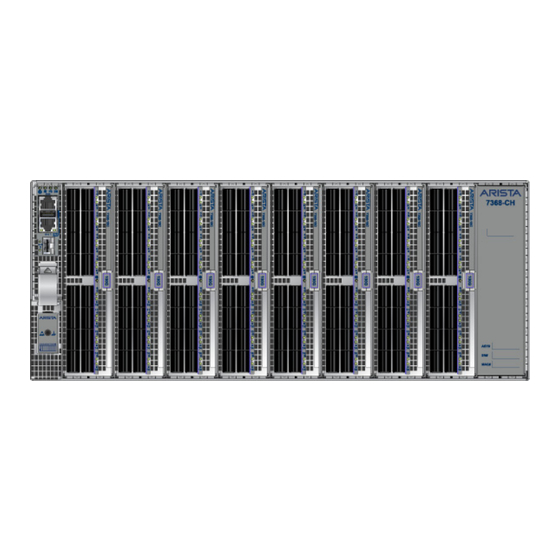
Page 31: Appendix C Front Panels
Appendix C Front Panels This appendix displays the front panel of all switches covered by this guide. DCS-7368X4 Front Panel (fully populated) Supervisor Module Supervisor Ejector Latch Linecard Ejector Latch Quick Start Guide: 7368x Series Modular Data Center Switches... - Page 32 Appendix C: Front Panels Quick Start Guide: 7368x Series Modular Data Center Switches...
-
Page 33: Appendix D Rear Panels
This appendix displays the rear panel of all switches covered by this guide. DCS-7368X4 Rear Panel Switch Card Module Release Handle Fan Module Release Lever Fan Installation Indicator Fan Status LED PSU Status LED PSU Release Handle Ground Quick Start Guide: 7368x Series Modular Data Center Switches... - Page 34 Appendix D: Rear Panels Quick Start Guide: 7368x Series Modular Data Center Switches...
-
Page 35: Appendix E Line Cards
Appendix E Line Cards This appendix displays the Line cards supported by modular switches covered by this guide. DCS-7368-16C-LC Linecard Port LEDs Linecard Status LED Linecard Ejector Latch Quick Start Guide: 7368x Series Modular Data Center Switches... - Page 36 Appendix E: Line Cards Quick Start Guide: 7368x Series Modular Data Center Switches...
-
Page 37: Appendix F Maintenance And Field Replacement
Step 3 Pinch the release levers towards the center to unlock the module from the chassis. Step 4 Carefully, remove the switch card module from the chassis while supporting it through the process. Quick Start Guide: 7368x Series Modular Data Center Switches... -
Page 38: Inserting Switch Card Module
Step 2 Power down the power supply to be removed by disconnecting the AC power cable. Step 3 Push the power supply release handle and remove the power supply (Figure F-2). Figure F-2: Remove power supply Quick Start Guide: 7368x Series Modular Data Center Switches... -
Page 39: Installing A Power Supply
Step 1 Ground yourself with an ESD wrist strap. Step 2 Push the fan module release lever and slide the fan module out of the switch (Figure F-3). Figure F-3: Removing fan module Quick Start Guide: 7368x Series Modular Data Center Switches... -
Page 40: Installing A Fan Module
Step 1 Put on a grounded ESD strap. Step 2 Lift the supervisor module ejector latch and move the latch down to release the supervisor module. Step 3 Gently remove the supervisor module by pulling outwards. Quick Start Guide: 7368x Series Modular Data Center Switches... -
Page 41: Installing Supervisor Module
Step 1 Put on a grounded, anti-static ESD strap. Step 2 Unpack the linecard to be installed. Step 3 Slide the linecard gently into the slot. Quick Start Guide: 7368x Series Modular Data Center Switches... -
Page 42: Optical Transceivers
Step 5 Verify that the linecard is operating normally (Table A-3 on page 23). Optical Transceivers For more information about supported optical transceivers and how to remove or install them, refer to https://www.arista.com/assets/data/pdf/Transceiver-Guide-V04.pdf. Quick Start Guide: 7368x Series Modular Data Center Switches... -
Page 43: Appendix G Regulatory Model Numbers
This appendix lists the regulatory model numbers (RMNs), where applicable, for the product models for the switches described in this document. Table G-1 Regulatory Model Numbers and Product Numbers Regulatory Model Number (RMN) Product Number(s) AN1722 DCS-7368X4 Quick Start Guide: 7368x Series Modular Data Center Switches... - Page 44 Appendix G: Regulatory Model Numbers Quick Start Guide: 7368x Series Modular Data Center Switches...
-
Page 45: Appendix H Taiwan Rohs Information
Appendix H Taiwan RoHS Information This appendix provides Taiwan RoHS information for switches covered by this guide. For Taiwan BSMI RoHS Table, go to https://www.arista.com/assets/data/pdf/AristaBSMIRoHS.pdf. Quick Start Guide: 7368x Series Modular Data Center Switches... - Page 46 Appendix H: Taiwan RoHS Information Quick Start Guide: 7368x Series Modular Data Center Switches...
Need help?
Do you have a question about the 7368X Series and is the answer not in the manual?
Questions and answers