Telguard TG-1 Express Installation Manual
Hide thumbs
Also See for TG-1 Express:
- Installation and operating instructions manual (26 pages) ,
- Quick install manual (13 pages) ,
- Quick install manual (2 pages)

Related Manuals for Telguard TG-1 Express


Summary of Contents for Telguard TG-1 Express
- Page 1 COMPANY CONFIDENTIAL ® For use by TELGUARD customers only. Distribution to other parties strictly prohibited. April 20, 2016 56049201...
-
Page 2: Important Note
The Telguard model TG-1 Express (p/n TG1LAX01) cellular alarm communicator is UL Listed for Household Fire systems and Household Burglary systems. This means that the TG-1 Express may be used in Household Burglary systems, Household Fire systems or combined Household Burglary &... -
Page 3: About This Manual
This is the exclusive warranty and no other warranties will be honored, whether expressed or implied. If a Telguard unit needs to be returned for repair, please return the product to the distributor that the unit was originally purchased from. If you are unsure of the distributor, please contact the Telguard RMA Department at 800-229-2326 option 1 to provide the distributor who sold the unit. - Page 4 An RMA must be assigned before returning product. You may obtain an RMA via phone at 800-229-2326 option 1, or via email at returns@telguard.com. The RMA number assigned must be on outside of box or product will not be accepted for return.
- Page 5 Terms and Conditions for Use of Telguard Product These Terms and Conditions are a legal contract between you and Telguard for the title to and use of the Product. BY RETAINING AND USING THE PRODUCT YOU AGREE TO THE TERMS AND CONDITIONS INCLUDING WARRANTY DISCLAIMERS, LIMITATIONS OF LIABILITY AND INDEMNIFICATION PROVISIONS BELOW.
- Page 6 WARRANTY and LIMITATIONS TELGUARD WILL REPAIR OR REPLACE (OUR OPTION) INOPERATIVE UNITS FOR UP TO TWO YEARS FROM DATE OF MANUFACTURE. EXCLUDES DAMAGE DUE TO LIGHTNING OR INSTALLER ERROR AS WELL AS UNITS THAT INCORPORATE MATERIAL, OR USED IN A MANNER OR ENVIRONMENT, NOT SPECIFICALLY AUTHORIZED IN THIS MANUAL.
-
Page 7: Table Of Contents
Table of Contents Important Note Foreword Table of Contents General Description and Operation Visual Tour TG-1 Express – First Look Features Operating Mode Panel-Supplied Power Single Line Interface Cable (SLIC) Multiple Alarm Format Support Complete Supervision of Communication Path Telguard Automatic Self-test Report... - Page 8 Pre-Installation Checklist Installation Summary Step 1: Register the Telguard Unit for Service Step 2: Locate Unit and Measure Signal Strength (RSSI) Step 3: Activate & Transmit Alarms Step 4: Connect the Supervisory Trip Outputs Step 5: Connect and Test the Trip Input (optional) Step 6: Complete the Telguard Unit Installation Appendix 1 –...
-
Page 9: General Description And Operation
(cellular) for Household alarm panels. When transmitting an alarm signal, the Telguard unit obtains its data from the alarm panel by way of a telephone interface. The Telguard will obtain all alarm signal information including monitoring station phone number, account number and all zones for every alarm transmission. -
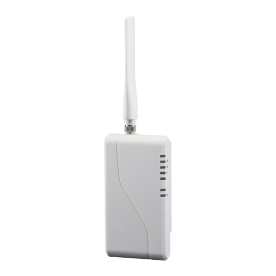
Page 10: Visual Tour
Visual Tour TG-1 Express – First Look Reset Pinho le Butt on RSSI Butt on LED In dicato rs Recessed Cab le Access 56049201 © 2016 Telguard... - Page 11 Inside the TG-1 Express 56049201 © 2016 Telguard...
-
Page 12: Features
Express is about the same as what is used by many keypads. Simply connect the Auxiliary power output from any voltage compatible (6 – 16 VDC) panel to the DC input on the TG-1 Express. Using the panel to provide power for the TG-1 Express allows for a simpler installation, and eliminates the need for additional A/C outlets. -
Page 13: Complete Supervision Of Communication Path
If the alarm format is changed for whatever reason, the Telguard will sense the new format and accept the alarm signal. In order for the host alarm panel to be compatible with the Telguard, the panel must be programmed to transmit alarm messages to the central station using one of the following non-extended formats: ... - Page 14 Radio Failure Condition (RFC) Radio communications failure condition (RFC) is declared when the Telguard TG-1 Express is unable to transmit over the cellular network even with acceptable signal strength. RFC is indicated by the STC LED flashing 5 times. RFC is cleared when communication with the TCC is restored.
-
Page 15: Telguard Automatic Self-Test Report
Telguard TG-1 Express when it processes the automatic self-test signal. This data contains current operational status (C.O.S.) of the Telguard TG-1 Express such as "All OK", current trip input status, or any combination of the system trouble conditions, as well as the current signal strength. -
Page 16: Programmable Supervisory Trip Output (Stc) Relays
Trips on transmit-disable command from the Communication Center. This radio command disables only the Telguard transmitter and would be used, for example, to shut down the Telguard due to a runaway panel dialer. Diagnostic and Status LEDs Eight LEDs are provided as a useful aid during installation and give installers an immediate visual indication of system status. -
Page 17: Complete Factory Reset Option
Complete Factory Reset Option A special function within the Telguard TG-1 Express allows you to perform a complete Factory Reset on the unit. This reset will change all unit settings back to a defaulted configuration. To begin the factory reset, wait for the unit to initialize and hold down the RSSI button for 15 seconds. -
Page 18: Getting Ready
Getting Ready The Telguard TG-1 Express can only be activated when all the necessary accounting information has been entered into the customer database located at the Telguard Communication Center. The database includes information about the customer account, unit location, and system test plan information. - Page 19 Note: Your unit may be subject to airtime charges for unintended use. Telguard Cellular Service offers several cellular service rate plans. 56049201 © 2016 Telguard...
-
Page 20: Installation
Installation Summary There are six steps in installing Telguard properly. IF YOU DO NOT PROCEED IN THE ORDER AND MANNER PRESCRIBED, YOU MAY NOT COMPLETE THE INSTALLATION IN THE TIME ALLOCATED. These six steps are summarized below and then explained in detail in the remainder of this manual. - Page 21 There is a default event configured for each alarm format, so that if the Telguard is configured to send trip input events to the TCC, a default notification will be sent to the central station. If the Telguard is configured to report restorals, the contact closure will also be reported.
-
Page 22: Step 2: Locate Unit And Measure Signal Strength (Rssi)
Step 2: Locate Unit and Measure Signal Strength (RSSI) Locate Unit Pick a spot next to the alarm panel where you think the Telguard TG-1 Express will be mounted and place the unit down temporarily in that spot. Do not mount it permanently now, since it may need to be moved to receive a better cellular radio signal or a remote high-gain antenna may be necessary. - Page 23 Connect the other end of the cable to the RJ-45 jack on the Telguard TG-1 Express. Reconnect the alarm panel’s power supply and battery, and ensure that the PWR indicator (LED 8) on the Telguard TG-1 Express is illuminated. Recommended Wire Size...
- Page 24 LED 2 = off Good LED 5-3 = on, LED 2 = off 3½ LED 5-3 = on, LED 2 = flash Excellent LED 5-2 = on LED Function Table – View RSSI Mode (RSSI button) 56049201 © 2016 Telguard...
-
Page 25: Step 3: Activate & Transmit Alarms
If you require a higher gain antenna or a longer cable assembly please contact your Telguard Sales Representative at 800-229-2326, option 5. Telguard offers a variety of high quality low loss antenna cables as well as high gain antennas. - Page 26 6V. Connect Alarm Panel to Telguard Unit If the alarm panel and the Telguard TG-1 Express were not already connected in Step 2, plug the modular jack of the alarm panel to the RJ-45 jack on the Telguard unit.
-
Page 27: Step 4: Connect The Supervisory Trip Outputs
No Service Condition (NSC): Disconnect the antenna from the Telguard. Check to see that the STC LED #2 flashes 4 times in the programmed period of time (default is 60 seconds) indicating loss of cellular service. Reconnect the antenna and check to see that the 56049201 ©... -
Page 28: Step 5: Connect And Test The Trip Input (Optional)
TRIP IN terminal, and the other side to either the GND terminal or to the chassis ground on the Telguard TG-1 Express circuit board. Note that trip inputs are normally wired such that there is a 2.2kΩ resistor in parallel with the external relay, so that a tamper condition (i.e. - Page 29 Slide the enclosure onto these screws. 56049201 © 2016 Telguard...
-
Page 30: Appendix 1 - Connection Guide
Connect to external relay/sensor or to the panel for Home Control Flex. Connect to panel auxiliary power. Connect to panel auxiliary ground. Note: When HomeControl Flex is enabled on the TG-1 Express, STC2 and TRIPIN are repurposed for keyswitch arming. 56049201... - Page 31 Attaching the RJ-45 Cable The RJ-45 cable to the panel can be attached to the Telguard TG-1 Express either with the enclosure open or closed. Note that, as with other Telguard products, the RJ-45 cable to the panel as well as all other wiring should be routed through the rear cable opening to allow the plastic lid of the Telguard TG-1 Express to be closed properly.
- Page 32 Allows an external relay 5 TRIP IN External trip Trip input to trigger an alarm input signal Auxiliary 6 GND power and Provides primary power DC power input ground of to TG-1 Express 7 PWR alarm panel 56049201 © 2016 Telguard...
-
Page 33: Appendix 2 - Troubleshooting Guide
Appendix 2 – Troubleshooting Guide This section provides a summary of all LED indications and their meanings, as well as the expected behavior of the Telguard TG-1 Express under various exception conditions. LED Indicator Guide – Normal Operating Mode LED Symbol... - Page 34 LED Symbol Color Showing Indication TG-1 Express initializing with cellular Solid On network LED #6 Not used Solid On Trip input activated LED #7 Green Trip Input Trip input not active or restored Solid On Power connected to unit LED #8...
- Page 35 LED #1 and #4 Press RSSI button twice Activation Failed None flashing to clear fault. Telguard will send Telguard Remote Radio LED #5 Status data to Telguard Query activated by flashes during None customer service for (Status data) transmit Customer Service. review...
-
Page 36: Appendix 3 - Detailed Specifications
4,737,975; 4,868,519; 5,134,644. Digital Cellular Radio The Telguard TG-1 Express radio provides data connectivity on LTE networks. The Telguard TG-1 Express transceiver is FCC compliant, meeting all of the requirements of Part 15 and 27 testing. It is also compliant to the PTCRB requirements. -
Page 37: Appendix 4 - Parts List
Appendix 4 – Parts List Basic Hardware: Model TG-1 Express Model TG-1 Express (p/n: TG1LAX01) meets the (p/n: TG1LAX01) requirements for Household Burglary, Household Fire, and Combination Burglary/Fire installations. It has a plastic enclosure, and dipole antenna. General Accessories: CTXL-12 Kit with antenna &... - Page 38 Wirelessly Protected means that your customer’s security system communicates with the alarm monitoring center using a robust and secure Telguard cellular communicator instead of a traditional landline. Wireless protection is the most reliable form of security because the communication path isn’t susceptible to being cut or lost due to inclement weather.
Need help?
Do you have a question about the TG-1 Express and is the answer not in the manual?
Questions and answers