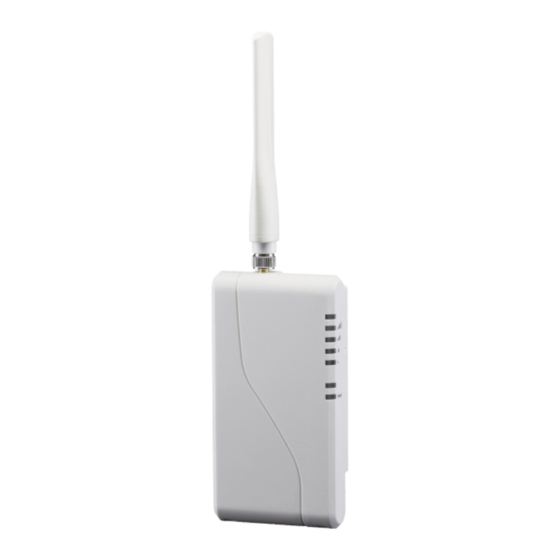
Telguard TG-1 Express Quick Install Manual
Hide thumbs
Also See for TG-1 Express:
- Installation manual (38 pages) ,
- Installation and operating instructions manual (26 pages) ,
- Quick install manual (13 pages)
Advertisement
Quick Links
Programming Codes
Mem
Field
Setting (default indicated in bold)
Loc.
Enter the SUM TOTAL of the events that you wish
STC Relay
to trip the STC relay by ADDING the
Output
corresponding values:
851
Reporting
00 = STC Relay Output Not Used
Normally
01 = LPF
Closed
16 = RFC
57 = ALL
1=30 seconds,
STC Trip
3=3 minutes
852
Delay for
5=20 minutes
NSC
7=45 minutes
9=24 hours
0 = terminate STC history display mode
858
STC History
1 = start STC history display mode
2 = clear STC history
PPF Delay
0 = disabled, 1 = 10 seconds, 2 = 20 seconds, ...
868
Timer
15 = 150 seconds
Trip Input
0 = no report
873
Reporting
1 = report trip
Trip Input
0 = no report
874
Restoral
1 = report restoral
Reporting
0 = swinger function disabled
Trip Input
875
Swinger
1 = swinger function enabled
Function
899
Factory Default Unit
To Program the TG-1 Express:
1.
After the TG-1 Express is initialized, connect a POTS phone to the RJ-45 jack
or lineman's butt set to the tip and ring turrets.
2.
Take the POTS phone off hook or put the butt set in talk mode. You should
hear dial tone.
3.
Dial ###*, and you should hear one beep.
4.
Dial #*, and you should hear one beep.
5.
Dial the POTS command number 8XX; you should hear one beep.
6.
Enter the command data; you should hear 2 beeps.
7.
After the last POTS command, dial * and listen for 2 beeps. Then hang up to
terminate the POTS programming session.
08 = NSC
32 = DTF
2=60 seconds
4=10 minutes
6=30 minutes
8=60 minutes
T
G
-
1
E
x
p
r
e
s
T
G
-
1
E
x
p
r
e
s
1
1
Register for Telguard Service
There are four ways to register the Telguard unit:
1. register online at www.telguardonline.com,
2. send the electronic registration form at www.telular.com/telguard,
3. email the completed registration form to cellservice@telular.com, or
4. fax the completed registration form to 678-945-1651.
2
2
Connect Dialer and Power to the TG-1 Express
Connect the alarm panel's dialer to the RJ-45 jack on the TG-1 Express.
If using the Single Line Interface Cable (SLIC) for power, connect the
RJ-45 cable's orange wire to the alarm panel's ground and its blue
wire to the panel's auxiliary power,. If using the terminal block,
connect pins 4 and 5 to the panel's ground and power.
s
Q
u
i
c
k
I
n
s
t
a
l
l
G
s
Q
u
i
c
k
I
n
s
t
a
l
l
G
Continued...
56042601
u
i
d
e
u
i
d
e
Advertisement

Related Manuals for Telguard TG-1 Express


Summary of Contents for Telguard TG-1 Express
- Page 1 To Program the TG-1 Express: Connect Dialer and Power to the TG-1 Express After the TG-1 Express is initialized, connect a POTS phone to the RJ-45 jack Connect the alarm panel’s dialer to the RJ-45 jack on the TG-1 Express.
- Page 2 By default, the relay will trip for any system trouble condition detected Radio receiving message sec) LED #5 on the TG-1 Express. Connect the relay output (pins 1 and 2 on the Green Radio Long Flash (2 terminal block) to a 24 hour zone on the alarm panel.
Need help?
Do you have a question about the TG-1 Express and is the answer not in the manual?
Questions and answers