Telguard TG-1 Express Quick Install Manual
Hide thumbs
Also See for TG-1 Express:
- Installation manual (38 pages) ,
- Installation and operating instructions manual (26 pages) ,
- Quick install manual (13 pages)
Advertisement
Quick Links
TG-1 Express Quick Install Guide
Pin
Description
STC2
Connect to 24-Hour N.C. Zone on panel for supervision.
STC1
Connect to 24-Hour N.O. Zone on panel for supervision
TRIPIN
Connect to external relay/sensor or to the panel for Home
Control Flex.
DC
Connect to panel auxiliary power.
GND
Connect to panel auxiliary ground.
56049302
All manuals and user guides at all-guides.com
1
portal www.telguard.com.
2
If using the Single Line Interface Cable (SLIC) for power, connect the
supplied RJ-45 cable's orange wire to the alarm panel's ground and its blue
wire to the panel's auxiliary power. If using the terminal block, connect pins
6 and 7 (labeled GND and DC) to the panel's ground and power,
respectively.
3
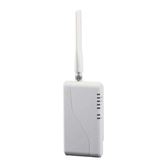
the side of the unit to put the LEDs into RSSI display mode. When you have
found a location that provides 2 bars or more (LEDs 4 and 5 solid) and more
than 1 cellular tower (LED 1 solid), install the mounting screws and attach
the TG-1 Express to the mounting screws. Press the RSSI button again to
return the LEDs to normal display mode.
4
Express. Note that the first alarm will activate the TG-1 Express with the
Telguard Communication Center, and will not be sent to the central station.
Register for Telguard Service
The registration form may be completed online through our 24/7 dealer
Connect Dialer and Power to the TG-1 Express
Connect the alarm panel's dialer to the RJ-45 jack on the TG-1 Express.
Connect the Antenna and Place the Unit
Connect the antenna to the antenna port, and press the RSSI button on
Activate the TG-1 Express
The last step is to trigger an alarm from the panel to activate the TG-1
Advertisement

Related Manuals for Telguard TG-1 Express


Summary of Contents for Telguard TG-1 Express
- Page 1 Connect Dialer and Power to the TG-1 Express Connect the alarm panel’s dialer to the RJ-45 jack on the TG-1 Express. If using the Single Line Interface Cable (SLIC) for power, connect the supplied RJ-45 cable’s orange wire to the alarm panel’s ground and its blue wire to the panel’s auxiliary power.
- Page 2 Unit is disabled or Activation Denied Flashing the TG-1 Express. Connect the STC2 relay output to a 24 Hour N.C. Zone on (if paired with LED 4) the alarm panel for supervision. Connect the STC1 relay output to a 24-Hour ALL OK N.O.
Need help?
Do you have a question about the TG-1 Express and is the answer not in the manual?
Questions and answers