Table of Contents
Advertisement
Quick Links
Advertisement
Table of Contents

Related Manuals for Alinco DR-735T/E


Summary of Contents for Alinco DR-735T/E
-
Page 1: Instruction Manual
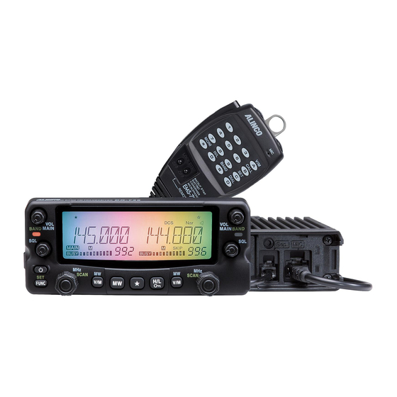
VHF/UHF TWIN BAND FM RADIO DR-735T/E Instruction Manual Thank you for purchasing your new Alinco radio. This Instruction manual contains important safety and operating instructions. Please read this manual carefully before using the product and keep it for future reference. - Page 2 Copyright © 2016 All right reserved. No part of this document may be reproduced, copied, translated or transcribed in any form or by any means without the prior written permission of Alinco. Inc., Osaka, Japan. English Edition Printed in Philippines.
- Page 3 To prevent any hazard during operation of Alinco’s radio product, in this manual and on the product you may find symbols shown below. Please read and understand the meanings of these symbols before starting to use the product. This symbol is intended to alert the user to an immediate...
- Page 4 WARNING Be sure to reduce the audio output level to minimum before using an earphone or a headset. Excessive audio may damage hearing. Do not open the unit without permission or instruction from the manufacturer. Unauthorized modification or repair may result in electric shock, fire and/or malfunction.
- Page 5 WARNING Do not open the unit and its accessories. Please consult with your local dealer of this product for service and assistance. Do not use the product in proximity to a audio products such as TV, radio and stereo. It may cause interference or receive interference. Do not install in a humid, dusty or insufficiently ventilated place.
- Page 6 Turn the power off immediately if the radio emits smoke or strange odors. Ensure the radio is safe, then bring it to the nearest Alinco service center. An operator’s license is required for this device. About hazardous materials used in this product.
- Page 10 Thank you very much for purchasing this excellent Alinco radio. Our products are ranked among the finest in the world. This radio has been manufactured with state of the art technology and it has been tested carefully at our factory. It is designed to operate to your satisfaction for many years under normal use.
- Page 11 The standard accessories may vary slightly depending on the version you have purchased. Please contact your local authorized Alinco dealer should you have any questions. Standard accessories may change without notice. Warranty Policy Please refer to any enclosed warranty information or contact your authorized Alinco dealer/distributor for the warranty policy before purchase.
- Page 12 Use a regulated power supply capable of providing continuous current of 12A or more. Power supplies that do not meet specifications may cause malfunction and/or damage to the radio and will void the warranty. Alinco offers excellent communication-grade power supplies as optional accessories. Please contact your local authorized Alinco dealer.
- Page 13 Initial Installation DC voltage range for operating this radio is DC 11.7V to 15.8V. Radio will not operate out of this range. Inspect cable and connection regularly to be IMPORTANT sure there is not any damage or burning. power supply lead Black DC power cable...
- Page 14 Initial Installation The main unit can be set with either side facing up. This can facilitate your ability to hear the speaker’s audio clearly. Position the front panel as you prefer. ① Slide the front panel toward right while pulling the tab toward you. ②...
- Page 15 <For making 4+/-0.2mm hole in globe box bottom> Car body Washer Tapping screw Mounting bracket Insert the supplied screws, nuts and washers through the mounting bracket and tighten. Adjust the angle to suit your favorite position. Alinco’s warranty does not include installation fee. NOTE...
- Page 16 There are 3 types of key operations; simply press, press after pressing [FUNC] key while FUNC appears on the display, or press and hold. Press] refers to press the key once and release the finger immediately. FUNC + this Key] refers to press the FUNC key once, then press another key while FUNC icon appears on the display.
- Page 17 Controls, Connectors, and Display Functions that requires press and holding to be activated Function Left band [VOL] knob Switches between VHF/Air-Band and UHF on the left band (P.19) Right band [VOL] Knob Switches between UHF/VHF and Air-Band on the right band (P.19) Left band dial Switches between VFO and memory scan on the left band.
- Page 18 Controls, Connectors, and Display ④ ① ② ⑤ ③ ⑥ Function Connects an external 8 speaker. Outputs audio of the right band. When External Speaker Jack 1 [SP1] another speaker is not connected to [SP2], left band audio is heard through internal speaker.
- Page 19 Controls, Connectors, and Display Function Appears when advanced set mode is available. (P.48) Appears during AM reception. (P.36) Appears during transmission when other band is set for mute. (P.52) Appears when APO function is activated. (P.49) Appears when setting the key lock. (P.62) Appears when [FUNC] key is pressed.
- Page 20 Controls, Connectors, and Display ② ① ③ ⑥ ④ ⑤ Function Increase the frequency, memory channel number, or setting value. DOWN Decrease the frequency, memory channel number, or setting value. Press the PTT (Push-To-Talk) key to transmit. Also press this key to set the MAIN PTT changes made by key operations.
- Page 21 Press and hold the PWR key until turns on. PWR key Repeat it until turns off. To avoid accidentally turn on/off, PWR key operation is designed to press and hold the key for 2 seconds. In this manual the MAIN band refers to the band which selected for VOL knob transmitting with MAIN icon on the display.
- Page 22 Basic Operations high high Adjust threshold level of the squelch. A squelch eliminates the background noise when a signal is not received. Turn the SQL knob clockwise until white-noise (the background SQL knob for SQL knob for noise when a signal is not received) and [BUSY] icon on the left band Right band display disappears.
-
Page 23: Changing Frequency By 1 Mhz Step
Basic Operations ial and VOL are potentiometers with push-switch built in, therefore compared to SQL, you may feel rattling on knobs but it’s not a defect. hen using UP/DOWN keys to change the frequency, a different tone of beep sounds to inform which direction the frequency is moving. When it NOTE passes the 500KHz order, another beeps sounds. - Page 24 Basic Operations DOWN direction UP direction 5.00 6.25 8.33 10.00 12.50 AUTO (5kHz) (6.25kHz) 15.00 100.00 50.00 30.00 25.00 20.00 Example: Change VHF tuning step on the both left and right bands from 20 KHz to 10 KHz. Press and hold VOL knob to set left and right bands to VHF.
- Page 25 Basic Operations After pressing the dial knob, rotating the dial will change the frequency by 1Mhz depending on which direction the dial is rotated (or if the UP/DOWN keys on microphone is pressed). Pressing the PTT key or any key except VOL and dial knob will complete the setting and the display will return to the original status.
- Page 26 Basic Operations By pressing V/M key while [FUNC] icon is on the display, programming will be completed and you will hear a beep sound. Be certain memory protect function in set mode is off to edit the memory IMPORTANT channels. One-touch programming is possible if you don’t care selecting specific memory channel Number.
- Page 27 Basic Operations emory channels have not been programmed, the unit will not be switched to the memory mode by pressing V/M key. ommon memory channels will recall by pressing V/M key on the left or right side, for Individual memory channels left V/M key will recall left NOTE individual memory channels and right V/M key will recall right individual memory channel.
- Page 28 Basic Operations Select memory mode and desired memory channel to copy to the VFO. Press VOL knob until hearing the beep sound. Press V/M key to switch to VFO mode. Select a frequency to be programmed in the VFO mode and set the parameters as appropriate.
- Page 29 Basic Operations You need to program at least one dual memory channel to perform this operation. Select the dual memory mode by pressing MW key. Press MW key to switch between VFO mode and dual memory mode (or memory mode and dual memory mode).
- Page 30 Basic Operations The memory channel stored in the common memory, individual memory, dual memory and program scan memory can be displayed with an alphanumeric tag instead of the default frequency display. There are 67 characters available including A-Z, 0-9. Select memory mode on the MAIN band and then select a channel to be programmed.
- Page 31 Basic Operations Some examples of available characters. More symbols and characters are available. The DR-735 has a total of 10 banks (01 to AL). 1000 memory channels other than dual memory channels are assigned into the desired banks for easy memory management. After programming common memory channels, press V/M key of desired side to select memory mode.
- Page 32 Basic Operations This is a memory mode that allows the radio to quickly recall the assigned memory channel by simply pressing a key, in VFO mode. The default setting is 145.00MHz/435.00MHz as E-model, 145.000MHz/445.000MHz as T-model, and one CALL channelis available on each band. Press and hold the V/M key in VFO mode.
- Page 33 Basic Operations Be sure to have the unit connected to an appropriate antenna, powered on, set the audio volume and squelch level properly on both the MAIN and SUB bands. Select the desired band and browse frequencies or select desired frequency to listen to ongoing communications.
- Page 34 Basic Operations This function is to monitor the transmitting frequency instead of receiving frequency in repeater operation. This technique is commonly used to check if it is possible to communicate without using repeater by Auto repeater setting monitoring the accessing station’s signal strength. Set SHIFT rst.
- Page 35 Basic Operations Releasing the PTT key will complete the transmission and the unit will return to the receive mode. Pressing the DOWN key together with the PTT key will transmit the Tone Burst signal. NOTE Pressing the UP key with PTT key to transmit the Auto-dialer tones. If you press the PTT key while out of the transmission frequency range, the [OFF] icon will appear on the display and no transmission IMPORTANT...
- Page 36 The set mode is used to customize the features available in this radio. The selectable features are called menu, its values and settings are called parameters. Please read the following pages thoroughly prior to changing any parameters. Copy the list below and carry with the radio for your convenience. Menu Default Display Function...
- Page 37 Set mode Some parameters are assigned to only left or right band and some of the parameters are not changeable. For details please refer to explanation of each menu in following pages. IMPORTANT Some parameters are available only in VFO mode, or affects only temporary when operated in the memory mode.
- Page 38 This is to select the channel step to be used in the VFO mode. Details are already explained in P.21. The values are variable only in the VFO mode. Warning beep sounds when operated in the memory mode. This is to select the operating modulation mode. AM mode is not available for transmitting. A narrow FM mode is becoming popular in amateur radio, and is also used in VoIP communications.
- Page 39 Set mode menu Press any key except PTT to set and exit, or press the dial or UP/DOWN keys to set and move to another menu. IMPORTANT Pressing PTT switch will not exit the set mode setting in this menu. This is to select the scan resume condition.
- Page 40 Set mode menu Rotate the dial to select a desired parameter. SKIP : Memory-scans skipping SKIP channels. ALL : Scans all memory channels regardless of SKIP/ FAV setting. FAV : Memory-scan only favorite channels. Press any key to set and exit, or press the dial or UP/DOWN keys to set and move to another menu.
- Page 41 Set mode menu A beep sounds at 500KHz/1MHz order while scanning or selecting the frequency. Such beep can be muted. Press and hold FUNC key to enter the set mode. Press dial to select menu 07. Factory default setting is [ON]. Rotate the right dial to select a desired parameter.
- Page 42 Set mode menu This is the mode to select color mode for various conditions. This is to determine the display color assignment of Stand-by, Receiving and Transmitting status to be set in the following menu 10 to 12. Press and hold FUNC key to enter the set mode.
- Page 43 Set mode menu Press and hold FUNC key to enter the set mode. Press dial to select menu 10 to set the display color of Stand-by state. Rotate either left or right dial you wish to SB CL0 SB CL9 edit the display color.
- Page 44 Set mode menu Press and hold FUNC key to enter the set mode. Press dial to select menu 12 to set the display color of Transmitting state. Rotate either left or right dial you wish to TX CL0 TX CL9 edit the display color.
- Page 45 Set mode menu The display illuminates brighter for a period of time set in here. The brightness is 5 levels higher than the value set in menu 13. This value becomes effective regardless of band and VFO. Press and hold FUNC key to enter the set mode.
- Page 46 Set mode menu Attenuator reduces sensitivity intentionally. When a very strong signal is being received in near-by frequency, it may interfere the signal you are receiving. By reducing the sensitivity, such interference may be gone. Press and hold FUNC key to enter the set mode.
- Page 47 Set mode menu Memory reset (P.75) will delete memory channels data even when memory protection is set ON. Channel data can be temporary edited during operations even the NOTE protection is ON, but won't be stored and will reset to original data when you turn off or move to another memory channel.
- Page 48 Set mode menu This is to change the time for pushing and holding keys. Shorter value allows faster operations, but may cause erroneous key operations. This value affects press-and-hold key operations such as key-lock, activating scans,memory programming etc. Press and hold FUNC key to enter the set mode.
- Page 49 Set mode menu This is to restore most parameters being set in the set mode. This function recalls most parameters even after a reset is being performed, allowing you to recover them quicker. It is recommended that you use this function after the setmode setting is completed to suit your preference.
- Page 50 Set mode menu The DR-735T/E has an advanced set mode which is used for even more detailed customizations. Available menus are mostly “set-and-forget” so this mode can be hidden. Default Menu Default Display Function Value APO OFF Auto power off (APO)
- Page 51 Set mode menu This feature will automatically shut off the power. It is useful in mobile operation to avoid draining the car battery. If there is no activity or use of the radio, it will turn off automatically after selected time followed by a beep sound. Press and hold FUNC key to enter the set mode.
- Page 52 Set mode menu When transmission is shut down in the TOT mode, this function prohibits another transmission during a selected TOT penalty period regardless of the PTT key being pressed. A beep sounds when the PTT key is pressed during the TOT penalty period. Press and hold FUNC key to enter the set mode.
- Page 53 Set mode menu This function prohibits transmission as long as there is a signal on the receiving frequency. The default is BCLO-OFF, which is the off position. By activating this function, the radio transmits only when: 1. No signal is received (BUSY icon is gone) on the receiving frequency. 2.
- Page 54 Set mode menu This is to operate as a semi-duplex radio, muting the sub band audio while transmitting in the MAIN band. Press and hold FUNC key to enter the set mode. Press dial to select menu 27. Factory default setting is [OFF]. Rotate the right dial and select ON to activate, OFF to deactivate.
- Page 55 Set mode menu This is to select operation condition of the cooling fan. Please set it ON when the main unit is installed in less ventilated area. Press and hold FUNC key to enter the set mode. Press dial to select menu 29. Factory default setting is [AUTO].
- Page 56 Set mode menu This is to customize the Mid output power. The setting is assignable to VHF and UHF bands, but not VFOs. Available levels are 21 and between 50 and 5 Watts. Default is zero, and represents 20W. Use of a power-meter and a dummy load is recommended for acurate adjustment. Press and hold FUNC key to enter the set mode.
- Page 57 Set mode menu The DIN connector on rear panel outputs signals necessary to operate devices like external TNC and VoIP interface units in TNC mode. Due to restrictions on the devices used in this radio, a data communication higher than 4800bps (like packet mode) is NOT possible, even the external IMPORTANT device supports higher speed.
- Page 58 Set mode menu This is to select memory channel mode. 3 different modes are available. Press and hold FUNC key to enter the set mode. Press dial to select menu 33. Factory default setting is [COMMON]. Rotate the right dial to select desired memory mode as explained below.
- Page 59 This is to use the unit as a single-band radio by eliminating the display on the opposite side. Press FUNC key and while [FUNC] appears on the display, press VOL knob of the desired side to operate. The display of the opposite side will disappear.
- Page 60 Useful functions To turn off the VFO auto program, delete the APL memory data by referring to P.27 You may disregard APH to turn off the function. Shift, offset, CTCSS and DCS settings within the AUTO-program range IMPORTANT cannot be changed manually when this feature is activated. Use this function to automatically search for signals.
- Page 61 Useful functions Holding UP/DOWN keys longer will change the frequency as long as the keys are being pressed. To skip monitoring unwanted signal and continue scanning, rotate the dial or use UP/DOWN key to move to another frequency. Enter to the Memory mode of the desired band.
- Page 62 Useful functions Rotate a dial to select either SKIP or ♥ for favorite.Press V/M key to save. The icon will stop ashing. Repeat above 2 again to cancel the setting. The icon will disappear. Select SKIP or FAV in set mode menu 05 and perform the memory scanning.
- Page 63 This is to monitor a priority channel for 0.5 second once every 5 seconds. When a signal is being received in priority channel, monitors it for 2 more seconds. This feature is available and programmable only by using the Clone utility provided by Alinco for free (an optional PC connection cable required).
- Page 64 Useful functions This function automatically searches for the DCS tone an incoming signal might carry. This feature is useful to search for the encoding tone of a repeater, or to communicate with a station operating in DCS (Digital Code Squelch) mode. Press FUNC then key to enter the tone setting in the band you wish to DCS-scan.
- Page 65 Useful functions Various functions can be assigned to key. You may assign one of set mode menu to key to short-cut to the desired parameters. Enter to set mode and select desired menu. Press and hold key until a beep is heard.
- Page 66 CLA ~ CLF channels will stay lit and shows the programmed channels by rotating the dial. To exit without saving , simply press FUNC key. A beep is heard and returns to operating mode. Detailed instruction will be available for downloads from ALinco.com web site.
- Page 67 Useful functions Many repeaters require a CTCSS tone or a DCS encode setting as a “key” to access a repeater system, or a receiver using CTCSS or DCS squelch, so called “selective-calling”. Sometimes, CTCSS or DCS decode features are used on the output of a repeater so they can be used to open a squelch. In this mode, regardless of the main squelch status, the audio can be heard ONLY when the matching tone/code signal is received.
- Page 68 Useful functions To cancel tone operations, repeat above 1 and select OFF. Icons will disappear. See the below charts for available 39 CTCSS tones and 105 DCS tones. DET operation in DCS In case DCS squelch is instable, while DCS icon is displayed, press H/L key. A dicimal point at MHz order will appear.
- Page 69 Useful functions This function is used to transmit a memorized DTMF codes, up to 16 digits in available characters (0 to 9/ABCD#*-). The autodialer memory should be set in advance to operate. Press and hold FUNC key then press MW key.
- Page 70 Useful functions By installing an optional digital unit EJ-47U, digital voice communication becomes possible. Install EJ-47U to the connector of the unit as shown below. Below operation is not possible without EJ-47U installed. Digital mode operation Press the FUNC key, and then press the H/L key while the [FUNC] icon is displayed.
-
Page 71: Setting On The Master Side
Useful functions This feature will copy the programmed data and parameters in the master unit to slave units. Refer to the picture below also to connect an optional ERW-7 to edit memopries and settings by using the clone utility software. Connection Turn off the units. -
Page 72: Setting On The Slave Side
Useful functions The master radio may stay turned on for the next clone. Turn off the unit to exit from the clone mode. When transmission is finished Setting on the slave side Turn on and set to VFO or memory mode. Operate the master side;... - Page 73 Useful functions This mode allows the DR735T to operate like a repeater using both VHF and UHF bands. That is, when receiving a signal on one band, the radio automatically transmits the same signal on another band simultaneously. Set the bands to145MHz and 440MHz, and select both frequencies within the transmitting range. ny combination of VFO, memory channels, or CALL channels can be set as receiving and transmitting frequencies provided they are 145/440MHz ham band combination.
- Page 74 Useful functions Following signals are available from the DIN socket on the rear panel for connection with an external device like TNC unit. You should activate the TNC output by referring to P.55 in advance. Using external TNC unit Connect mini DIN socket at the rear panel of radio to external TNC unit as shown. Enter advanced set mode, select menu.
-
Page 75: List Of Remote Control Keys
Useful functions The radio can be controlled remotely by operating the DTMF keys on the microphone. Frequencies can also be entered directly through the key pads. No. Key Function DTMF Enter the remote command or the frequency. Only PTT becomes active by locking other LOCK keys. -
Page 76: Entering A Frequency Directly
Useful functions Entering a frequency directly Frequencies can be entered directly by pressing the numerical keys of the microphone. Set the DTMF/OFF switch to the OFF position. Press numerical key to enter desired frequencies from 100MHz to 1KHz in order. Only 1 and 4 are accepted as the rst digit. - Page 77 Different reset features are available in DR-735. Please read carefully before you perform them. By using restore function most setmode setting will be restored and recalled, but memory channel data are erased. Use Clone utility to save the memory channel data. This is to reset setting of VFO, setmode and advanced setmode parameters.
-
Page 78: Demonstration Mode
3 times bigger than transmission frequency, transmitted voice will be heard and [FREQ X3] appears on the display. Alinco guarantees the supply of minimum-necessary spare parts such as microphones, components and mechanical parts for at least 5 years after... - Page 79 Maintenance / Reference EMS-79 DTMF microphone EMS-78 microphone * No sub PTT on this model. EJ-47U Digital voice communication unit EDS-30 Separation kit (5m cable + bracket + hardware) EDS-8 microphone conversion cable (8 pin to modular) ERW-7 PC connection cable Be certain to turn off the radio before installation.
- Page 80 General 108.000 ~ 135.995MHz (RX) 136.000 ~ 173.995MHz (RX) Frequency coverage 144.000 ~ 147.995MHz (TX) DR-735T 400.000 ~ 479.995MHz (RX) 430.000 ~ 449.995MHz (TX) 108.000 ~ 135.995MHz (RX) 136.000 ~ 173.995MHz (RX) Frequency coverage 144.000 ~ 145.995MHz (TX) DR-735E 400.000 ~ 479.995MHz (RX) 430.000 ~ 439.995MHz (TX) 16K0F3E (Normal mode) Operating mode...
- Page 81 Speci cation Lower limit in MHz Upper limit in MHz Step Mode 108.000 136.000 25KHz 136.000 144.000 5KHz 144.000 174.000 12.5KHz 400.000 450.000 5KHz 450.000 480.000 12.5KHz 108.000 136.000 5KHz 136.000 142.000 25KHz 142.000 156.000 12.5KHz 156.000 158.500 25KHz 158.500 174.000 12.5KHz 400.000...
- Page 82 [MEMO]...
- Page 83 [MEMO]...
- Page 84 ALINCO,INC. Head Of ce Yodoyabashi-Dai Building 13th Floor 4-9, 4-Chome, Koraibashi, Chuo-ku, Osaka 541-0043, Japan Phone +81-6-7636-2362 Fax +81-6-6208-3802 http //www.alinco.com/ E-mail export alinco.co.jp Printed in Philippines Copyright Alinco, Inc. PS0867 FNEJ-NH...
Need help?
Do you have a question about the DR-735T/E and is the answer not in the manual?
Questions and answers
How do I access the tone needed to access a repeater.?
To access the tone needed for a repeater on the Alinco DR-735T/E, follow these steps:
1. Ensure the transmitting band is set to the MAIN side.
2. Monitor the frequency to avoid disturbing ongoing communications.
3. Press the PTT key on the microphone to transmit.
4. If a tone burst is required, press the DOWN key together with the PTT key to transmit the Tone Burst signal.
5. If auto-dialer tones are needed, press the UP key with the PTT key.
Additionally, if tone squelch or DCS decoding is active, it must be turned off to monitor the repeater’s downlink.
This answer is automatically generated