Advertisement
Quick Links
Advertisement

Related Manuals for Alinco DR-735T(2)


Summary of Contents for Alinco DR-735T(2)
-
Page 1: Instruction Manual
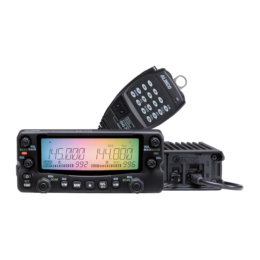
VHF/UHF FM Transceiver DR-735T(2) DR-735T(2) DR-735T Instruction Manual Thank you for purchasing your new Alinco transceiver. This Instruction manual contains important safety and operating instructions. Please read this manual carefully before using the product and keep it for future reference. -
Page 2: Notice / Compliance Information Statement
Copyright © 2016 All right reserved. No part of this document may be reproduced, copied, translated or transcribed in any form or by any means without the prior written permission of Alinco. Inc., Osaka, Japan. English Edition Printed in Japan. - Page 3 To prevent any hazard during operation of Alinco’s radio product, in this manual and on the product you may fi nd symbols shown below. Please read and understand the meanings of these symbols before starting to use the product. This symbol is intended to alert the user to an immediate...
- Page 4 WARNING Be sure to reduce the audio output level to minimum before using an earphone or a headset. Excessive audio may damage hearing. Do not open the unit without permission or instruction from the manufacturer. Unauthorized modification or repair may result in electric shock, fire and/or malfunction.
- Page 5 WARNING Do not open the unit and its accessories. Please consult with your local dealer of this product for service and assistance. Do not use the product in proximity to a TV or a radio. It may cause interference or receive interference.
-
Page 6: Notice To California Resident Users
first sight of forthcoming thunderstorm and lightning. Thank you very much for purchasing this excellent Alinco transceiver. Our products are ranked among the finest in the world. This radio has been manufactured with state of the art technology and it has been tested carefully at our factory. - Page 7 Thank you very much for purchasing this excellent Alinco transceiver. Our products are ranked among the finest in the world. This radio has been manufactured with state of the art technology and it has been tested carefully at our factory. It is designed to operate to your satisfaction for many years under normal use.
- Page 8 The standard accessories may vary slightly depending on the version you have purchased. Please contact your local authorized Alinco dealer should you have any questions. Standard accessories may change without notice. Warranty Policy Please refer to any enclosed warranty information or contact your authorized Alinco dealer/distributor for the warranty policy before purchase.
- Page 9 Use a regulated power supply capable of providing continuous current of 12A or more. Power supplies that do not meet does specifications may cause malfunction and/or damage to the radio and will void the warranty. Alinco offers excellent communication-grade power supplies as optional accessories. Please contact your local authorized Alinco dealer.
- Page 10 Initial Installation DC voltage range for operating this transceiver is DC 11.7V to 15.8V. Transceiver will not operate out of this range. Inspect cable and connection IMPORTANT regularly to be sure there is not any damage or burning. power supply lead Black DC power cable...
- Page 11 Initial Installation ④ Match the catch in the main unit with the slot in the front panel and fit the front panel into the main unit. ⑤ Slide the front panel unit until it locks securely in place. By using the optional separation kit EDS-30, you can use the control and the main unit in separate positions.
- Page 12 Initial Installation Use a 50 coaxial cable to connect the antenna. Mobile antennas require an appropriate mounting base for proper installation and operation. For more Screw-fixed base information, see the documentation for your antenna. Magnet base After installing your antenna, ensure that you have the best possible SWR reading.
- Page 13 There are 3 types of key operations; simply press, press after pressing [FUNC] key while FUNC appears on the display, or press and hold. • [Press] refers to one time quick press and remove finger. • [FUNC + this Key] refers to one time press [FUNC] key and then pressing this key while FUNC appears on the display.
- Page 14 Controls, Connectors, and Display Functions that requires press and holding to be activated Function Left band [VOL] knob Switches between VHF/Air-Band and UHF on the left band (P.19) Right band [VOL] Knob Switches between UHF/VHF and Air-Band on the right band (P.19) Left band dial Switches between VFO and memory scan on the left band.
- Page 15 Controls, Connectors, and Display ④ ① ② ⑤ ③ ⑥ Function Connects an external 8 speaker. Output audio from right band. When External Speaker Jack 1 [SP1] another speaker is not connected to [SP2], left band audio hear through internal speaker. Also [SP1] used for connecting clone or PC cables. Connects an external 8 speaker.
- Page 16 Controls, Connectors, and Display Function Appears when advanced set mode is available. (P.48) Appears during AM reception. (P.36) Appears during transmission when other band is set for mute. (P.52) Appears when APO function is activated. (P.49) Appears when setting the key lock. (P.62) Appears when [FUNC] key is pressed.
- Page 17 Controls, Connectors, and Display ② ① ③ ⑥ ④ ⑤ Function Increase the frequency, memory channel number, or setting value. DOWN Decrease the frequency, memory channel number, or setting value. Press the PTT (Push-To-Talk) key to transmit. Also press this key to confirm MAIN PTT your selection.
- Page 18 By press and holding the PWR key the power is turned on. By press and PWR key holding the PWR key again, the power is turned off. To avoid accidentally turn on/off, PWR key operation is designed for press and hold. In this instruction manual the MAIN band refers to the band which VOL knob selected for transmitting with MAIN icon on the display.
- Page 19 Basic Operations high high Adjust threshold level of the squelch. A squelch eliminates the background noise when a signal is not received. Turn the SQL knob clockwise until white-noise (the background SQL knob for VOL knob for noise when a signal is not received) and [BUSY] icon on the left band Right band display disappears.
- Page 20 Basic Operations Be sure to have the unit connected to the appropriate antenna, powered on, set the audio volume and squelch level properly on both the MAIN and SUB bands. Select the desired band and browse frequencies or select desired frequency to listen to ongoing communications.
- Page 21 Basic Operations This function is for monitoring the transmission frequency instead of reception frequency in repeater operation. This technique is commonly used to check if it is possible to communicate without using repeater by Auto repeater setting monitoring the accessing station’s signal strength. Set SHIFT first.
- Page 22 Basic Operations Releasing the PTT key will complete the transmission and the unit will return to the receive mode. Pressing the DOWN key together with the PTT key will transmit the CALL tone signal. DR-735T will transmit the Tone Burst signal. tone signal.
- Page 23 Please read the following pages thoroughly prior to changing any parameters. The parameters in set mode cannot be set without entering the set mode. IMPORTANT By entering the set mode, some of the radio’s operating parameters can be changed to suit your application.
- Page 24 Set mode Press and hold FUNC key to enter the Set mode. Menu number and parameter will appear on the display. Default display Select a menu by pressing left dial knob to decrease menu number or right dial knob to increase menu number, or UP/ DOWN keys on the microphone.
- Page 25 Set mode This is to select the channel step to be used in the VFO mode. Refer to the P.21for the sequence of the actual steps and how they are displayed. Operating modes are determined by the modulation of the radio signals. The transceiver has total 5 operating modes (AUTO, FM, NFM, AM, NAM modes).
- Page 26 Set mode Pressing any key other than the dial knob or the UP/DOWN keys will complete the setting and the unit will exit the parameter setting mode. IMPORTANT Pressing PTT switch will not exit the set mode setting. This is to select the scan resume condition. The BUSY setting resumes scanning when received signal is gone and TIME setting allows the radio to resume scanning after 5, 10, 20,30 or 60 seconds.
- Page 27 Set mode Rotate the dial to select a desired item. SKIP : Skips unwanted channels that inconveniently stop scanning. ALL : Repeatedly scans all frequenciesover the entire band regardless of the SKIP or FAV channels. FAV : Scans only favorite channels. Pressing any key other than the dial knob or the UP/DOWN keys will complete the setting and the unit will exit the parameter...
- Page 28 Set mode Press and hold FUNC key to enter the parameter set mode. Press dial to select menu 07. Factory default setting is [OFF]. Rotate the right dial to select a desired item. This setting is individual regardless of the band or VFO. Pressing any key other than the dial knob or the UP/DOWN keys will complete the setting and the unit will exit the parameter...
- Page 29 Set mode This is the mode to select color mode for various conditions. Press and hold FUNC key to enter the parameter set mode. Press dial to select menu 09. By rotating the right dial, the display MEMORY GRADTN RAINBW changes as shown and the color mode function selection is changed.
- Page 30 Set mode Press and hold FUNC key to enter the parameter set mode. Press dial to select menu 10. By rotating the dial, the display changes SB CL0 SB CL9 as shown and the illumination color selection during the waiting time is changed.
- Page 31 Set mode Press and hold FUNC key to enter the parameter set mode. Press dial to select menu 12. By rotating the dial, the display changes TX CL0 TX CL9 as shown and the illumination color selection during transmitting is changed. Pressing any key other than the dial knob or the UP/DOWN keys will complete the setting and the unit will exit the parameter...
- Page 32 Set mode This is back light timer setting when radio is operated refers to dimmer setting on menu 13. Press and hold FUNC key to enter the parameter set mode. Press dial to select menu 14. By rotating the right dial, the display changes as shown and the back light timer is changed.
- Page 33 Set mode The attenuator prevents distortion of a desired signal by very strong RF signals near the desired frequency or when very strong electric fields, such as from a broadcasting station, are present at your location. Press and hold FUNC key to enter the parameter set mode.
- Page 34 Set mode Memory reset (P.73) will delete memory channels data even when memory protection is set ON. NOTE Channel’s data can be changed temporally even when memory protection is set ON; however change will not restore. This is to allocate desired function to the sub PTT switch on EMS-79 microphone. Press and hold FUNC key to enter the parameter set mode.
- Page 35 Set mode This is to change the time for push and holding key for switching band, scan, set mode, key lock, CALL, recalling channel, programming memory in easy mode, etc. Press and hold FUNC key to enter the parameter set mode. Press dial to select menu 19.
- Page 36 Set mode This is to restore set mode settings. This function is useful to restore settings after resetting the radio. After Adjusting parameters in set mode use this function to restore the settings. IMPORTANT Color setting and some other setting out of set mode cannot be restored. Press and hold FUNC key to enter the parameter set mode.
- Page 37 This is to use the unit as a single-band transceiver only for VHF or UHF, by eliminating the display on the one side. Press FUNC key and while [FUNC] appears on the display press VOL knob for desired side. Eliminated band will not operate.
- Page 38 Useful functions To disable this function, delete the APL memory channel data. Shift, offset, CTCSS and DCS functions cannot be changed during VFO IMPORTANT auto program operation. Use this function to automatically search for signals. In the set mode, chose TIMER mode or the BUSY mode to determine the desired resuming condition.
- Page 39 Useful functions Enter Memory mode for desired band. Sequence is same as in VFO scan. Use UP/ DOWN keys for Commands. Enter the dual memory mode. Sequence is same as in VFO scan. Use UP/DOWN keys for Commands. A memory channel set as skip-channel will be excluded from scanning during memory scan. This designation can be set even after the memory is programed.
- Page 40 Useful functions This is a type of VFO scan, which is done by setting the frequency range of the VFO into the P A and P B channels, it only scans between those frequencies. Each band can be set for 5 pairs.
- Page 41 Useful functions This function automatically searches for the CTCSS tone an incoming signal might carry. This feature is useful to search for the encoding tone of a repeater, or to communicate with a station operating in TSQ (CTCSS squelch) mode. Press FUNC key then repeat pressing key while FUNC appears on the display to enter the CTCSS decode setting mode.
- Page 42 Useful functions This function automatically searches for the DCS tone an incoming signal might carry. This feature is useful to search for the encoding tone of a repeater, or to communicate with a station operating in DCS (Digital Code Squelch) mode. Press FUNC key then repeat pressing key while [FUNC] appears on the display to enter the DCS decode setting mode.
-
Page 43: Press And Hold
Useful functions Various functions can be assigned to key. There is not a factory default allocation for this key, therefore only beep will be heard by pressing this key. Enter to set mode and select desired item. Press and hold key until beep sound to be heard. - Page 44 Useful functions Many repeaters require a CTCSS tone or a DCS encode setting as a “key” to access a repeater system, or a receiver using CTCSS or DCS squelch, so called “selective-calling”. Sometimes, CTCSS or DCS decode features are used on the output of a repeater so they can be used to open a squelch. In this mode, regardless of the main squelch status, the audio can be heard ONLY when the matching tone/code signal is received.
- Page 45 Useful functions CTCSS chart (Hz): 67.0 69.3 71.9 74.4 77.0 79.7 82.5 85.4 88.5 91.5 94.8 97.4 100.0 103.5 107.2 110.9 114.8 118.8 123.0 127.3 131.8 136.5 141.3 146.2 151.4 156.7 162.2 167.9 173.8 179.9 186.2 192.8 203.5 210.7 218.1 225.7 233.6 241.8...
- Page 46 Useful functions This function is used to transmit a memorized DTMF code, such as a telephone number, up to 16 (0 to 9/ABCD#*-) digits. Press and hold FUNC key then press MW key. Rotate left dial or press UP/DOWN keys on the microphone to select channel number.
- Page 47 Useful functions Press the FUNC key or the PTT key to enter the digital communication mode. Repeat step 2 to exit and return to the analogue FM mode. To cancel the digital communication mode, repeat step2. EJ-47U When activating this setting, a code is displayed and switched by rotating the dial.
-
Page 48: Setting On The Master Side
Useful functions This feature will copy the programmed data and parameters in the master unit to slave units. Connection Make a cable using 3.5 mm stereo-mini plugs as Plug configuration (both for Master/Slave) shown. Make a master unit by setting and programming it as desired. -
Page 49: Entering A Frequency Directly
Useful functions Entering a frequency directly Frequencies can be entered directly by pressing the numerical keys of the microphone. Set the microphone DTMF/REMOTE switch to the REMOTE position. DTMF keys can be used to enter total 6 digits from the digit for 100 MHz to digit for1 KHz. - Page 50 Resetting the unit returns all programmed contents to their factory default settings. By using restore function (menu. 21),(P.47)setting can be restored but memory channel data cannot be restored. Use cloning software, interface cable and computer to save and restore memory data. This is to reset setting for VFO, memory and advanced memory modes.
-
Page 51: Demonstration Mode
Maintenance / Reference Please check the list below before concluding that the transceiver is faulty. If a problem persists, reset the transceiver. This can sometimes correct erroneous operation. Problem Possible Causes Potential Solutions Power is on, nothing a. + and – polarities of power a. - Page 52 General DR-735T DR-735T(2) Frequency coverage: 144.000 ~ 145.995MHz 108.000 ~ 173.995MHz 144.000 ~ 145.995MHz Transmit 430.000 ~ 439.995MHz Frequency coverage: 136.000 ~ 173.995MHz 108.000 ~ 173.995MHz Receive 400.000 ~ 479.995MHz Operating mode Antenna impedance Operating temperature -10°C ~ +60°C Power requirement DC13.8V±15% (11.7 ~ 15.8V) Frequency stability ±2.5ppm...
- Page 53 ALINCO,INC. Head Office: Yodoyabashi-Dai Building 13th Floor 4-9, 4-Chome, Koraibashi, Chuo-ku, Osaka 541-0043, Japan Phone: +81-6-7636-2362 Fax: +81-6-6208-3802 http://www.alinco.com/ E-mail: export@alinco.co.jp Printed in Japan Copyright Alinco, Inc. PS0667A FNEG-NM...
Need help?
Do you have a question about the DR-735T(2) and is the answer not in the manual?
Questions and answers