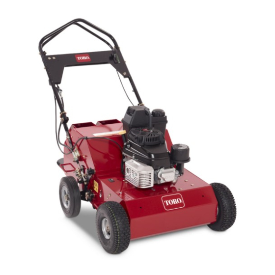
Toro 23515 Service Manual
21 inch
Hide thumbs
Also See for 23515:
- Operator's manual (44 pages) ,
- Operation manual (24 pages) ,
- Operator's manual (32 pages)
Table of Contents
Advertisement
Quick Links
Advertisement
Table of Contents

Related Manuals for Toro 23515


Summary of Contents for Toro 23515
- Page 1 Residential and LCE Products 21 inch Aerator Service Manual...
- Page 3 For information specific to the engines used on this unit, refer to the appropriate engine manufacturer’s service and repair instructions. The Toro 21” Aerator, model year 2012-2014, is covered in this manual. The manual may also be specified for use on later model products.
- Page 4 ABOUT THIS MANUAL THIS PAGE INTENTIONALLY LEFT BLANK.
-
Page 5: Table Of Contents
Replacing Pivot Shaft - Serial 312000001 & up, Serial 313000001 & up ..........3-13 Replacing Pivot Shaft - Serial 314000001 & up ..................3-16 Replacing the Front Drive Axle - All Models ....................3-20 TOC-1 Toro 21” Aerator Service Manual... - Page 6 Transmission Installation .........................4-10 Engine Subsystem............................4-13 Engine Replacement .............................4-14 Engine Removal ............................4-14 Engine Installation ...........................4-14 5 - Tine System Tines Subsystem .............................5-1 Checking/Replacing Tines ..........................5-2 Tine Assembly Replacement ...........................5-3 Tine Assembly Removal ..........................5-3 Tine Assembly Installation .........................5-6 TOC-2 Toro 21” Aerator Service Manual...
-
Page 7: Safety Information
This manual is intended as a service and repair manual Bloomington, MN 55420 only. The safety instructions provided herein are for troubleshooting, service, and repair of the Toro 30” Aerator. The 21” Aerator/Seeder operator’s manual Think Safety First Avoid unexpected starting of engine... - Page 8 SAFETY INFORMATION THIS PAGE INTENTIONALLY LEFT BLANK. Toro 21” Aerator Service Manual...
-
Page 9: Specifications & Maintenance
Starter Recoil Only Fuel Tank Volume 1.0 US gal (3.8 L) Power System: Transmission Hydro-Gear T2 Toro premium hydro oil or Hydraulic Fluid Mobil1 15w-50 Hydraulic Fluid Capacity 65.9 oz. (1950ml) Ground Speed (fwd/rev) 4 mph/2.2 mph Drive Tires (pneumatic) 11 x 4.00 - 4... -
Page 10: Specifications 2014 Models (Serial 314000001 & Up)
Starter Recoil Only Fuel Tank Volume 1.0 US gal (3.8 L) Power System: Transmission Hydro-Gear T2 Toro premium hydro oil or Hydraulic Fluid Mobil1 15w-50 Hydraulic Fluid Capacity 65.9 oz. (1950ml) Ground Speed (fwd/rev) 4 mph/2.2 mph Drive Tires (pneumatic) 11 x 4.00 - 4... -
Page 11: Handle Adjustment (Serial 314000001 & Up)
B. Lift link straps middle holes Fig. 001 fig. 7 G023023 Front handle position - lowest height A. Trunion bracket - C. Mounting bolt location bottom hole D. Handle hardware - B. Lift link straps front holes Toro 21” Aerator Service Manual... -
Page 12: Adjusting The Coring Depth (All Models)
B. Lift link straps rear holes 2. Secure the handle with both mounting bolts. 3. Adjust the tine-control lever. Fig. 004 fig. 17 G023022 A. Wheel stop C. Indicator hole B. Nuts D. Indicator notches Toro 21” Aerator Service Manual... -
Page 13: Adjusting The Tine Control Lever 2014 Models (Serial 314000001 & Up)
(Fig. 004). Fig. 005 fig. 18 G023095 A. Pivot shaft assembly C. Wheel arm assembly B. 4.8 inches (12cm) Toro 21” Aerator Service Manual... - Page 14 9. Turn the link rod, by hand, until the ball joint on the tine-control lever is tight against the handle. 10. Tighten both jam nuts on the link rod next to the ball joints. Toro 21” Aerator Service Manual...
-
Page 15: Lift Drop Cable Adjustment 2012-13 Models (Serial 312000001 & Up, Serial 313000001 & Up)
2. Adjust the Cable Housing Anchor Nuts so there are an equal number of threads on each end and re- tighten (B - Fig. 010). Fig. 011 DSCN-0024 Fig. 008 DSCN-0016a Fig. 012 DSCN-0032 Fig. 013 DSCN-0029 Fig. 009 011a Fig. 010 DSCN-0019a Toro 21” Aerator Service Manual... -
Page 16: Recommended Maintenance Schedule
Before performing any maintenance, park the unit on a level surface, stop the engine, and disconnect the spark plug wire. Set the wire aside so that it does not accidentally contact the spark plug. Toro 21” Aerator Service Manual... -
Page 17: Accessing The Tines & Tipping The Machine
If you operate the machine with the rear access panel removed some one could be severely injured by contact with the moving tines or by flying debris. Always securely install the rear access panel before operating the machine. Toro 21” Aerator Service Manual... -
Page 18: Greasing The Tine Shaft Bearings
Important: Do not raise the rear of the machine. Raising the rear of the machine will cause the engine to flood and the air cleaner to be fouled with gasoline. Fig. 016 fig. 23 G022403 Fig. 017 tine grease fittings_a 2-10 Toro 21” Aerator Service Manual... -
Page 19: Servicing The Air Cleaner
8. Wipe up any oil that spilled and lower the machine to the ground when finished. Note: Use a new paper air filter if you discarded the old one. 8. Install the air filter assembly and cover. Toro 21” Aerator Service Manual 2-11... -
Page 20: Changing The Engine Oil
3. Disconnect the wire from the spark plug. 4. Place a drain pan on the ground to the right of the machine. Fig. 021 fig. 26 G017582 A. Oil drain plug B. Oil filter 2-12 Toro 21” Aerator Service Manual... -
Page 21: Changing The Oil Filter
Note: If you overfill the engine, pour some oil out of 9. Install the dipstick securely. 10. Recycle the used oil according to local codes. Fig. 022 fig. 26 G017582 A. Oil drain plug B. Oil filter Toro 21” Aerator Service Manual 2-13... -
Page 22: Servicing The Spark Plug
11. Check and add oil to compensate for the oil in the oil a spark plug may damage the threads in the filter. Do not overfill. cylinder head. 12. Recycle the used oil filter according to local codes. 8. Connect the wire to the spark plug. 2-14 Toro 21” Aerator Service Manual... -
Page 23: Check The Spark Arrester (If Equipped)
(soak in solvent if necessary). Replace the spark arrester when finished. Fig. 025 fig. 29 G017588 A. Fuel filter B. Fuel valve Toro 21” Aerator Service Manual 2-15... -
Page 24: Replacing The Fuel Filter
6. Remove the filter from the fuel lines. 7. Install a new filter and move the hose clamps close to the filter (Fig. 026). 8. Remove the clamps from the fuel lines. 9. Open the fuel shutoff valve. 2-16 Toro 21” Aerator Service Manual... -
Page 25: Checking The Tire Pressure
20 pounds (9kg) of force (Fig. 028). If A. Valve stem a chain flexes more than 1/8” (3mm), tighten it as follows: Fig. 028 fig. 31 G023864 A. Flex in the chain Toro 21” Aerator Service Manual 2-17... -
Page 26: Checking The Hydrostatic Drive Belt
C. Tighten the idler sprocket nut and torque it to 30 ft-lbs. (40.6 Nm). 4. Repeat step 3 to test the chain tension and tighten it as needed. 5. Repeat this procedure for the other tine drive chain. 2-18 Toro 21” Aerator Service Manual... -
Page 27: Adjusting The Machine Ground Speed 2012-13 Models (Serial 312000001 & Up, Serial 313000001 & Up)
B. Push the idler pulley to the left to tighten the belt. Fig. 031 fig. 29 G020483 C. Tighten the idler pulley nut and torque it to 30 ft- A. Bolts B. Cable attachment lbs. (40.6 Nm). bracket Toro 21” Aerator Service Manual 2-19... - Page 28 • Move the lower nut to the end of the thread (Fig. 033). Note: Ensure that the bail will reach the handle after the transmission is engaged. Fig. 032 fig. 30 G020484 A. Nut B. Jam nut Fig. 033 fig. 31 G020485 A. Lower nut 2-20 Toro 21” Aerator Service Manual...
-
Page 29: Adjusting The Self-Propel Drive 2014 Models (Serial 314000001 & Up)
(up to 1/8” (3mm)) between the self- propel bail and the handle (Fig. 035). Fig. 034 fig. 32 G020486 Fig. 035 fig. 34 G023021 A. Nuts A. Self-propel drive bail C. Top/Bottom adjustment B. Cable nuts Toro 21” Aerator Service Manual 2-21... -
Page 30: Changing The Hydraulic Transmission Fluid
6. Secure the new tine with the bolt and nut you removed previously and torque them to 30 ft-lbs. (40.6 Nm). 7. When all tines have been inspected and replaced as needed, lower the machine to the ground and engage the hydrostatic drive. 2-22 Toro 21” Aerator Service Manual... -
Page 31: Troubleshooting
3. The chains are not properly Dealer. tensioned. 3. Adjust the tine drive chain. The tines drop out of transport when 1. Tine-control lever is out of 1. Adjust the tine-control lever. the handle is folded over. adjustment. Toro 21” Aerator Service Manual 2-23... - Page 32 SPECIFICATIONS & MAINTENANCE THIS PAGE INTENTIONALLY LEFT BLANK. 2-24 Toro 21” Aerator Service Manual...
-
Page 33: Chassis
Fig. 037 subsystem handles 2012 A. Mount - Handle E. Control - Throttle B. Handle - Assembly F. Cable - Lift, Lower C. Tube - Control G. Cable - Drive D. Tube - Lift, Handle Toro 21” Aerator Service Manual... -
Page 34: Handle Subsystem - 2014 (Serial 314000001 & Up)
Adjust cable so when drive handle (B) is at full speed, there is .03-.10” gap between drive handle #2 and handle #1 3-4 threads exposed on the front side of the front nut. Assemble linkage into bottom hole. Assemble handle into middle position on frame. Toro 21” Aerator Service Manual... -
Page 35: Engine Frame Subsystem - 2012 (Serial 312000001 & Up), 2013 (Serial 313000001 & Up)
G. Cover - transaxle J. Pulley B. Stop-depth E. Sprocket - idler H. Bracket - mount axle, K. Bracket - mounting, C. Cover - assembly F. Guard cable Brocket - mount axle, L. weight - aerator Toro 21” Aerator Service Manual... -
Page 36: Engine Frame Subsystem - 2014 (Serial 314000001 & Up)
A. Frame - service D. Bracket - mount axle, F. Pulley H. Cover, transaxle B. Stop - depth G. Weight - areator Bracket - mounting C. Sprocket - idler E. Bracket - mount axle, cable Toro 21” Aerator Service Manual... -
Page 37: Height Linkage
(Fig. 041) Fig. 041 subsys ht linkage 2012a A. Shaft - pivot C. Link - connecting E. Arm - lift G. Screw - set B. Arm - wheel D. Wheel - transport F. Key - woodruff Toro 21” Aerator Service Manual... -
Page 38: Subsystem - Height Linkage - 2014 (Serial 314000001 & Up)
Wheel pivot arms must rotate freely on frame wheel arem and turns freely (2x). pivot pins (2x). Apply anti-sieze to this area prior to assembly Pivot shaft assembly must rotate freely in frame (2x). bushings. Toro 21” Aerator Service Manual... -
Page 39: Drive Cable Removal & Installation
2. From under the machine, loosen the cable lock nuts and remove the linkage that connects the cable to the transmission. Remove the cable (Fig. 044). Fig. 045 fig. 30 G020484 A. Nut B. Jam nut Fig. 044 drive cable 2 Toro 21” Aerator Service Manual... - Page 40 Note: The reverse speed should be around 2.0 MPH Note: Ensure that the bail will reach the handle after (3.2km/h). the transmission is engaged. Fig. 046 fig. 31 G020485 A. Lower nut Fig. 047 fig. 32 G020486 A. Nuts Toro 21” Aerator Service Manual...
-
Page 41: Tine Control Cable Removal & Installation - Serial 312000001 & Up, Serial 313000001 & Up
Loosen the lock nuts that connects the secure the cable to the bracket (Fig. 051). cable to the stationary bracket. Remove cable (Fig. 049). Fig. 051 jam nut 2 Fig. 049 lift lower cable 2 Toro 21” Aerator Service Manual... - Page 42 1a 7. Adjust the cable housing jam nuts so there are an equal number of threads on each side. Tighten the jam nuts (Fig. 053). Fig. 053 upper jam nuts 2a 3-10 Toro 21” Aerator Service Manual...
-
Page 43: Adjusting Handle - Serial 314000001 & Up
Rear handle position - Highest height A. Trunion bracket - C. Mounting bolt location top hole D. Handle hardware - B. Lift link straps rear holes 2. Secure the handle with both mounting bolts. 3. Adjust the tine-control lever. Toro 21” Aerator Service Manual 3-11... -
Page 44: Adjusting The Tine Control Lever - Serial 314000001 & Up
18 G023095 A. Handle pivot bolt D. Lift link strap ball joint A. Pivot shaft assembly C. Wheel arm assembly B. Lower ball joint bolt E. Adjust here B. 4.8” (12cm) C. 1/4” (6mm) 3-12 Toro 21” Aerator Service Manual... -
Page 45: Replacing Pivot Shaft - Serial 312000001 & Up, Serial 313000001 & Up
9. Turn the link rod, by hand, until the ball joint on the tine-control lever is tight against the handle (Fig. 059). 10. Tighten both jam nuts on the link rod next to the ball Fig. 061 snap ring & washers_a joints. Toro 21” Aerator Service Manual 3-13... - Page 46 7. On the opposite side, remove the snap rings and washers from the wheel arm and lift arm (Fig. 065). Note: There are two set screws (Fig. 063). Fig. 065 wheel & lift arm_a Fig. 063 set screws 1 3-14 Toro 21” Aerator Service Manual...
- Page 47 (Fig. 069). assembly from the shaft. Replace the shaft with new, inserting it into the wheel and lift arm assembly (Fig. 067). Fig. 069 pivot shaft hole_a Fig. 067 new shaft_a Toro 21” Aerator Service Manual 3-15...
-
Page 48: Replacing Pivot Shaft - Serial 314000001 & Up
2. Remove the two bolts from the right hand lift arm (Fig. 071). Fig. 070 install snap rings_a Fig. 071 RH lift arm 3. Remove the snap ring from the pivot shaft (Fig. 072). Fig. 072 PS snap ring 3-16 Toro 21” Aerator Service Manual... - Page 49 5. Remove the jam nut that is connected from the ball joint to the lift link (Fig. 074). 7. Remove the pivot shaft from the left side of the machine (Fig. 076). Fig. 074 ball joint nut Fig. 076 pivot shaft asm Toro 21” Aerator Service Manual 3-17...
- Page 50 Fig. 079 RH side hole_a 9. Insert new shaft through LH side of machine (Fig. 11. Install the RH lift arm (Fig. 080). 078). Fig. 080 RH lift arm replace Fig. 078 pivot shaft asm 3-18 Toro 21” Aerator Service Manual...
- Page 51 13. Install the two bolts on the right hand lift arm (Fig. 082). 15. Install the jam nut that is connected from the ball joint to the lift link (Fig. 084). Fig. 082 RH lift arm Fig. 084 ball joint nut Toro 21” Aerator Service Manual 3-19...
-
Page 52: Replacing The Front Drive Axle - All Models
Remove lock collar (Fig. 088). Fig. 085 wheels_a 3. Remove the keys and bushings from both sides of the axle (Fig. 086). Fig. 088 lock collar 2_a Fig. 086 3-20 Toro 21” Aerator Service Manual... - Page 53 (Fig. 091). 7. Rotate the shaft until the master link is accessible on the front drive shaft chain. Remove the master link and chain (Fig. 090). Fig. 091 alignment_a Fig. 090 master link 1_a Toro 21” Aerator Service Manual 3-21...
- Page 54 Apply Loctite 242 to the set ® screws and tighten to 12-14 in-lbs. (1.4-1.6 Nm) (Fig. 092). Fig. 092 lock collar 3_a 15. Install the bushings and keys. 16. Install the wheels and snap rings. 3-22 Toro 21” Aerator Service Manual...
-
Page 55: Aerator Transaxle Subsystem
Set locking collar in the same direction as shaft rotation - assume forward tire rotation (clockwise on RH side). Set locking collar in the same direction as shaft rotation - assume forward tire rotation (counter-clockwise 4 places). Toro 21” Aerator Service Manual... -
Page 56: Transmission Replacement
Note: Using two people or an overhead hoist to lift the machine will make this easier. 6. Loosen the nut on the idler pulley to make the belt go slack (Fig. 096). Fig. 096 Fig. 094 1-1a Toro 21” Aerator Service Manual... - Page 57 8. Remove and retain the connecting link from the front axle chain sprocket. Remove chain (Fig. 098). 10. Remove and retain the connecting link from the drive chains. Remove the drive chains from the transmission sprockets (Fig. 100). Fig. 098 Fig. 100 Toro 21” Aerator Service Manual...
- Page 58 13. Remove the transmission from the chassis (Fig. top of the deck (Fig. 101). 103). Fig. 101 Fig. 103 12. Remove the four bolts holding the transmission to the support brackets (Fig. 102). Fig. 102 Toro 21” Aerator Service Manual...
-
Page 59: Changing Transmission Oil
#10-32 x 1/2” self-tapping self-tapping screw and torque it to 25 in-lbs (2.8 Nm) screw and ratchet fastener holding the expansion (C) (Fig. 107). tank to the housing (Fig. 105). Fig. 107 Fig. 105 Toro 21” Aerator Service Manual... -
Page 60: Servicing The Jack Shaft & Output Shaft
Shaft of the fill port (A) (Fig. 108). Jack Shaft & Output Shaft Removal Note: Toro Premium Hydro Oil is recommended. Mobil 1 15w-50 is an acceptable alternative. 1. Remove the transmission as outlined in “Transmission Removal” in this chapter. - Page 61 (Fig. 114). 5. Insert a pin punch into the recessed hole in the lock collar. Tap the punch to turn the collar to loosen the collar (Fig. 112). Fig. 114 Fig. 112 Toro 21” Aerator Service Manual...
- Page 62 To remove sprocket from shaft, tap the collar to loosen it from the bearing (Fig. 116). insert the assembly into a press and press the sprocket off (Fig. 118). Fig. 116 Fig. 118 Toro 21” Aerator Service Manual...
-
Page 63: Jack Shaft & Output Shaft Installation
(Fig. 119). Fig. 121 Fig. 119 4. The sprockets should be exactly aligned with one another (Fig. 122). 2. Install the bearing plate, bearings, and bearing retainers (Fig. 120). Fig. 122 Fig. 120 Toro 21” Aerator Service Manual... -
Page 64: Transmission Installation
7. Insert a pin punch into the recessed hole in the outer jack shaft lock collar and the output shaft collar. Tap the punch to turn the collar to tighten. Apply Loctite 242 to the set screw and torque to 12-14 ft-lbs. (16- 19 Nm). 4-10 Toro 21” Aerator Service Manual... - Page 65 The belt should flex no more than 1/8 inch (3mm). If it flexes more than that, re-tension the belt (Fig. 130). Fig. 128 Fig. 130 fig. 33 G013125 A. Pump drive belt C. Idler pulley nut B. Idler pulley Toro 21” Aerator Service Manual 4-11...
- Page 66 (Fig. 132). Fig. 132 fig. 31 G023864 A. Flex in the chain Fig. 134 fig. 34 G023021 A. Self-propel drive bail C. Top/bottom adjustment B. Cable nuts 4-12 Toro 21” Aerator Service Manual...
-
Page 67: Engine Subsystem
Loosen throttle bracket assembly mounting bolts, adjust bracket forward/aft to achieve desired full throttle position. Retighten bolts. Apply anti-seize to engine crankshaft and engine pulley prior to assembly. Pulley must be assembled tight to step on crankshaft. Toro 21” Aerator Service Manual 4-13... -
Page 68: Engine Replacement
4. Remove the four engine mounting bolts (Fig. 137). Fig. 138 4. Add fuel and oil to engine and test run. a. Set engine RPM to 3700 ± 50 RPM. Fig. 137 5. Remove engine. 4-14 Toro 21” Aerator Service Manual... -
Page 69: Tine System
Tighten set screws in bearings, torque to 12-14 ft-lbs. Tine idler must turn freely. Orient the tines so that the leading edge of tine is towards the front of the machine. Toro 21” Aerator Service Manual... -
Page 70: Checking/Replacing Tines
A. Tine assembly C. Bolt and nut B. Tine 6. Secure the new tine with the bolt and nut and torque to 30 ft-lbs. (40.6 Nm). 7. Replace the access cover and reconnect the spark plug wire. Toro 21” Aerator Service Manual... -
Page 71: Tine Assembly Replacement
Note: Using two people or an overhead hoist to lift the machine will make this easier. 6. Remove and retain the connecting link from the drive chains. Remove the drive chains from the transmission and tine sprockets (Fig. 144). Fig. 142 Fig. 144 Toro 21” Aerator Service Manual... - Page 72 10. Slide the snap rings on the tine shaft all the way to the outer stationary spyder (Fig. 148). 8. Loosen and remove the two nuts and bolts, then remove the lock collar bearings from both sides of the unit (Fig. 146). Fig. 148 Fig. 146 Toro 21” Aerator Service Manual...
- Page 73 11. Loosen the flange bearing bolts and remove the nuts 13. Remove the tine assembly and chain guard (Fig. (Fig. 149). 151). Fig. 149 Fig. 151 12. Slide the inner spyder toward the outer stationary spyder (Fig. 150). Fig. 150 Toro 21” Aerator Service Manual...
-
Page 74: Tine Assembly Installation
Torque to 17 ft-lbs. (23 Nm) (Fig. 155). 2. Place the chain guard on the opposite side tine assembly and install into chassis. Install all the flange bearing bolts and nuts and hand tighten the nuts (Fig. 153). Fig. 155 Fig. 153 Toro 21” Aerator Service Manual... - Page 75 8. Install and tighten the drive chains as outlined in “Transmission Installation” on page 4-10. 9. Carefully remove the hoist hooks and lower the machine to the ground. Raise and lock the handle into the operating position. Fig. 157 Toro 21” Aerator Service Manual...
- Page 76 TINE SYSTEM THIS PAGE INTENTIONALLY LEFT BLANK. Toro 21” Aerator Service Manual...
- Page 78 21 inch Aerator Service Manual Form Number 492-9335...