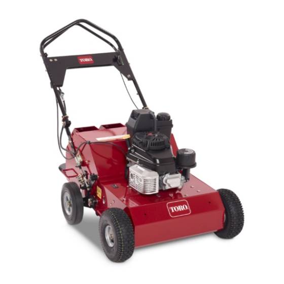
Toro 23515 Operator's Manual
21in walk-behind aerator
Hide thumbs
Also See for 23515:
- Service manual (78 pages) ,
- Operator's manual (44 pages) ,
- Operation manual (24 pages)

Related Manuals for Toro 23515


Summary of Contents for Toro 23515
- Page 1 Form No. 3397-179 Rev A 21in Walk-Behind Aerator Model No. 23515—Serial No. 315000001 and Up Model No. 33515—Serial No. 315000001 and Up *3397-179* A Register at www.Toro.com. Original Instructions (EN)
- Page 2 This manual uses 2 words to highlight information. Important calls attention to special mechanical information You may contact Toro directly at www.Toro.com for product and Note emphasizes general information worthy of special safety and operation training materials, accessory information, attention.
-
Page 3: Table Of Contents
Contents Safety Improper use or maintenance by the operator or Safety ................3 owner can result in injury. To reduce the potential Safe Operating Practices........... 3 for injury, comply with these safety instructions and Slope Indicator ............5 always pay attention to the safety alert symbol, which Safety and Instructional Decals ......... -
Page 4: Slope Operation
Replace all worn or damaged decals. Do not change the engine governor setting or overspeed the engine. • Use only Toro-approved attachments. The warranty • Raise the tines, stop the machine, and stop the engine may be voided if the machine is used with unapproved before leaving the operator’s position for any reason. -
Page 5: Slope Indicator
Slope Indicator G011841 Figure 3 This page may be copied for personal use. 1. The maximum slope you can safely operate the machine on is 20 degrees. Use the slope chart to determine the degree of slope of hills before operating. Do not operate this machine on a slope greater than 20 degrees. Fold along the appropriate line to match the recommended slope. -
Page 6: Safety And Instructional Decals
Safety and Instructional Decals Safety decals and instructions are easily visible to the operator and are located near any area of potential danger. Replace any decal that is damaged or lost. 117–2718 119-0217 121-6150 1. Warning—stop the engine; stay away from moving parts; keep all guards and shields in place. - Page 7 126-0651 1. Warning—read the Operator’s Manual. Do not operate this 4. Warning—stay away from moving parts; keep all guards in machine unless you are trained. Wear hearing protection. place. Stop the engine and remove the spark plug before adjusting, servicing, or cleaning. 2.
- Page 8 126-6182 1. Cutting/dismemberment hazard of foot, tines—keep feet away 3. Tine transport unlock—1) Pull outward; 2) Rotate rearward from tines when pulling up and locking handle—tines may drop when in transport position if lock is not engaged; read the Operator’s Manual. 2.
-
Page 9: Setup
Setup Product Overview Unfolding the Handle 1. Remove the cable tie securing the upper arm to the upper handle. 2. Rotate the handle to the operating position. Note: Make sure that the transport latch pin is in the locked position (Figure Figure 5 1. -
Page 10: Specifications
Contact your Authorized Service Dealer or 4. Wipe the dipstick clean with a clean cloth. Distributor or go to www.Toro.com for a list of all approved 5. Insert the dipstick into the filler neck, but do not attachments and accessories. -
Page 11: Filling The Fuel Tank With Gasoline
Filling the Fuel Tank with DANGER Gasoline When fueling, under certain circumstances, a static charge can develop, igniting the gasoline. A fire or • Fuel tank capacity: 3.8 L (1 US gallon) explosion from gasoline can burn you and others •... -
Page 12: Starting The Engine
4. Install the fuel-tank cap and wipe up any spilled 4. Pull the starter handle lightly until you feel resistance, gasoline. then pull it sharply. Allow the rope to return to the handle slowly. Starting the Engine 5. When the engine starts, move the throttle control to the F position. -
Page 13: Driving The Machine
Driving the Machine Aerating • To move forward, press the control lever forward (Figure 1. Drive the machine to the desired location and stop it. 11). The further forward you push it, the faster the 2. Push the tine control lever down and forward to raise machine will travel. -
Page 14: Adding Weight
Adding Weight Adjusting the Coring Depth To ensure that the tines penetrate fully into the soil, you can A coring depth of 6.35 cm (2-1/2 inches) is recommended, add weight to the back of the machine. The machine has but you can change the depth as follows: 3 weight pockets that hold the weights (Figure 13). -
Page 15: Adjusting The Tine-Control Lever
Adjusting the Tine-Control Lever 1. Stop engine, wait for all moving parts to stop. 2. Disconnect the wire from the spark plug. 3. Raise the tines to the transport position. 4. Attempt to lock the transport latch pin into the lower arm (see Figure 15). -
Page 16: Maintenance
Maintenance Recommended Maintenance Schedule(s) Maintenance Service Maintenance Procedure Interval • Change the engine oil. After the first 5 hours • Check the engine oil level. • Check the condition and tension of the tine-drive chains. • Check the condition of the front drive chains. •... -
Page 17: Premaintenance Procedures
Premaintenance Tipping the Machine Procedures If you need to work on the underside of the machine, you can tip it backward (Figure 18). Do not tip the machine forward or you will fill the air cleaner with gasoline. Secure the machine with a jack stand before working under it. Accessing the Tines The machine has a rear access panel that you can remove to access and maintain the tines... -
Page 18: Lubrication
Lubrication CAUTION If you do not securely block up the front of the Greasing the Tine Shaft machine, the machine could fall on you during service, injuring you. Bearings Ensure that you place a jack-stand or block Service Interval: Every 25 hours under the front of the machine to hold it up Every 25 hours securely. -
Page 19: Engine Maintenance
Engine Maintenance 7. Install the foam pre-cleaner onto the paper air filter. Note: Use a new paper air filter if you discarded the old one. Servicing the Air Cleaner 8. Install the air filter assembly and cover. Service Interval: Every 25 hours—Clean the foam pre-cleaner (more frequently in dusty Changing the Engine Oil conditions). -
Page 20: Changing The Oil Filter
Changing the Oil Filter Service Interval: Every 100 hours 1. Drain the engine oil; refer to Changing the Engine Oil (page 19). 2. Place a rag under the oil filter (Figure 22) to catch any oil that may leak out as you remove the filter. 3. -
Page 21: Servicing The Spark Plug
Servicing the Spark Plug Checking the Spark Arrester (if equipped) Service Interval: Every 100 hours—Inspect, clean, and adjust the spark plug; replace it if Service Interval: Every 50 hours necessary. Every 200 hours—Replace the spark plug. WARNING 1. Stop the engine and wait for all moving parts to stop. Hot exhaust system components may ignite 2. -
Page 22: Fuel System Maintenance
Replacing the Fuel Filter Fuel System Maintenance Service Interval: Every 250 hours 1. Stop the engine and wait for it to cool down. Emptying the Fuel Tank and Important: Drain gasoline from a cold engine only. Cleaning the Fuel Filter 2. -
Page 23: Drive System Maintenance
Drive System 3. Pull down on each chain near the opening in the frame with 9 kg (20 lb) of force (Figure 27). If a chain flexes Maintenance more than 3 mm (1/8 inch), tighten it as follows: Checking the Tire Pressure Service Interval: Every 50 hours Maintain the air pressure in the tires as specified. -
Page 24: Belt Maintenance
Belt Maintenance Controls System Maintenance Checking the Hydrostatic Drive Belt Adjusting the Self-Propel Drive Service Interval: Every 25 hours 1. Raise the tines, stop the machine, stop the engine, and 1. Raise the tines, stop the machine, stop the engine, and disconnect the spark-plug wire. -
Page 25: Hydraulic System Maintenance
15. Fill the transmission at the oil-fill port until the oil level is 13 to 32 mm (1/2 to 1-1/4 inches) below the top of the fill port. Note: Use Toro Premium Hydro Oil. Mobil 1 15W50 is an acceptable alternative. 16. Install the previously removed oil-fill port fitting. -
Page 26: Tine Maintenance
Tine Maintenance D. Install the chain on the front axle sprocket. Ensure that the front axle sprocket is aligned with the sprocket on the transmission. Checking/Replacing Tines E. Tighten the 7 transmission mounting bolts. F. Tension the transmission belt; refer to Checking Service Interval: Before each use or daily the Hydrostatic Drive Belt (page... -
Page 27: Storage
Storage 1. Raise the tines, stop the machine, stop the engine, and disconnect the spark-plug wire. 2. Remove dirt and grime from the entire machine. Important: You can wash the machine with mild detergent and water. Do not pressure wash the machine. -
Page 28: Troubleshooting
Troubleshooting Problem Possible Cause Corrective Action The engine does not start. 1. The throttle lever is in the O position. 1. Move the throttle lever to the C HOKE position. 2. The spark plug is disconnected. 2. Connect the spark plug. 3. - Page 29 Notes:...
- Page 30 Notes:...
- Page 31 Notes:...
- Page 32 Toro importer. If all other remedies fail, you may contact us at Toro Warranty Company. Australian Consumer Law: Australian customers will find details relating to the Australian Consumer Law either inside the box or at your local Toro Dealer.