Table of Contents
Advertisement
Quick Links
Download this manual
See also:
Operator's Manual
Advertisement
Table of Contents

Related Manuals for Toro 41593


Summary of Contents for Toro 41593
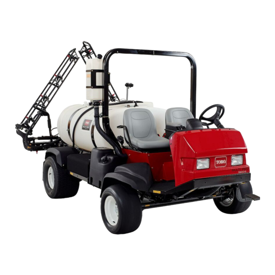
- Page 1 Form No. 3384-937 Rev A Multi-Pro 5800 Turf Sprayer Model No. 41593—Serial No. 312000001 and Up g018932 *3384-937* A Register at www.Toro.com. Original Instructions (EN)
-
Page 2: Introduction
Although Toro designs and produces safe products, you are responsible for operating the product properly and safely. You may contact Toro directly at www.Toro.com for product and accessory information, help finding a dealer, or to register your product. -
Page 3: Table Of Contents
Contents Bleeding Air from the Injectors ........39 Draining the Fuel Tank ...........39 Servicing the Fuel Filters .........39 Introduction ..............2 Electrical System Maintenance ........40 Safety ................4 Replacing the Fuses ..........40 Safe Operating Practices........... 4 Servicing the Battery..........40 Chemical Safety............4 Drive System Maintenance .........42 Before Operating ............ -
Page 4: Safety
Chemical Safety Safety WARNING Improper use or maintenance by the operator or owner can result in injury. To reduce the potential for injury, comply Chemical substances used in the spray system may with these safety instructions and always pay attention to the be hazardous and toxic to you, bystanders, animals, safety alert symbol, which means CAUTION, WARNING, or plants, soils or other property. -
Page 5: Before Operating
Before Operating – Fill the fuel tank outdoors, and fill it to about 25 mm (1 inch) below the top of the tank (the bottom of the • Operate the machine only after reading and understanding filler neck). Do not overfill it. the contents of this manual. -
Page 6: Maintenance
• – If you are ever unsure about safe operation, stop Heavy loads affect stability. Reduce the weight of the load work and ask your supervisor. and your speed when operating on hills. • Do not touch the engine or muffler while the engine is •... -
Page 7: Sound Power
Do not use open pans of fuel or flammable cleaning fluids when cleaning parts. • Do not adjust the traction control speed. To ensure safety and accuracy, have an Authorized Toro Distributor check the ground speed. • Keep your body and hands away from pin hole leaks or nozzles that eject high pressure fluid. -
Page 8: Safety And Instructional Decals
Safety and Instructional Decals Safety decals and instructions are easily visible to the operator and are located near any area of potential danger. Replace any decal that is damaged or lost. 93–6686 1. Hydraulic oil 2. Read the Operator's Manual. 107-8724 1. - Page 9 119-0567 1. Sonic boom 9. Boom lift, left boom 2. Throttle—fast 10. Boom lift, right boom 3. Headlights 11. Raise 4. Throttle—slow 12. Lower 117-4955 5. Foam marker, left boom 13. Left boom spray switch 6. Foam marker, right boom 14. Center boom spray switch 1.
- Page 10 120–0616 120-0759 1. Warning—read the Operator's Manual; use fresh, clean 1. Decrease 6. On water for first-aid washing. 2. Continuous variable 7. Mix eductor setting, spray pressure 3. Increase 8. Sonic boom 4. Rinse from clean water 9. Hazard lights tank 5.
- Page 11 120-0627 1. Cutting/dismemberment hazard, fan—stay away from moving parts, keep all guards and shields in place. 120-0624 1. Crushing/dismemberment hazard of bystanders—do not exit or enter the machine while it is moving; stop the machine before entering or exiting. 2. Falling, crushing hazard—no riders on tank; keep arms and legs inside of the vehicle at all times, use passenger hand holds.
-
Page 12: Setup
Important: This sprayer is sold without nozzles and a controller. Either a Manual Spray Operation Kit or ProControl ™ ™ ™ XPKit is necessary for the proper function of the machine. To use the sprayer, you must obtain and install nozzles . Contact your Authorized Toro Distributor for information on the available boom kit and accessories. -
Page 13: Checking The Boom Hinge Springs
Checking the Boom Hinge Springs No Parts Required Procedure Important: Operating the spray system with the boom hinge springs under the incorrect compression could damage the boom assembly. Measure the springs and use the jam nut to compress the springs to 3.96 cm (1.56 inches), if necessary. -
Page 14: Product Overview
Product Overview g018926 Figure 4 1. Passenger seat 4. Roll Over Protection 7. Pump 10. Headlight System (ROPS) 2. Fresh water tank 5. Tank lid 8. Fuel tank 3. Operator’s seat 6. Chemical tank 9. Battery g018927 Figure 5 1. Left boom 3. -
Page 15: Controls
Controls g018928 Figure 6 1. Steering wheel 4. Passenger hand hold 7. Arm rest 2. Pressure gauge 5. Storage compartment 8. Traction pedal 3. Dash controls 6. Center console 9. Brake Vehicle Controls Traction Pedal The traction pedal (Figure 7) controls the movement of the machine, both forward and reverse. - Page 16 Brake Pedal Use the brake pedal to stop or slow the sprayer (Figure 7). CAUTION If you operate the sprayer with poorly adjusted or worn brakes, you could lose control of the sprayer, resulting in serious injury or death to you or bystanders.
- Page 17 Master Boom Switch The master boom switch is located on the floor board of the machine cab and to the left of the operator. It allows you to start or stop the spray operation. Press the switch with your foot to enable or disable the spray system (Figure 12). G013747 Figure 10 1.
- Page 18 Agitation Bypass Valve The agitation bypass valve redirects the fluid flow to the pump when you turn off agitation (Figure 15). It is located at the back of the agitation valve. You can adjust this valve to ensure that pressure remains constant during agitation. Refer to Calibrating the Agitation Bypass Valve (page 27).
-
Page 19: Specifications
Wheel base 198 cm (78 inches) Optional Equipment The Toro Company has optional equipment and accessories that you can purchase separately and install on your sprayer. Contact your Authorized Service Dealer for a complete list of optional equipment that is currently available for your sprayer. -
Page 20: Operation
Operation refer to Servicing the Engine Oil (page 36) for the proper oil type and viscosity. Note: Determine the left and right sides of the machine Note: Add the oil slowly and check the level often from the normal operating position. during this process. -
Page 21: Performing Pre-Starting Checks
Filling the Fuel Tank DANGER The fuel tank capacity is approximately 40 L (10.6 US gallons). In certain conditions during fueling, static electricity can be released causing a spark which Note: The fuel tank contains a gauge which shows the fuel can ignite the fuel vapors. -
Page 22: Driving The Sprayer
for the day. Your supervisor may want you to check other 2. Press the top of the traction pedal locking switch. items on a daily basis, so ask what your responsibilities are. Note: The light on the switch illuminates. 3. Take your foot off the traction pedal. Driving the Sprayer Note: The sprayer will maintain the speed you set. -
Page 23: Filling The Fresh Water Tank
5. Start the engine, set the pump switch to the On position, and move the throttle lever to a higher idle. 6. Set the agitation switch to the On position. Important: Prior to introducing wettable powders into any Toro Spray System mix the powders in... -
Page 24: Operating The Booms
Spraying Toro recommends using the approved Eductor Kit Important: In order to ensure that your solution for this machine. Contact your Authorized Toro Dealer for more information. remains well mixed, use the agitation feature whenever you have solution in the tank. -
Page 25: Spraying Tips
• Set the engine speed as low as possible to achieve the Toro recommends using the approved rinse kit for this desired pressure and flow. This will minimize the heat machine. Contact your Authorized Toro Dealer for more generated and the air velocity from the cooling fan. -
Page 26: Calibrating The Boom Bypass Valves
system is fully clean, preventing damage to the system. 14. Clean the strainer; refer to Cleaning the Suction Strainer (page 53). Important: If you used wettable powder chemicals, clean the strainer after each tank. 15. Using a garden hose, rinse off the outside of the sprayer with clean water. -
Page 27: Calibrating The Agitation Bypass Valve
7. Record the reading on the pressure gauge. 7. Use the application rate switch to adjust the pressure on the gauge reads 689 kPa (100 psi). 8. Turn off 1 of the booms using the appropriate boom switch. 8. Turn the agitation switch to the Off position and read the pressure gauge. -
Page 28: Transporting The Sprayer
Transporting the Sprayer For moving the sprayer long distances, use a trailer. Secure the sprayer to the trailer. Also, make sure the booms are tied down and secure. Figure 27 and Figure 28 illustrate the tie-down points. Figure 27 Figure 29 1. - Page 29 3. Release the parking brake. 4. Tow the sprayer at less than 4.8 kph (3 mph). 5. When finished, close the tow valve and torque it to no more than 7 to 11 N-m (5 to 8 ft-lb).
-
Page 30: Maintenance
Maintenance Note: Determine the left and right sides of the machine from the normal operating position. Recommended Maintenance Schedule(s) Maintenance Service Maintenance Procedure Interval • Replace the hydraulic oil filter. After the first 5 hours • Torque the wheel lug nuts. •... - Page 31 Important: Refer to your engine Operator's Manual for additional maintenance procedures. Note: Looking for an Electrical Schematic or Hydraulic Schematic for your machine? Download a free copy of the schematic by visiting www.Toro.com and searching for your machine from the Manuals link on the home page.
-
Page 32: Daily Maintenance Checklist
Daily Maintenance Checklist Duplicate this page for routine use. Maintenance Check Item For the week of: Mon. Tues. Wed. Thurs. Fri. Sat. Sun. Check the brake and parking brake operation. Check the neutral lockout switch operation. Check the fuel level. Check the engine oil level. -
Page 33: Premaintenance Procedures
Grease Type: No. 2 general-purpose, lithium-base grease. 25 mm (1 inch) off the ground with the rear axle supported Toro Premium All Purpose Grease is available from your on jack stands. Toro Distributor. -
Page 34: Greasing The Boom Hinges
Figure 35 Figure 36 Three fittings inside each front wheel Right boom 1. Grease point 1. Grease fitting 3. Wipe off excess grease. Greasing the Boom Hinges 4. Repeat the procedure for each boom pivot. Service Interval: Every 100 hours Greasing the Actuator Rod Important: If the boom hinge is washed with water, Bearings... -
Page 35: Engine Maintenance
Engine Maintenance Servicing the Air Cleaner Check the air cleaner body for damage that could cause an air leak. Ensure that the dust cap is tightly sealed onto the air cleaner. Replace a damaged air cleaner body. Squeeze the valve (Figure 39) before each use to clear it of dust and debris. Service the air cleaner filter every 100 hours. -
Page 36: Servicing The Engine Oil
Preferred oil: SAE 15W40 (above 0 degrees F) • Alternate oil: SAE 10W30 or 5W30 (all temperatures) Toro Premium Engine Oil is available from your distributor in either 15W40 or 10W30 viscosity. See the Parts Catalog for part numbers. Checking the Engine Oil... - Page 37 Every 150 hours—Change the engine oil, including 8. Wipe the filter adapter gasket surface. synthetic oil (more often when operating under heavy 9. Apply a thin coat of new oil to the rubber gasket on load or in high temperature). the replacement filter.
-
Page 38: Fuel System Maintenance
Fuel System Maintenance DANGER Under certain conditions, diesel fuel and fuel vapors are highly flammable and explosive. A fire or explosion from fuel can burn you and others and can cause property damage. • Use a funnel and fill the tank outdoors, in an open area, when the engine is off and is cold. -
Page 39: Bleeding Air From The Injectors
5. Install a new standpipe assembly obtained from your The sprayer has 2 fuel filters, a fuel filter/water separator local Authorized Toro Dealer. (located between the fuel pump and the carburetor) and an Note: You may need a new grommet to secure the in-tank filter (located in the outlet tank fitting). -
Page 40: Electrical System Maintenance
Electrical System Voltage: 12 volts with 690 cold cranking Amps at 0 degrees F (-18 degrees C) Maintenance Removing the Battery Replacing the Fuses 1. Move the sprayer on a level surface, set the parking brake, stop the pump, stop the engine, and remove the The fuse block for the electrical system is located beneath ignition key. -
Page 41: Charging The Battery
Storing the Battery WARNING If the machine will be stored for more than 30 days, remove Battery terminals or metal tools could short the battery and charge it fully. Either store it on the shelf or on against metal sprayer components causing the machine. -
Page 42: Drive System Maintenance
Drive System 2. Set the parking brake, stop the pump, stop the engine, and remove the ignition key. Maintenance 3. Place a pan under the drain plugs and remove them from the wheel (Figure 49). Checking the Tire Pressure 4. Place a pan under the inner drain plug and remove it (Figure 50). -
Page 43: Adjusting The Front Wheel Toe-In
Adjusting the Front Wheel Cooling System Toe-in Maintenance Service Interval: Every 200 hours/Yearly (whichever comes first) Checking the Coolant Level The toe-in should be 0 to 3 mm (0 to 1/8 inch). Service Interval: Before each use or daily 1. Check and fill all tires; refer to Checking Tire Pressure. The cooling system is filled with a 50/50 solution of water 2. -
Page 44: Servicing The Cooling System
Important: Do not overfill the expansion tank. Important: Do not use water only or an alcohol/methanol-based coolant. 6. Install the radiator cap and the expansion tank cap. Servicing the Cooling System Service Interval: Every 100 hours—Check the cooling system hoses for wear and damage. Every 200 hours—Clean the radiator fins. -
Page 45: Brake Maintenance
Brake Maintenance Note: This usually occurs between 175 and 190 degrees F. Checking the Brakes CAUTION Service Interval: Before each use or daily As the engine continues to run, the coolant will become hot and pressurized. If you open the Before starting the sprayer, lightly press the brake pedal. -
Page 46: Belt Maintenance
Belt Maintenance Important: Ensure that you tighten both rear nuts equally so that the threaded ends of the brake cables in front of the front nuts are the same Servicing the Drive Belts length. 7. Tighten the front nuts. Service Interval: After the first 8 hours Every 100 hours Check the condition and tension of the alternator/cooling fan belt. -
Page 47: Hydraulic System Maintenance
2. Stop the pump, stop the engine, and remove the Toro Premium All Season Hydraulic Fluid (Available in ignition key. 5-gallon pails or 55-gallon drums. See parts catalog or Toro 3. Clean the area around the hydraulic-oil-tank dipstick distributor for part numbers.) cap and remove it (Figure 59). -
Page 48: Servicing The Hydraulic Oil
Service Interval: After the first 5 hours G013790 Every 400 hours/Yearly (whichever comes first) Figure 62 Use the Toro replacement filter (See your Parts Manual for the 1. Hydraulic filter 2. Rear wheels correct part number.) Important: Use of any other filter may void the warranty 3. - Page 49 Changing the Hydraulic Oil Checking the Hydraulic Lines and Hoses Service Interval: Every 400 hours/Yearly (whichever comes first) Inspect the hydraulic lines and hoses daily for leaks, kinked lines, loose mounting supports, wear, loose fittings, weather Use 56 L (15 US gallons) of the specified hydraulic fluid or deterioration and chemical deterioration.
-
Page 50: Spray System Maintenance
Warranty associated with use appropriate Personal Protective Equipment this machine. (PPE) including face and eye protection, gloves, Have an Authorized Toro Service Distributor check following or other equipment to guard against personal internal pump components for damage: contact with the chemical. -
Page 51: Inspecting The Nylon Pivot Bushings
Inspecting the Nylon Pivot 5. Use a wrench on the flat sides of the actuator rod to immobilize it then loosen the jam nut to allow for the Bushings eyelet rod to be manipulated (Figure 65). Service Interval: Every 400 hours/Yearly (whichever comes first) 1. -
Page 52: Inspecting The Tank Straps
Inspecting the Tank Straps Service Interval: Before each use or daily—Check the tank straps. Once the main tank has been filled with water, check to see if there is any play in the tank straps. If the straps are loose, tighten the fasteners at the top straps until they are flush with tank. -
Page 53: Flow Diagram
Flow Diagram g018931 Figure 67 Cleaning 2. Remove the retainer from the red fitting attached to the large hose on the top of the tank (Figure 68). Cleaning the Suction Strainer Service Interval: Before each use or daily 1. Position the sprayer on a level surface, set the parking brake, stop the pump, stop the engine, and remove the ignition key. -
Page 54: Storage
Storage 1. Position the sprayer on a level surface, set the parking brake, stop the pump, stop the engine, and remove the ignition key. 2. Clean dirt and grime from the entire machine, including the outside of the engine's cylinder head fins and blower housing. - Page 55 D. Using a 3 mm Allen wrench, remove the screws temperatures below 32 degrees F (0 degrees C). A securing the piston assemblies in the valve fully charged battery maintains its charge for about assembly. Make sure to account for the springs 50 days at temperatures lower than 40 degrees F (4 in the valve (Figure 70).
-
Page 56: Troubleshooting
Troubleshooting Troubleshooting the Engine and Vehicle Problem Possible Cause Corrective Action The starter does not crank. 1. The electrical connections are corroded 1. Check the electrical connections for or loose. good contact. 2. A fuse is blown or loose. 2. Correct or replace fuse. 3. - Page 57 Problem Possible Cause Corrective Action The engine loses power. 1. The crankcase oil level is incorrect. 1. Fill or drain to the Full mark. 2. The air cleaner element is dirty. 2. Clean or replace. 3. Dirt, water, or stale fuel is in the fuel 3.
- Page 58 Problem Possible Cause Corrective Action A boom actuator is not operating properly. 1. A thermal breaker in the fuse block 1. Wait for the system to cool down before responsible for powering the actuator resuming operation. If the thermal has tripped due to overheating. breakers trip repeatedly, contact your Authorized Service Dealer.
- Page 59 Notes:...
- Page 60 Countries Other than the United States or Canada Customers who have purchased Toro products exported from the United States or Canada should contact their Toro Distributor (Dealer) to obtain guarantee policies for your country, province, or state. If for any reason you are dissatisfied with your Distributor's service or have difficulty obtaining guarantee information, contact the Toro importer.