Table of Contents
Advertisement
FORM NO. 3324-616 Rev A
OPERATOR'S
0001
MODEL NO. 30581—8
& UP
MANUAL
®
®
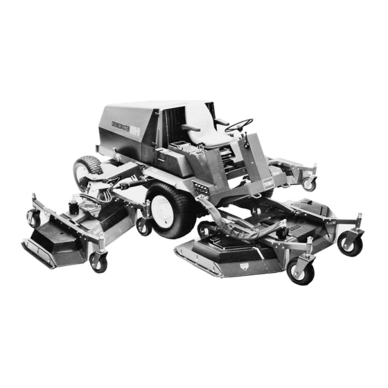
GROUNDSMASTER
580-D
To understand this product, and for safety
and optimum performance, read this
manual before starting operation. Pay
special attention to SAFETY
INSTRUCTIONS highlighted by this
symbol.
© The TORO Company 1999
Advertisement
Table of Contents

Related Manuals for Toro GROUNDSMASTER 580-D 30581


Summary of Contents for Toro GROUNDSMASTER 580-D 30581
- Page 1 MODEL NO. 30581—8 & UP MANUAL ® ® GROUNDSMASTER 580-D To understand this product, and for safety and optimum performance, read this manual before starting operation. Pay special attention to SAFETY INSTRUCTIONS highlighted by this symbol. © The TORO Company 1999...
-
Page 2: Table Of Contents
Whenever you have questions or need service, contact your local authorized Toro Distributor. In addition to having a complete line of accessories and professional turf care service technicians, the distributor has a complete line of genuine TORO replacement parts to keep your machine operating properly. -
Page 3: Safety Instructions
Safety Instructions Training • Store fuel in containers specifically designed for this purpose. Read the instructions carefully. Be familiar with the • Refuel outdoors only and do not smoke while controls and the proper use of the equipment. refueling. • Add fuel before starting the engine. -
Page 4: Maintenance And Storage
Safety Instructions • never mow across the face of the slope, unless lawn mower; the lawn mower is designed for this purpose. • after striking a foreign object. Inspect the lawn mower for damage and make repairs before 6. Use care when pulling loads or using heavy restarting and operating the equipment. - Page 5 Safety Instructions Vibration Levels This unit has a vibration level of 2.5 m/s at the posterior, based on measurements of identical machines per ISO 5349 procedures. This unit does not exceed a vibration level of 0.5 m/s the posterior based on measurements of identical machines per ISO 2631 procedures.
-
Page 6: Symbol Glossary
Symbol Glossary Caustic liquids, Poisonous Electrical shock, High pressure High pressure High pressure Crushing of Crushing of chemical burns to fumes or toxic electrocution fluid, injection spray, erosion of spray, erosion of fingers or hand, toes or foot, force fingers or hand gases, asphyxiation into body flesh... - Page 7 Safety Instructions Consult technical Fasten seat Safety alert Outline safety Read operator’s Fire, open light Eye protection manual for proper belts triangle alert symbol manual and smoking must be worn service prohibited procedures Head protection Hearing Caution, toxic First aid Flush with water Engine Transmission Hydraulic system...
- Page 8 Symbol Glossary, continued n/min Engine start Engine stop Engine failure/ Engine rotational Choke Primer (start aid) Electrical preheat Transmission malfunction speed/frequency (low temperature start aid) N H L F Transmission Transmission Transmission Clutch Neutral High Forward oil pressure oil temperature failure/malfunction Reverse Hydraulic oil...
-
Page 9: Specifications
Specifications CUTTING UNITS OUTBOARD CUTTING UNITS Cutting Unit Drive System: All hydraulic drive. Initial Type: Two, three-spindle, side-mounted rotary cutting cutting drive engagement via electric switch. Drive shuts off units, each with a 145 cm width of cut. or engages individually as cutting units are raised or lowered. - Page 10 Specifications Leaf Mulcher Cold Start Kit Foam Filled Castor Tires Extra Traction Drive TireSpecifications and design subject to change without notice.
-
Page 11: Before Operating
Before Operating When the batteries are fully charged, disconnect the CAUTION charger from the electrical outlet and battery posts. Wear safety goggles and rubber gloves when working Install the negative (–) cable ends, slide the tray with the batteries. Charge batteries in a well-ventilated back in place, secure it with capscrews and install place so the gases produced while charging can dissipate. -
Page 12: Check The Cooling System
Before Operating CHECK THE COOLING SYSTEM (DAILY) The cooling system is filled with a 50/50 solution of water and permanent ethylene glycol anti-freeze. Check the coolant level at the beginning of each day before starting the engine. Capacity of the cooling system is 14.7 L. CAUTION Figure 3 The best time to check the coolant level is each day... - Page 13 Before Operating CHECK HYDRAULIC SYSTEM FLUID (DAILY) Fluid level should be checked daily through the sight glass at the rear of the hydraulic reservoir (Fig. 6). When oil is cold, the level will be slightly below center, but it should be in the middle of the sight glass when the oil is warm.
-
Page 14: Adjusting Height Of Cut
Before Operating Position all castor arm height-of-cut spacers to on the underside of the castor arms. Do not move washers. Leave them in their original position. Note: Unless all castor wheel axles are not in the same location, axles do not have to be relocated. All, however, must be in the same holes (Fig. - Page 15 Before Operating Remove the castor fork shaft and spacer assembly from the castor arm (Fig. 10). Place spacers onto the castor spindle to the desired height-of-cut setting and install the castor fork shaft in arm (Fig. 9). Install the remaining spacers onto the shaft and secure the assemblies with the lynch pin (Fig.
-
Page 16: Controls
Controls Seat (Fig. 12)—Pull the seat adjusting lever (right side) Hour Meter (Fig. 13)—Registers accumulated hours of outward, slide the seat fore or aft to the desired position and engine operation, which is useful for determining intervals release the lever to lock the seat in position. The seat moves for service maintenance and lubrication. - Page 17 Controls Hydraulic Oil Filter Warning (Fig. 14)—A warning angle. Pivot the lever forward to lock the steering column indicator light and audible signal warn the filter is clogged and wheel in the desired position. and needs service. Key Switch (Fig. 16)—Three positions: OFF, ON and Hydraulic Oil Level Warning (Fig.
- Page 18 Controls Cutting Unit Lift Controls (Fig. 16)—The two outside corrected. levers raise and lower the outside cutting units; the center lever raises and lowers the front unit. The engine must be running to lower and raise cutting units. Cutting unit blades automatically stop whenever the cutting units are raised.
- Page 19 Controls Figure 19 1. Traction pedal 2. Brake pedal 3. Steering/parking brake pedals 4. Brake latch lever Brake Pedal (Fig. 19)—A pedal operated by the right foot actuates fully enclosed, multiple-disc front brakes. Note: There is dynamic braking through the closed-loop hydrostatic traction drive system.
-
Page 20: Operating Instructions
Operation IMPORTANT. The fuel system must be bled if any of engine starts and allow it to return to the RUN position. the following have occurred: A. Initial start-up of a new machine. Note: Do not run the starter motor more than 10 seconds at a time or premature starter failure may B. -
Page 21: Diagnostic Light
Operation Figure 24 1. Fuel filter air bleed plug Figure 22 1. Engine hood Loosen the air vent plug on the injection pump 2. Left side panel 3. Glow plug indicator light about 1-1/2 turns (Fig. 25). Operate the priming 4. - Page 22 Operation relays must be connected and functioning properly. The Diagnostic ACE display is a tool to help the user verify the correct electrical functions of the machine. CHECKING INTERLOCK SWITCHES The purpose of the interlock switches is to prevent the engine from cranking or starting, unless the traction pedal is Figure 26 in NEUTRAL, to ensure the cutting units disengage when...
- Page 23 Operation pedal, etc.), and note that the appropriate LED on Diagnostic ACE will blink on and off when corresponding switch is closed and opened. Repeat on each switch that it is possible to be changed by hand. If the switch is closed and appropriate LED does not blink on and off, check all wiring and connections to the switch and/or check switches with an ohmmeter.
- Page 24 LEDs are not correctly illuminated, this indicates an ECU problem. If this occurs, IMPORTANT: Do not push or tow the machine faster contact your Toro distributor for assistance. than 3–4.8 km/hr because internal transmission damage...
- Page 25 Operation may occur. The by-pass valve must be open whenever now unlocked. the machine is pushed or towed by this method. TORO does not recommend this process be used as standard Lock the wheel hubs immediately after completing procedure. towing operations. Remove the covers and reinstall...
- Page 26 (if used), move the PTO switch to DISENGAGE and release it (the switch returns to neutral), then fully raise the cutting units. High-Range Ground Speed Operation—Toro recommends HIGH RANGE ground speed operation be performed only on roads with the cutting units in fully raised position.
-
Page 27: Maintenance
Maintenance Maintenance LUBRICATION The following must be lubricated regularly with No. 2 general purpose lithium or molybdenum base grease. The chart below lists service intervals based upon normal operating conditions. However, lubricate more frequently under extreme conditions. The left column numbers correspond with numbers in Fig. 31. Component No. - Page 28 Maintenance Figure 31 Figure 31...
-
Page 29: Engine Oil And Filter
Maintenance DAILY MAINTENANCE CHECKLIST Hydraulic Hoses for Damage Safety Interlock Operation Fluid Leaks Brake Operation Tire Pressure Engine Oil Level Instrument Operation Cooling System Fluid Level Condition of Blades Drain Water/Fuel Separator Lubricate All Grease Fittings2 Air Filter/Pre-Cleaner Condition Touch-up Damaged Paint Radiator &... -
Page 30: Maintenance Schedule
Maintenance Maintenance Schedule Maintenance Procedure Maintenance Interval & Service Lubricate All Grease Fittings Every Every Every Every Every Inspect Air Filter, Dust Cup, and Baffle Clean Under Cutting Unit Belt Covers hours hours hours hours hours Check Cutting Unit Drive Belt Adjustment ‡Change Engine Oil and Replace Filter Check Fan and Alternator Belt Tension... -
Page 31: Engine Fuel System
Maintenance Figure 33 1. Dipstick Figure 35 1. Engine oil drain plug Remove the drain plug and allow oil to drain into the pan. Remove and replace the oil filter (Fig. 36); refer to the parts catalog for the replacement number. -
Page 32: Engine Cooling System
Maintenance ENGINE COOLING SYSTEM The cooling system holds approximately 14.7 L of a 50/50 solution of ethylene glycol anti-freeze and water. To properly maintain the system, use the following procedures: Check coolant level each day before starting the engine; refer to Check Cooling System in Before Operating section. - Page 33 Maintenance A. Use procedures instep 2, items a-c. needed. Check and adjust tension as follows: B. Unlatch the latch handles on both sides and A. Unlatch and raise the hood and prop it open. remove the radiator cowl and grille support Unlatch and remove the right side panel.
-
Page 34: Servicing The Air Cleaner
Maintenance SERVICING THE AIR CLEANER Washing Method A. Prepare a solution of filter cleaner and water Release the latches securing the air cleaner cover to and soak the filter element about 15 minutes. the air cleaner body. Separate the cover from the Refer to directions on the filter cleaner carton body. - Page 35 After 50 hours initial operation, replace the hydraulic filter and cause injury. Fluid accidentally injected into your (Toro Part No. 69-1720). skin must be surgically removed within a few hours by a doctor familiar with this form of injury or gangrene Place drain pan under filter and remove filter...
-
Page 36: Drain Water From Hydraulic Reservoir
flushed. Contact your local The test ports (Fig. 49) are used for testing the hydraulic TORO distributor for assistance. circuits. Contact your local TORO distributor for assistance on use of these components. Place the drain pan under the reservoir. In turn, remove all three (3) drain plugs and let the oil drain into pan (Fig. -
Page 37: Battery Service
Clean the batteries with a solution of baking soda and water, then rinse with clear water. To prevent corrosion, coat the battery posts and cable connectors with Grafo 112X (Skin-over) grease, TORO Part No. 505-47. CAUTION Wear safety goggles and rubber gloves when working with the batteries. - Page 38 Maintenance Remove the capscrews securing the battery tray to the machine and slide the tray out (Fig. 51). Check both batteries for charge with a hydrometer. If the batteries check acceptably, slide the tray back in place, secure with capscrews and install the side panel.
-
Page 39: Wheels And Tires
Maintenance CUTTING UNIT LUBRICATION Follow guidelines in the Lubrication Chart to properly maintain the units. To gain access to the center and inner spindle shaft fittings on each outboard unit, proceed as follows: Note: To grease spindle bearings, apply 2–3 pumps with a hand grease gun for each spindle. - Page 40 Maintenance the engine and remove the key from the ignition switch. Fit the deck tilt link over the weldment on the right side of the traction unit and secure with a klik pin. Position a link so it clears when the cutting unit is raised.
-
Page 41: Removing The Cutting Unit
Remove blade bolt, lockwasher, anti-scalp cup and blade from spindle assembly (Fig. 59). Do not try to straighten a bent blade. Never weld a broken or cracked blade. Always use a new TORO blade to assure continued safety certification of the product. Figure 60 1. - Page 42 Maintenance loaded idlers and normally do not require tensioning. CAUTION Position the machine on level surface, lower the If the blade is allowed to wear, a slot will form cutting unit to the shop floor, engage the parking between the sail and flat part of the blade (Fig. brake, shut the engine off and remove the key from 60C)).
- Page 43 Maintenance compression spring (Fig. 62) will be approximately 11.3 Front Cutting Unit Note: To remove the center section belt, wing spindle drive Tighten jam nuts to secure adjustment. Replace the belts must first be removed. covers. Remove deck covers. Lift each wing to release the idler pulley tension and slip the belt off the pulleys.
- Page 44 Maintenance Remove belt(s). Position the new belt(s) in pulleys and assemble the gear box and plate assembly to the deck. Adjust belt tension; refer to Adjusting Cutting Unit Belt Tension. SEPARATING CUTTING UNITS FROM TRACTION UNIT Front Cutting Unit Figure 66 1.
- Page 45 Maintenance recommended standards, add shims between the cutting deck and spindle housing; proceed to step 6. If the measurements meet standards, proceed to step Rotate the blades so the tips lineup with one another. Tips of adjacent blades must be within 3 mm of each other.
-
Page 46: Traction Control Neutral Adjustment
OFF authorized TORO Distributor for assistance. Actuate the pump lever (with the foot pedal) to make sure that the foot pedal and linkage operate TRACTION (NEUTRAL) SWITCH freely. -
Page 47: Identification And Ordering
(Fig. 72). Disconnect the ball joint from the traction pedal. To order parts from an authorized TORO Distributor, please provide: Model and serial numbers of the component in question.