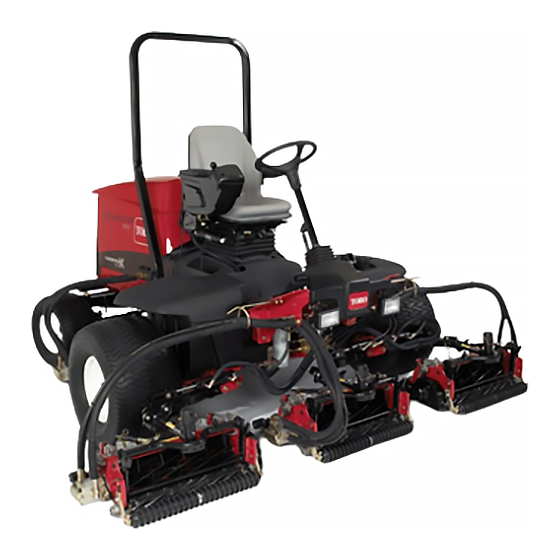
Toro Reelmaster 5410 Operator's Manual
Traction unit
Hide thumbs
Also See for Reelmaster 5410:
- Service manual (662 pages) ,
- Operator's manual (60 pages) ,
- Operation manual (20 pages)

Related Manuals for Toro Reelmaster 5410


Summary of Contents for Toro Reelmaster 5410
- Page 1 Form No. 3424-342 Rev A Reelmaster ® 5410 and 5510 Traction Unit Model No. 03675—Serial No. 403280001 and Up Model No. 03676—Serial No. 403280001 and Up *3424-342* A Register at www.Toro.com. Original Instructions (EN)
- Page 2 Authorized Service specific Declaration of Conformity (DOC) sheet. Dealer or Toro Customer Service and have the model and serial numbers of your product ready. Figure 2 It is a violation of California Public Resource Code...
-
Page 3: Table Of Contents
Contents Fuses..............42 Drive System Maintenance ........42 Checking the Torque of the Wheel Safety ............... 4 Nuts .............. 42 General Safety........... 4 Adjusting the Traction Drive for Neutral ..... 42 Safety and Instructional Decals ......5 Adjusting the Rear Wheel Toe-in....... 43 Setup .............. -
Page 4: Safety
Safety This machine has been designed in accordance with EN ISO 5395:2017 (when appropriate decals are applied) and ANSI B71.4-2017. General Safety This product is capable of amputating hands and feet and of throwing objects. Using this product for purposes other than its intended use could prove dangerous to you and bystanders. -
Page 5: Safety And Instructional Decals
Safety and Instructional Decals Safety decals and instructions are easily visible to the operator and are located near any area of potential danger. Replace any decal that is damaged or lost. decal133-8062 133-8062 decal106-6755 106-6755 decal93-6689 1. Engine coolant under 3. - Page 6 decal110-9642 110-9642 1. Stored energy hazard—read the Operator's Manual. decalbatterysymbols Battery Symbols 2. Move the cotter pin to the hole closest to the rod bracket and then remove the lift arm and pivot yoke. Some or all of these symbols are on your battery 1.
- Page 7 decal121-5644 121–5644 1. Light switch 6. Slow 2. Engage 7. Lower 3. Power take-off 8. Raise 4. Disengage 9. Read the Operator’s Manual. 5. Fast...
- Page 8 decal133-2930 133-2930 1. Warning—do not operate this machine unless you are trained. 4. Tipping hazard—drive slowly when turning; do not turn sharply while traveling fast; only drive on slopes with the cutting units lowered; always wear a seatbelt. 2. Warning—wear hearing protection. 5.
- Page 9 decal125-8753 125-8753 1. Read the Operator's Manual for more maintenance information.
-
Page 10: Setup
Setup Loose Parts Use the chart below to verify that all parts have been shipped. Procedure Description Qty. – No parts required Adjust the tire pressure. – No parts required Adjust the control-arm position. Right front hose guide Install the cutting units. Left front hose guide –... -
Page 11: Adjusting The Control-Arm Position
Adjusting the Control-Arm Installing the Cutting Units Position Parts needed for this procedure: Right front hose guide No Parts Required Left front hose guide Procedure Procedure The control-arm position can be adjusted for the Remove the reel motors from the shipping operators comfort. - Page 12 install the hose guides to the front of the cutting-unit tabs (Figure 8). The hose guides should lean toward the center cutting unit (Figure 8 Figure g003949 Figure 5 1. Turf-compensation spring 3. Spring tube 2. Rod bracket g014684 Figure 7 Remove the flange nut securing the spring-tube bolt to the carrier-frame tab (Figure...
- Page 13 Note: When installing or removing the slide the lift-arm-pivot shaft out of the lift cutting units, make sure the hairpin cotter is (Figure 12). installed in the spring rod hole next to the rod bracket. Otherwise, the hairpin cotter must be installed in the hole in the end of the rod.
-
Page 14: Adjusting The Turf-Compensation Spring
Tighten the hex nuts on the front end of the spring rod until the compressed length of the spring is 12.7 cm (5 inches) on Reelmaster 5410 (5-inch cutting units) or 15.9 cm (6.25 inches) on Reelmaster 5510 (7-inch cutting units); refer... -
Page 15: Installing The Ce Hood Latch
Outside the hood, insert the hook end of the latch through the hole in the hood. Make sure that the rubber sealing washer remains to the outer side of the hood (Figure 17). Installing the CE Hood Inside the hood, insert the metal washer onto the latch and secure with the nut. -
Page 16: Product Overview
Product Overview g003945 Figure 20 g004144 Figure 19 1. Engine hood 5. Seat adjustments 2. Operator's seat 6. Front cutting units 1. Chain bracket 3. Cutting-unit kickstand 3. Control arm 7. Rear cutting units 2. Snapper pin 4. Steering wheel Controls Seat-Adjusting Knobs The seat-adjusting lever... -
Page 17: Traction Pedal
Traction Pedal Brake Pedal The traction pedal (Figure 22) controls the forward Press the brake pedal (Figure 22) to stop the machine. and reverse operation. Press the top of the pedal to move the machine forward and the bottom to move Parking Brake the machine backward. -
Page 18: Headlight Switch
Headlight Switch Pivot the switch downward to turn on the headlights (Figure 23). Enable/Disable Switch Use the enable/disable switch (Figure 23) in conjunction with the lower mow/raise control lever to operate the cutting units. Backlap Levers g004132 Figure 25 Use the backlap levers in conjunction with the lower mow/raise control lever for backlapping the reels 1. - Page 19 InfoCenter Icon Description (cont'd.) Lower the cutting units. Sit in the seat. The parking brake is On. The range is high (transport). Neutral g020650 Figure 27 The range is low (mow). 1. Indicator light 3. Middle button 2. Right button 4.
- Page 20 InfoCenter Icon Description (cont'd.) Release the switch. Change to the indicated state. Symbols are often combined to form sentences. Some examples are shown below Put the machine into Neutral. Engine start is denied. Engine shutdown Engine coolant is too hot. Sit down or set the parking brake...
- Page 21 The Faults menu contains a list InfoCenter. The menu choices of the recent machine faults. are English or Metric. Refer to the Service Manual or contact your Toro Distributor Language Controls the language used on the InfoCenter*. for more information on...
- Page 22 Protect Settings to O , set the passcode, and InfoCenter Revision Lists the software revision of turn the key in the ignition switch to the O the InfoCenter. position and then to the O position. CAN Bus Lists the machine communication bus status.
-
Page 23: Specifications
0–13 km/h (0–8 mph) Attachments/Accessories A selection of Toro approved attachments and accessories is available for use with the machine to enhance and expand its capabilities. Contact your Authorized Service Dealer or Distributor or go to www.Toro.com for a list of all approved attachments and accessories. -
Page 24: Before Operation
Performing Daily Operation Maintenance Note: Determine the left and right sides of the machine from the normal operating position. Service Interval: Before each use or daily Before starting the machine each day, perform the Before Operation Each Use/Daily procedures listed in Maintenance (page 33). -
Page 25: During Operation
Fuel filter plugging may be expected for a time after converting to biodiesel blends. During Operation Safety • Contact your Authorized Toro Distributor if you wish for more information on biodiesel. General Safety • The owner/operator can prevent and is responsible for accidents that may cause personal injury or property damage. - Page 26 • Do not carry passengers on the machine and injury or death. You are responsible for safe slope keep bystanders and pets away from the machine operation. Operating the machine on any slope during operation. requires extra caution. • Operate the machine only in good visibility to avoid •...
-
Page 27: Starting And Stopping The Engine
Starting and Stopping the counterbalance on the cutting unit by 2.3 kg (5 lb). You can position the springs on the back side of the Engine first spring actuator to remove all counter balance (fourth position). Important: You must bleed the fuel system before Position the machine on a level surface, lower starting the engine if you are starting the engine the cutting units, stop the engine, engage the... -
Page 28: Setting The Reel Speed
g027937 Figure 30 1. Switch 2. Lift-arm sensing device Tighten the mounting screws. Setting the Reel Speed To achieve a consistent, high quality of cut and a uniform after cut appearance, it is important that you set the reel speed to the proper setting. Adjust the reel speed as follows: In the InfoCenter, under the settings menu, enter the blade count, mow speed and HOC to calculate the proper reel speed. -
Page 29: Understanding The Diagnostic Light
g031996 Figure 32 7 inch (177.8 mm) Reel Speed Chart Understanding the Checking the Interlock Diagnostic Light Switches The machine is equipped with a diagnostic light The purpose of the interlock switches is to prevent the which indicates if the electronic controller senses an engine from cranking or starting unless the traction electronic malfunction. -
Page 30: Hydraulic Valve Solenoid Functions
Turn the key in the ignition switch to the O Solenoid Function position, but do not start the machine. MSV2 Front reel circuit Locate the appropriate switch function in the MSV1 Rear reel circuit diagnostics menu on the InfoCenter. SVRV Lift/lower cutting units Individually, change each of the switches from Lift/lower front cutting unit... -
Page 31: After Operation
After Operation After Operation Safety General Safety • Always shut off the engine, remove the key (if equipped), wait for all moving parts to stop, and allow the machine to cool before adjusting, servicing, cleaning, or storing the machine. • Clean grass and debris from the cutting units, drives, mufflers, cooling screens, and engine compartment to help prevent fires. -
Page 32: Locating The Jacking Points
Locating the Jacking Points Note: Use jack stands to support the machine when required. • Front—rectangular pad, under the axle tube, inside each front tire (Figure 35). g031850 Figure 35 1. Front jacking point • Rear—rectangular axle tube on the rear axle... -
Page 33: Maintenance
• To ensure safe, optimal performance of the – Shut off the engine and remove the key. machine, use only genuine Toro replacement – Wait for all moving parts to stop. parts. Replacement parts made by other – Allow machine components to cool before manufacturers could be dangerous, and such use performing maintenance. - Page 34 Maintenance Service Maintenance Procedure Interval • Service the air cleaner. (Service the air cleaner earlier if the air cleaner indicator shows red. Service it more frequently in extremely dirty or dusty conditions.) • Check the fuel lines and connections for deterioration, damage, or loose Every 400 hours connections.
-
Page 35: Daily Maintenance Checklist
Date Information Important: Refer to your engine operator’s manual for additional maintenance procedures. Note: Download a free copy of the electrical or hydraulic schematic by visiting www.Toro.com and searching for your machine from the Manuals link on the home page. -
Page 36: Lubrication
Lubrication • Lift-arm pivots (1 each) (Figure • Cutting-unit carrier-frame and pivot (2 each) (Figure Greasing the Bearings and Bushings Service Interval: Every 50 hours (and immediately after every washing). Lubricate all grease fittings for the bearings and bushings after with No. 2 lithium grease. The grease fitting locations and quantities are as follows: •... -
Page 37: Engine Maintenance
• Alternate oil: SAE 10W-30 or 5W-30 (all temperatures) g003966 Figure 42 Toro Premium Engine oil is available from your distributor in either 15W-40 or 10W-30 viscosity. • Brake pedal (1) (Figure Park the machine on a level surface, stop the engine, set the parking brake, and remove the key from the ignition switch. -
Page 38: Servicing The Air Cleaner
limits on the oil gauge. Engine failure may occur as a result of overfilling or underfilling the engine oil. Install the oil-fill cap and close the hood. Servicing the Air Cleaner Service Interval: Every 400 hours (Service the air cleaner earlier if the air cleaner indicator shows red. -
Page 39: Servicing The Engine Oil And Filter
Servicing the Engine Oil Note: This cleaning process prevents debris from migrating into the intake when the filter is and Filter removed. Remove and replace the filter (Figure 47). Service Interval: After the first 50 hours—Change the engine oil and filter. Note: Cleaning of the used element is not recommended due to the possibility of damage... -
Page 40: Adjusting The Throttle
Fuel System rubber gasket contacts the filter adapter, then tighten the filter an additional 1/2 turn. Maintenance Important: Do not over-tighten the filter. Add oil to the crankcase; refer to Checking the DANGER Engine-Oil Level (page 37). Under certain conditions, diesel fuel and fuel vapors are highly flammable and explosive. -
Page 41: Cleaning The Fuel Pick-Up Tube Screen
Electrical System Maintenance Important: Before welding on the machine, disconnect both cables from the battery, both wire-harness plugs from the electronic control module, and the terminal connector from the alternator to prevent damage to the electrical system. Electrical System Safety g007367 Figure 51 •... -
Page 42: Fuses
Drive System WARNING Charging the battery produces gasses that Maintenance can explode. Never smoke near the battery and keep sparks Checking the Torque of the and flames away from it. Wheel Nuts Keep the terminals and the entire battery case clean because a dirty battery will discharge slowly. -
Page 43: Adjusting The Rear Wheel Toe-In
g004136 Figure 55 1. Jam nut 3. Wrench slot 2. Tie rod g004147 Figure 54 1. Locknut 2. Traction-adjustment cam Using the wrench slot, rotate the tie rod. Measure the distance at the front and rear of the rear wheels at axle height. WARNING Note: The distance at the front of the rear... -
Page 44: Cooling System Maintenance
Cooling System Maintenance Cooling System Safety • Swallowing engine coolant can cause poisoning; keep out of reach from children and pets. • Discharge of hot, pressurized coolant or touching a hot radiator and surrounding parts can cause severe burns. – Always allow the engine to cool at least 15 minutes before removing the radiator cap. - Page 45 g004138 g004137 Figure 57 Figure 59 1. Rear-screen latch 2. Rear screen 1. Radiator Thoroughly clean the screen thoroughly with Pivot the oil cooler back into position and secure compressed air. the latches. Pivot the latches inward to release the oil cooler Close the screen and secure the latch.
-
Page 46: Brake Maintenance
Brake Maintenance Note: Ensure that the cable conduit does not rotate during the tightening procedure. Adjusting the Parking Adjusting the Brakes Parking-Brake Latch Adjust the brakes when there is more than 2.5 cm (1 If the parking brake fails to engage and latch, an inch) of free travel (Figure 60) of the brake pedal, or... -
Page 47: Belt Maintenance
Belt Maintenance Hydraulic System Maintenance Check the condition and tension of the alternator belt after the first day of operation and every 100 operating hours thereafter. Hydraulic System Safety Tensioning the Alternator • Seek immediate medical attention if fluid is injected into skin. -
Page 48: Checking The Hydraulic-Fluid Level
Toro Premium All Season Hydraulic Fluid (Available in 19 L (5 US gallon) pails or 208 L (55 US gallon) drums. See the Parts Catalog or your Toro Distributor for part numbers.) Alternative fluids: If the Toro fluid is not available,... -
Page 49: Replacing The Hydraulic Filters
Replacing the Hydraulic Place a large drain pan under the fitting secured to the bottom of the hydraulic-fluid reservoir Filters (Figure 65). Service Interval: Every 800 hours (Or more often if the service-interval indicator is in the red zone). The hydraulic system is equipped with a service-interval indicator (Figure 66). -
Page 50: Checking The Hydraulic Lines And Hoses
Use the hydraulic system test ports to test the 1/2 turn. pressure in the hydraulic circuits. Contact your Toro Distributor for assistance. Repeat the procedure on the other filter. Use the test ports on the front hydraulic tubes... -
Page 51: Cutting Unit System Maintenance
Cutting Unit System Maintenance Blade Safety • A worn or damaged blade or bedknife can break, and a piece could be thrown toward you or bystanders, resulting in serious personal injury or death. • Inspect the cutting units periodically for excessive wear or damage. - Page 52 Make initial reel-to-bedknife adjustments appropriate for backlapping on all cutting units which are to be backlapped; refer to the cutting unit Operator's Manual. Start the engine and run at low idle speed. DANGER Changing the engine speed while backlapping may cause the reels to stall. •...
-
Page 53: Storage
Clean the battery, terminals, and posts with a wire brush and baking soda solution. Coat the cable terminals and battery posts with Grafo 112X skin-over grease (Toro Part Number 505-47) or petroleum jelly to prevent corrosion. Slowly recharge the battery every 60 days for 24 hours to prevent lead sulfation of the battery. - Page 54 The Toro Company (“Toro”) respects your privacy. When you purchase our products, we may collect certain personal information about you, either directly from you or through your local Toro company or dealer. Toro uses this information to fulfil contractual obligations - such as to register your warranty, process your warranty claim or to contact you in the event of a product recall - and for legitimate business purposes - such as to gauge customer satisfaction, improve our products or provide you with product information which may be of interest.
- Page 55 While the exposure from Toro products may be negligible or well within the “no significant risk” range, out of an abundance of caution, Toro has elected to provide the Prop 65 warnings. Moreover, if Toro does not provide these warnings, it could be sued by the State of California or by private parties seeking to enforce Prop 65 and subject to substantial penalties.
- Page 56 Countries Other than the United States or Canada Customers who have purchased Toro products exported from the United States or Canada should contact their Toro Distributor (Dealer) to obtain guarantee policies for your country, province, or state. If for any reason you are dissatisfied with your Distributor's service or have difficulty obtaining guarantee information, contact the Toro importer.