Table of Contents
Advertisement
Manuals by Motomatrix / www.motomatrix.co.uk / The Solution For Lost Motorcycle Coded Keys.
TYPE CODE
• Throughout this manual, the following abbreviations are used to identify individual model.
CODE
AREA TYPE
E
U.K, Ireland
F
France, Belgium
EUROPEAN DIRECT SALES
(Spain, Holland, Austria, Portugal, Belgium, Denmark, Greece, Italy, Macedonia,
ED
Romania, Burgaria, Ukuraine, Israel, Finland, Germany, Sweden, Island, Russia,
Poland, Slovenia, Croatia, Latvia, Norway, Swiss, Luxemburug, Hungary, Czech,
Slovakia)
III ED
Germany
email: info@motomatrix.co.uk
Advertisement
Chapters
Table of Contents
Troubleshooting

Related Manuals for Honda CBF600SA


Summary of Contents for Honda CBF600SA
- Page 1 Manuals by Motomatrix / www.motomatrix.co.uk / The Solution For Lost Motorcycle Coded Keys. TYPE CODE • Throughout this manual, the following abbreviations are used to identify individual model. CODE AREA TYPE U.K, Ireland France, Belgium EUROPEAN DIRECT SALES (Spain, Holland, Austria, Portugal, Belgium, Denmark, Greece, Italy, Macedonia, Romania, Burgaria, Ukuraine, Israel, Finland, Germany, Sweden, Island, Russia, Poland, Slovenia, Croatia, Latvia, Norway, Swiss, Luxemburug, Hungary, Czech, Slovakia)
- Page 2 Any person who intends to use a replacement part, service procedure or a tool that is not recommended by Honda, must determine the risks to their personal safety and the safe operation of the vehicle.
-
Page 3: How To Use This Manual
OUT INCURRING ANY OBLIGATION WHATSO- EVER. NO PART OF THIS PUBLICATION MAY BE REPRODUCED WITHOUT WRITTEN PER- MISSION. THIS MANUAL IS WRITTEN FOR PERSONS WHO HAVE ACQUIRED BASIC KNOWLEDGE OF MAINTENANCE ON HONDA MOTORCYCLES, MOTOR SCOOTERS ATVS. Honda Motor Co., Ltd. - Page 4 ® Example: Molykote G-n Paste manufactured by Dow Corning U.S.A. Honda Moly 60 (U.S.A. only) Rocol ASP manufactured by Rocol Limited, U.K. Rocol Paste manufactured by Sumico Lubricant, Japan Use silicone grease. Apply a locking agent. Use a middle strength locking agent unless otherwise specified.
-
Page 5: Table Of Contents
Manuals by Motomatrix / www.motomatrix.co.uk / The Solution For Lost Motorcycle Coded Keys. 1. GENERAL INFORMATION SERVICE RULES ········································· 1-2 FRONT WHEEL/SUSPENSION/STEERING SPECIFICATIONS ····································· 1-11 MODEL IDENTIFICATION··························· 1-3 REAR WHEEL/SUSPENSION SPECIFICATIONS ····································· 1-11 GENERAL SPECIFICATIONS······················ 1-6 HYDRAULIC BRAKE SPECIFICATIONS··· 1-12 LUBRICATION SYSTEM SPECIFICATIONS········································... -
Page 6: Service Rules
SERVICE RULES GENERAL INFORMATION 1. Use genuine Honda or Honda-recommended parts and lubricants or their equivalents. Parts that don't meet Honda's design specifications may cause damage to the motorcycle. 2. Use the special tools designed for this product to avoid damage and incorrect assembly. -
Page 7: Model Identification
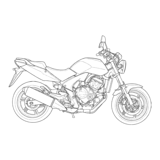
Manuals by Motomatrix / www.motomatrix.co.uk / The Solution For Lost Motorcycle Coded Keys. GENERAL INFORMATION MODEL IDENTIFICATION CBF600SA shown: CBF600N shown: email: info@motomatrix.co.uk... - Page 8 Manuals by Motomatrix / www.motomatrix.co.uk / The Solution For Lost Motorcycle Coded Keys. GENERAL INFORMATION SERIAL NUMBERS The Vehicle Identification Number (V.I.N) is stamped on the right side VEHICLE IDENTIFICATION NUMBER of the steering head. The registered number plate is located on left side of the frame tube. REGISTERED NUMBER PLATE The engine serial number is stamped on the right side of the upper crankcase.
- Page 9 Manuals by Motomatrix / www.motomatrix.co.uk / The Solution For Lost Motorcycle Coded Keys. GENERAL INFORMATION LABEL The color label is attached to the frame under the seat. When ordering COLOR LABEL color-coded parts, always specify the designated color code. email: info@motomatrix.co.uk...
-
Page 10: General Specifications
Footpeg height 325 mm (12.8 in) Ground clearance 136 mm (5.4 in) Curb weight CBF600S 217 kg (478 lbs) CBF600SA 222 kg (489 lbs) CBF600N 213 kg (470 lbs) CBF600NA 218 kg (481 lbs) Maximum weight capacity 195 kg (430 lbs) -
Page 11: Specifications
Manuals by Motomatrix / www.motomatrix.co.uk / The Solution For Lost Motorcycle Coded Keys. GENERAL INFORMATION ITEM SPECIFICATIONS DRIVE TRAIN Clutch system Multi-plate, wet Clutch operation system Cable operating Transmission Constant mesh, 6-speeds Primary reduction 2.111 (76/36) Final reduction 2.625 (42/16) Gear ratio 2.750 (33/12) 1.938 (31/16) -
Page 12: Cooling System Specifications
3.5 liter (3.7 US qt, 3.1 lmp qt) – Engine oil Suggested oil: – Honda "4-stroke motorcycle oil" or an equivalent Oil recommendation: API classification: SG or higher (except oils labeled as energy con- serving on the circular API service... -
Page 13: Clutch/Starter Clutch/Gearshift Linkage Specifications
Manuals by Motomatrix / www.motomatrix.co.uk / The Solution For Lost Motorcycle Coded Keys. GENERAL INFORMATION CYLINDER HEAD/VALVES SPECIFICATIONS Unit: mm (in) ITEM STANDARD SERVICE LIMIT Cylinder compression 1,304 kPa (13.3 kgf/cm , 189 psi) – at 350 min (rpm) 0.20 ± 0.03 (0.008 ± 0.001) Valve clearance –... -
Page 14: Crankshaft/Piston/Cylinder
Manuals by Motomatrix / www.motomatrix.co.uk / The Solution For Lost Motorcycle Coded Keys. GENERAL INFORMATION CRANKCASE/TRANSMISSION SPECIFICATIONS Unit: mm (in) ITEM STANDARD SERVICE LIMIT Shift fork, I.D. 12.000 – 12.021 (0.4724 – 0.4733) 12.03 (0.474) fork shaft Claw thickness 5.93 – 6.00 (0.233 – 0.236) 5.9 (0.23) Shift fork shaft O.D. -
Page 15: Front Wheel/Suspension/Steering Specifications
Fork Spring free length 328.5 (12.93) 321.9 (12.67) Tube runout – 0.20 (0.008) Recommended fork fluid Honda Ultra Cushion Oil 10W or equivalent – Fluid level 149 (5.9) – 457 ± 2.5 cm – Fluid capacity (15.5 ± 0.08 US oz, 16.1 ± 0.09 lmp oz) Steering head bearing pre-load 8.8 –... -
Page 16: Specifications
15.870 – 15.913 (0.6248 – 0.6265) 15.925 (0.6270) (CBF600SA/NA) Master cylinder I.D. (CBF600S/N) 14.000 – 14.043 (0.5512 – 0.5529) 14.055 (0.5533) Master piston O.D. (CBF600SA/NA) 15.827 – 15.854 (0.6231 – 0.6242) 15.815 (0.6226) Master piston O.D. (CBF600S/N) 13.954 – 13.984 (0.5494 – 0.5510) 13.945 (0.5490) Caliper cylinder I.D. -
Page 17: Electric Starter Specifications
STANDARD SERVICE LIMIT Starter motor brush length 12.0 (0.47) 6.5 (0.26) LIGHTS/METERS/SWITCHES SPECIFICATIONS SPECIFICATIONS ITEM CBF600S CBF600SA CBF600N CBF600NA Bulbs Headlight 12V – 55 W 12V – 60/55 W 12V – 55 W Position light 12V – 5 W X 2 12V –... -
Page 18: Standard Torque Values
Manuals by Motomatrix / www.motomatrix.co.uk / The Solution For Lost Motorcycle Coded Keys. GENERAL INFORMATION STANDARD TORQUE VALUES TORQUE TORQUE FASTENER TYPE FASTENER TYPE N·m (kgf·m, lbf·ft) N·m (kgf·m, lbf·ft) 5 mm hex bolt and nut 5.2 (0.5, 3.8) 5 mm screw 4.2 (0.4, 3.1) 6 mm hex bolt and nut 10 (1.0, 7) - Page 19 Manuals by Motomatrix / www.motomatrix.co.uk / The Solution For Lost Motorcycle Coded Keys. GENERAL INFORMATION CYLINDER HEAD/VALVES THREAD TORQUE ITEM Q'TY REMARKS DIA. (mm) N·m (kgf·m, lbf·ft) Cylinder head mounting bolt 47 (4.8, 35) Apply molybdenum oil solu- tion to the threads and seating surface.
- Page 20 Manuals by Motomatrix / www.motomatrix.co.uk / The Solution For Lost Motorcycle Coded Keys. GENERAL INFORMATION CRANKCASE/TRANSMISSION THREAD TORQUE ITEM Q'TY REMARKS DIA. (mm) N·m (kgf·m, lbf·ft) Mainshaft bearing set plate bolt 12 (1.2, 9) Apply a locking agent to the threads.
- Page 21 Manuals by Motomatrix / www.motomatrix.co.uk / The Solution For Lost Motorcycle Coded Keys. GENERAL INFORMATION FRAME FRAME/BODY PANELS/EXHAUST SYSTEM THREAD TORQUE ITEM Q'TY REMARKS DIA. (mm) N·m (kgf·m, lbf·ft) Exhaust pipe joint nut 12 (1.2, 9) Muffler mounting nut 22 (2.2, 16) Exhaust pipe mounting nut 22 (2.2, 16) Muffler band bolt...
- Page 22 ALOC bolt; replace with a new (CBF600S/N) one. Front brake hose bolt 10 (1.0, 7) (CBF600S/N) Front brake hose bolt 10 (1.0, 7) (CBF600SA/NA) Front pulser ring mounting bolt 7.0 (0.7, 5.2) ALOC bolt; replace with a new (CBF600SA/NA) one. REAR WHEEL/SUSPENSION THREAD...
- Page 23 12 (1.2, 9) ALOC bolt; replace with a new one. Front brake hose stay mounting 12 (1.2, 9) bolt Rear brake hose guide screw 4.2 (0.4, 3.1) ABS (Anti-lock Brake System): CBF600SA/NA THREAD TORQUE ITEM Q'TY REMARKS DIA. (mm) N·m (kgf·m, lbf·ft) Brake pipe joint nut 14 (1.4, 10)
- Page 24 Manuals by Motomatrix / www.motomatrix.co.uk / The Solution For Lost Motorcycle Coded Keys. GENERAL INFORMATION OTHERS THREAD TORQUE ITEM Q'TY REMARKS DIA. (mm) N·m (kgf·m, lbf·ft) Sidestand pivot bolt 15 (1.5, 11) Sidestand pivot nut 39 (4.0, 29) Sidestand bracket socket bolt 55 (5.6, 41) Gearshift pedal link pivot bolt 27 (2.8, 20)
-
Page 25: Lubrication & Seal Points
Manuals by Motomatrix / www.motomatrix.co.uk / The Solution For Lost Motorcycle Coded Keys. GENERAL INFORMATION LUBRICATION & SEAL POINTS ENGINE MATERIAL LOCATION REMARKS Liquid sealant Crankcase mating surface See page 11-16 (Three Bond 1207B or equiv- Oil pan mating surface See page 4-6 alent) Right crankcase cover mating surface... - Page 26 Manuals by Motomatrix / www.motomatrix.co.uk / The Solution For Lost Motorcycle Coded Keys. GENERAL INFORMATION MATERIAL LOCATION REMARKS Coating width: 6.5 ± 1 mm Locking agent Oil level finder plate bolt threads Coating width: 6.5 ± 1 mm Oil pump driven sprocket bolt threads Coating width: 6.5 ±...
- Page 27 Engine oil Steering head bearing adjusting nut threads Cable lubricant Throttle cable A, B casing inside Clutch cable outer inside Honda bond A, Honda hand Handlebar grip rubber inside grip cement, Cemedine #540 or equivalent Silicone grease Brake caliper main and sub slide pin sliding surfaces Apply 0.4 g each...
-
Page 28: Cable & Harness Routing
CBF600S: FRONT BRAKE HOSE THROTTLE CABLES CLUTCH CABLE CLUTCH SWITCH WIRE LEFT HANDLEBAR RIGHT HANDLEBAR SWITCH WIRE SWITCH WIRE CBF600SA: FRONT BRAKE HOSE THROTTLE CABLES CLUTCH CABLE CLUTCH SWITCH WIRE LEFT HANDLEBAR RIGHT HANDLEBAR BRAKE HOSE GUIDE SWITCH WIRE SWITCH WIRE 1-24 email: info@motomatrix.co.uk... - Page 29 Manuals by Motomatrix / www.motomatrix.co.uk / The Solution For Lost Motorcycle Coded Keys. GENERAL INFORMATION CBF600N: CLUTCH CABLE FRONT BRAKE HOSE THROTTLE CABLES LEFT HANDLEBAR RIGHT HANDLEBAR SWITCH WIRE SWITCH WIRE CBF600NA: CLUTCH CABLE FRONT BRAKE HOSE THROTTLE CABLES LEFT HANDLEBAR RIGHT HANDLEBAR SWITCH WIRE SWITCH WIRE...
- Page 30 16P (Black) CONNECTOR THROTTLE CABLES HEAD LIGHT 4P (Natural) CONNECTORS FRONT TURN SIGNAL LIGHT 2P FRONT TURN SIGNAL LIGHT 2P (Light blue) CONNECTOR (Orange) CONNECTOR CBF600SA: FRONT BRAKE HOSE CLUTCH CABLE Contact Parallel SPEEDOMETER 16P (Black) CONNECTOR THROTTLE CABLES HEAD LIGHT...
- Page 31 Manuals by Motomatrix / www.motomatrix.co.uk / The Solution For Lost Motorcycle Coded Keys. GENERAL INFORMATION CBF600N: FRONT BRAKE HOSE RIGHT HANDLEBAR SWITCH WIRE CLUTCH CABLE 30 ° LEFT HANDLEBAR THROTTLE CABLES SWITCH WIRE IMMOBILIZER RECEIVER WIRE RIGHT TURN SIGNAL WIRE LEFT TURN SIGNAL WIRE CBF600NA: RIGHT HANDLEBAR SWITCH WIRE...
- Page 32 Manuals by Motomatrix / www.motomatrix.co.uk / The Solution For Lost Motorcycle Coded Keys. GENERAL INFORMATION CBF600S/SA: HEADLIGHT 4P (NATURAL) CONNECTOR CBF600N/NA: LEFT HANDLEBAR SWITCH IGNITION SWITCH 2P IMMOBILIZER RECEIVER 4P 6P (Blue) CONNECTOR (Brown) CONNECTOR (Natural) CONNECTOR LEFT HANDLEBAR SWITCH 6P (Black) CONNECTOR RIGHT HANDLEBAR SWITCH 9P (Brown) CONNECTOR...
- Page 33 (Black) CONNECTOR FRONT LEFT TURN SIGNAL MAIN WIRE HARNESS FRONT WHEEL SPEED SENSOR FRONT BRAKE PIPE B LIGHT 2P (Orange) 2P (Blue) CONNECTOR (CBF600SA only) CONNECTOR CBF600N/NA: LEFT HANDLEBAR SWITCH MAIN WIRE HARNESS WIRE FRONT BRAKE PIPE B (CBF600NA only)
- Page 34 THROTTLE CABLES RIGHT HANDLEBAR SWITCH WIRE FRONT TURN SIGNAL LIGHT 2P (Light blue) CONNECTOR CLAMP FRONT BRAKE HOSE CBF600SA: FRONT BRAKE HOSE A THROTTLE CABLES RIGHT HANDLEBAR SWITCH WIRE FRONT BRAKE PIPE A FRONT TURN SIGNAL LIGHT 2P (Light blue) CONNECTOR...
- Page 35 Manuals by Motomatrix / www.motomatrix.co.uk / The Solution For Lost Motorcycle Coded Keys. GENERAL INFORMATION CBF600N: RIGHT HANDLEBAR SWITCH WIRE THROTTLE CABLES FRONT BRAKE HOSE CBF600NA: RIGHT HANDLEBAR FRONT BRAKE HOSE A THROTTLE CABLES SWITCH WIRE FRONT BRAKE PIPE A FRONT BRAKE PIPE C 1-31 email: info@motomatrix.co.uk...
- Page 36 Manuals by Motomatrix / www.motomatrix.co.uk / The Solution For Lost Motorcycle Coded Keys. GENERAL INFORMATION CBF600SA/NA: CLIP FRONT BRAKE HOSE B FRONT WHEEL SPEED SENSOR WIRE FRONT WHEEL SPEED SENSOR FRONT BRAKE BRAKE HOSE 3WAY JOINT CLAMP HOSE C CBF600S/N:...
- Page 37 Manuals by Motomatrix / www.motomatrix.co.uk / The Solution For Lost Motorcycle Coded Keys. GENERAL INFORMATION CBF600S/SA/N/NA: CKP SENSOR 2P (Red) CONNECTOR INJECTOR INJECTOR FRONT BRAKE PIPES SUB-HARNESS SUB-HARNESS (CBF600SA/NA only) 10P (White) 10P (Black) CONNECTOR CONNECTOR RADIATOR SIPHON HOSE UPPER RADIATOR HOSE FUEL FEED HOSE...
- Page 38 Manuals by Motomatrix / www.motomatrix.co.uk / The Solution For Lost Motorcycle Coded Keys. GENERAL INFORMATION CBF600SA/NA: CKP SENSOR ABS SUB WIRE HARNESS STARTER RELAY SENSOR 4P (Black) CLUTCH CABLE 8P (Natural) CONNECTOR CONNECTOR WIRE SWITCH STARTER MOTOR CABLE OPTION 6P (Natural)
- Page 39 Hold the wire by the CKP SENSOR WIRE GUIDE clutch cover HORN WIRE GUIDES HORN EOP SWITCH WIRE CLIP CLAMP EOP SWITCH CBF600SA/NA: FUSE BOX BATTERY NEGATIVE (–) CABLE BATTERY TURN SIGNAL RELAY BATTERY POSITIVE OPTION 6P (Natural) SUB-HARNESS 6P (Natural) CONNECTOR CONNECTOR...
- Page 40 OPTION 6P (Natural) BATTERY POSITIVE CONNECTOR (+) CABLE CBF600S/SA/N/NA: FRONT BRAKE PIPE FUEL LEVEL SENSOR 2P MAIN WIRE HARNESS (CBF600SA/ NA only) (Blue or Green) CONNECTOR FUEL PUMP 2P (Black) CONNECTOR FAN MOTOR 2P (Black) CONNECTOR CKP SENSOR 2P (Red) CONNECTOR...
- Page 41 Manuals by Motomatrix / www.motomatrix.co.uk / The Solution For Lost Motorcycle Coded Keys. GENERAL INFORMATION CBF600S/SA/N/NA: CLAMP: SUB-HARNESS 6P (Black) ABS CHECK 3P – RADIATOR RESERVE TANK OVERFLOW HOSE CONNECTOR (Natural) CONNECTOR – SIDESTAND SWITCH WIRE FUEL CUT RELAY/FAN – ALTERNATOR WIRE CONTROL –...
- Page 42 Manuals by Motomatrix / www.motomatrix.co.uk / The Solution For Lost Motorcycle Coded Keys. GENERAL INFORMATION CBF600S/SA: ALTERNATOR FUEL CUT RELAY/ HEADLIGHT RELAY/ ENGINE STOP RELAY 3P CONNECTOR FAN CONTROL RELAY REGULATOR /RECTIFIER CONNECTORS: – REAR COMB LIGHT 9P (Black) – LICENSE LIGHT 2P (Natural) BANK ANGLE SENSOR 3P REGULATOR/RECTIFIER BANK ANGLE...
- Page 43 Manuals by Motomatrix / www.motomatrix.co.uk / The Solution For Lost Motorcycle Coded Keys. GENERAL INFORMATION CBF600S/SA/N/NA: CLAMP: – RADIATOR SIPHON HOSE – SIDESTAND SWITCH WIRE – ALTERNATOR WIRE SIDESTAND SWITCH 2P NEUTRAL SWITCH – BATTERY NEGATIVE (–) CABLE (Green) CONNECTOR GUIDE: –...
- Page 44 Manuals by Motomatrix / www.motomatrix.co.uk / The Solution For Lost Motorcycle Coded Keys. GENERAL INFORMATION CBF600S/SA/N/NA: CYLINDER BLOCK-TO-WATER PUMP HOSE BYPASS HOSE LOWER RADIATOR HOSE 45 ° View A 0 – 45 ° View B FUEL TANK DRAIN HOSE 1-40 email: info@motomatrix.co.uk...
- Page 45 Manuals by Motomatrix / www.motomatrix.co.uk / The Solution For Lost Motorcycle Coded Keys. GENERAL INFORMATION CBF600SA//NA: CRANKCASE BREATHER HOSE PAIR CONTROL SOLENOID VALVE THROTTLE CABLES FRONT WHEEL SPEED SENSOR 2P (Blue) CONNECTOR #4 SPARK PLUG WIRE #2 SPARK PLUG WIRE...
- Page 46 Manuals by Motomatrix / www.motomatrix.co.uk / The Solution For Lost Motorcycle Coded Keys. GENERAL INFORMATION CBF600S/SA/N/NA: IACV DISTRIBUTION HOSES MAP SENSOR 3P (Black) CONNECTOR INJECTOR SUB-HARNESS MAP SENSOR CKP SENSOR 2P (Red) VACUUM HOSES CONNECTOR IACV 4P (Black) TP SENSOR 3P (Black) CONNECTOR CONNECTOR INTAKE AIR DUCT...
- Page 47 Manuals by Motomatrix / www.motomatrix.co.uk / The Solution For Lost Motorcycle Coded Keys. GENERAL INFORMATION CBF600S/SA/N/NA: INTAKE AIR DUCT DIAPHRAGM INTAKE AIR DUCT CONTROL VALVE 2P (Gray) CONNECTOR INTAKE AIR DUCT VACUUM HOSE INTAKE AIR DUCT CONTROL VALVE ONE-WAY VALVE VACUUM CHAMBER DRAIN HOSE INTAKE AIR DUCT VACUUM HOSE...
- Page 48 Manuals by Motomatrix / www.motomatrix.co.uk / The Solution For Lost Motorcycle Coded Keys. GENERAL INFORMATION CBF600SA/NA: REAR BRAKE FRONT BRAKE PIPE C PIPE A ABS MODULATOR REAR BRAKE PIPE D 25P CONNECTOR REAR BRAKE PIPE B DELAY VALVE ABS MODULATOR...
- Page 49 Manuals by Motomatrix / www.motomatrix.co.uk / The Solution For Lost Motorcycle Coded Keys. GENERAL INFORMATION CBF600SA/NA: OPTION 6P (Natural) SUB-HARNESS 6P (Natural) INJECTOR SUB-HARNESS INJECTOR SUB-HARNESS CONNECTOR CONNECTOR 10P (White) CONNECTOR 10P (Black) CONNECTOR REAR BRAKE PIPE D FRONT BRAKE...
- Page 50 Manuals by Motomatrix / www.motomatrix.co.uk / The Solution For Lost Motorcycle Coded Keys. GENERAL INFORMATION CBF600SA/NA: DELAY VALVE REAR BRAKE HOSE A REAR BRAKE CALIPER REAR BRAKE MASTER REAR WHEEL REAR WHEEL SPEED REAR BRAKE CYLINDER HOSE B SPEED SENSOR...
- Page 51 Manuals by Motomatrix / www.motomatrix.co.uk / The Solution For Lost Motorcycle Coded Keys. GENERAL INFORMATION CBF600S/SA/N/NA: RIGHT TURN SIGNAL LIGHT WIRE BRAKE/TAIL LIGHT UNIT LEFT TURN SIGNAL LIGHT WIRE LICENSE LIGHT WIRE 1-47 email: info@motomatrix.co.uk...
-
Page 52: Emission Control Systems
Carbon monoxide does not react in the same way, but it is toxic. Honda Motor Co., Ltd. utilizes various systems to reduce carbon monoxide, oxides of nitrogen and hydrocarbons. CRANKCASE EMISSION CONTROL SYSTEM The engine is equipped with a closed crankcase system to prevent discharging crankcase emissions into the atmosphere. - Page 53 Manuals by Motomatrix / www.motomatrix.co.uk / The Solution For Lost Motorcycle Coded Keys. GENERAL INFORMATION EXHAUST EMISSION CONTROL SYSTEM The exhaust emission control system is composed of a pulse secondary air supply system, a three-way catalytic converter and PGM-FI system. No adjustment should be made for the exhaust emission control system.
-
Page 54: Noise Emission Control System
Manuals by Motomatrix / www.motomatrix.co.uk / The Solution For Lost Motorcycle Coded Keys. GENERAL INFORMATION OXIDATION CATALYSTIC CONVERTER This motorcycle is also equipped with oxidation catalytic converter. The oxidation catalytic converter is in the exhaust system. Through chemical reactions, they convert HC and CO in the engine’s exhaust to carbon dioxide (CO2) and water vapor. - Page 55 METER PANEL (CBF600S/SA) ················ 2-10 SEAT BRACKET ·········································· 2-4 FRONT CENTER COWL (CBF600S/SA)··········································· 2-10 SIDE COVER················································ 2-5 MUFFLER ·················································· 2-11 REAR COWL················································ 2-5 EXHAUST PIPE ········································· 2-11 FRONT FENDER·········································· 2-6 MAIN STAND (CBF600SA/NA) ··············· 2-13 REAR FENDER ············································ 2-7 email: info@motomatrix.co.uk...
-
Page 56: Body Panel Locations
Manuals by Motomatrix / www.motomatrix.co.uk / The Solution For Lost Motorcycle Coded Keys. FRAME/BODY PANELS/EXHAUST SYSTEM BODY PANEL LOCATIONS FRAME/BODY PANELS/EXHAUST SYSTEM CBF600SA shown: FRONT LEFT/ WIND SCREEN RIGHT COWL SEAT FRONT CENTER REAR COWL COWL FRONT FENDER SIDE COVER... -
Page 57: Service Information
Upper cowl stay bolt (CBF600N/NA) 27 N·m (2.8 kgf·m, 20 lbf·ft) Side cover socket bolt 4 N·m (0.4 kgf·m, 3.0 lbf·ft) Mainstand pivot nut (CBF600SA/NA) 29 N·m (3.0 kgf·m, 21 lbf·ft) Mainstand spring hook bolt 21.5 N·m (22 kgf·m, 16 lbf·ft) -
Page 58: Seat
Manuals by Motomatrix / www.motomatrix.co.uk / The Solution For Lost Motorcycle Coded Keys. FRAME/BODY PANELS/EXHAUST SYSTEM SEAT REMOVAL/INSTALLATION Unhook the pillion seat with the ignition key. HOOKS Remove the pillion seat. PILLION SEAT Remove the socket bolts. SEAT HOOK Remove the main seat backward while releasing the seat hook from the frame hook. -
Page 59: Side Cover
Manuals by Motomatrix / www.motomatrix.co.uk / The Solution For Lost Motorcycle Coded Keys. FRAME/BODY PANELS/EXHAUST SYSTEM SIDE COVER REMOVAL/INSTALATION Remove the socket bolt. GROMMETS Release the rear tabs from the swingarm pivot bracket and fuel tank grommets, then remove the SIDE COVER side cover. -
Page 60: Front Fender
Manuals by Motomatrix / www.motomatrix.co.uk / The Solution For Lost Motorcycle Coded Keys. FRAME/BODY PANELS/EXHAUST SYSTEM INSTALLATION Installation is in the reverse order of removal. SOCKET BOLTS SOCKET REAR CENTER Install the rear center cowl while aligning the seat BOLTS COWL lock cylinder tab with the seat catch tab. -
Page 61: Rear Fender
Manuals by Motomatrix / www.motomatrix.co.uk / The Solution For Lost Motorcycle Coded Keys. FRAME/BODY PANELS/EXHAUST SYSTEM REAR FENDER REMOVAL/INSTALLATION Remove the rear cowl (page 2-5). Disconnect the license light 2P (Natural) connector and tail/brake light unit 9P (Black) connector. Remove the bolts and nuts/washers. BOLTS Remove the tail/brake light unit. -
Page 62: Rear View Mirror (Cbf600S/Sa)
Manuals by Motomatrix / www.motomatrix.co.uk / The Solution For Lost Motorcycle Coded Keys. FRAME/BODY PANELS/EXHAUST SYSTEM Remove the fuse box. BOLT/WASHER/ Remove the bolts/washers/collars. COLLAR Remove the bolts and release the tabs of the rear fender from the frame braces, then remove the rear fender assembly. -
Page 63: Front Left/Right Cowl
Manuals by Motomatrix / www.motomatrix.co.uk / The Solution For Lost Motorcycle Coded Keys. FRAME/BODY PANELS/EXHAUST SYSTEM FRONT LEFT/RIGHT COWL (CBF600S/SA) REMOVAL/INSTALLATION Remove the two socket bolts (long/short), bolt/collar and trim clip. SOCKET BOLT (LONG) Release the boss from the groove on the upper cowl and tabs from the grooves on the upper cowl. -
Page 64: Meter Panel (Cbf600S/Sa)
Manuals by Motomatrix / www.motomatrix.co.uk / The Solution For Lost Motorcycle Coded Keys. FRAME/BODY PANELS/EXHAUST SYSTEM INSTALLATION Install the windscreen and screws. SCREWS Install the windscreen covers. If you wish the windscreen position upward, you can choose high position. WINDSCREEN METER PANEL (CBF600S/SA) REMOVAL/INSTALLATION Remove the following:... -
Page 65: Muffler
Manuals by Motomatrix / www.motomatrix.co.uk / The Solution For Lost Motorcycle Coded Keys. FRAME/BODY PANELS/EXHAUST SYSTEM MUFFLER REMOVAL/INSTALLATION Loosen the muffler band bolt. MOUNTING COLLAR WASHER Remove the muffler mounting nut, bolt, washer and BOLT collar. Remove the muffler and gasket. Installation is in the reverse order of removal. - Page 66 Manuals by Motomatrix / www.motomatrix.co.uk / The Solution For Lost Motorcycle Coded Keys. FRAME/BODY PANELS/EXHAUST SYSTEM INSTALLATION Install the exhaust pipe and new gaskets to the cyl- Always replace the MOUNTING BOLT GASKETS inder head. gaskets with new ones. Temporarily install the exhaust pipe joint nuts, exhaust pipe mounting bolt, washer and nut.
-
Page 67: Main Stand (Cbf600Sa/Na)
Manuals by Motomatrix / www.motomatrix.co.uk / The Solution For Lost Motorcycle Coded Keys. FRAME/BODY PANELS/EXHAUST SYSTEM MAIN STAND (CBF600SA/NA) REMOVAL Remove the exhaust pipe (page 2-11). RETURN SPRINGS Support the motorcycle securely using the side stand. Unhook the return springs. - Page 68 Manuals by Motomatrix / www.motomatrix.co.uk / The Solution For Lost Motorcycle Coded Keys. FRAME/BODY PANELS/EXHAUST SYSTEM Install the pivot nut/washer. Install and tighten the nut to the specified torque. TORQUE: 29 N·m (3.0 kgf·m, 21 lbf·ft) After installation, check the main stand operation. PIVOT NUT/ 2-14 email: info@motomatrix.co.uk...
- Page 69 Manuals by Motomatrix / www.motomatrix.co.uk / The Solution For Lost Motorcycle Coded Keys. 3. MAINTENANCE SERVICE INFORMATION ··························· 3-2 DRIVE CHAIN SLIDER ······························ 3-23 BRAKE FLUID ··········································· 3-24 MAINTENANCE SCHEDULE ······················ 3-4 FUEL LINE ··················································· 3-5 BRAKE PAD WEAR··································· 3-25 BRAKE SYSTEM ·······································...
-
Page 70: Service Information
After oil filter change 2.8 liter (3.0 US qt, 2.5 lmp qt) Engine oil Suggested oil: Honda "4-stroke motorcycle oil" or an equivalent Oil recommendation: API classification: SG or higher (except oils labeled as energy conserving on the circular API service label) - Page 71 Manuals by Motomatrix / www.motomatrix.co.uk / The Solution For Lost Motorcycle Coded Keys. MAINTENANCE TORQUE VALUES Spark plug 16 N·m (1.6 kgf·m, 12 lbf·ft) Timing hole cap 18 N·m (1.8 kgf·m, 13 lbf·ft) Apply grease to the threads. Engine oil drain bolt 30 N·m (3.1 kgf·m, 22 lbf·ft) Engine oil filter cartridge 26 N·m (2.7 kgf·m, 19 lbf·ft)
-
Page 72: Maintenance Schedule
** STEERING HEAD BEARINGS 3-31 * Should be serviced by an authorized Honda dealer, unless the owner has proper tools and service data and is mechanically qualified. ** In the interest of safety, we recommended these items be serviced only by an authorized Honda dealer Honda recommends that an authorized Honda dealer should road-test the motorcycle after each periodic maintenance is carried out. -
Page 73: Fuel Line
Manuals by Motomatrix / www.motomatrix.co.uk / The Solution For Lost Motorcycle Coded Keys. MAINTENANCE FUEL LINE Remove the following: BOLTS/WASHERS/COLLARS – seat (page 2-4) – side covers (page 2-5) – front cowl (CBF600S/SA) (page 2-9) Remove the fuel tank front mounting bolts/washers and collars. -
Page 74: Throttle Operation
Manuals by Motomatrix / www.motomatrix.co.uk / The Solution For Lost Motorcycle Coded Keys. MAINTENANCE Install the fuel tank front mounting bolts/washers BOLTS/WASHERS/COLLARS and collars. Tighten the fuel tank mounting bolts securely. Install the removed parts in the reverse order of removal. -
Page 75: Air Cleaner
Manuals by Motomatrix / www.motomatrix.co.uk / The Solution For Lost Motorcycle Coded Keys. MAINTENANCE AIR CLEANER Remove the left side cover (page 2-5). SCREWS Remove the air cleaner duct mounting screws. DUCT Remove and inspect the air cleaner element in ELEMENT accordance with the maintenance schedule (page 3- Clean the air cleaner element with compressed air... -
Page 76: Spark Plug
Manuals by Motomatrix / www.motomatrix.co.uk / The Solution For Lost Motorcycle Coded Keys. MAINTENANCE SPARK PLUG REMOVAL Lift and support the fuel tank (page 3-5). Disconnect the spark plug caps from the spark Clean around the plugs. spark plug bases with compressed air before removing, and be... -
Page 77: Valve Clearance
Manuals by Motomatrix / www.motomatrix.co.uk / The Solution For Lost Motorcycle Coded Keys. MAINTENANCE INSTALLATION Install the spark plugs by hand and tighten them to SPARK PLUG WRENCH the specified torque with the spark plug wrench. TORQUE: 16 N·m (1.6 kgf·m, 12 lbf·ft) Install the spark plug caps. - Page 78 Manuals by Motomatrix / www.motomatrix.co.uk / The Solution For Lost Motorcycle Coded Keys. MAINTENANCE Remove the timing hole cap and O-ring. TIMING HOLE CAP/O-RING Turn the crankshaft clockwise, align the "T" mark on INDEX MARK the CKP sensor rotor with the index mark on the right crankcase cover.
- Page 79 Manuals by Motomatrix / www.motomatrix.co.uk / The Solution For Lost Motorcycle Coded Keys. MAINTENANCE Check the valve clearance for the No.1 and No.3 cyl- Record the No.3 INTAKE VALVES inder intake valves using a feeler gauge. clearance for each valve for reference No.1 INTAKE VALVES VALVE CLEARANCE: in shim selection if...
- Page 80 Manuals by Motomatrix / www.motomatrix.co.uk / The Solution For Lost Motorcycle Coded Keys. MAINTENANCE Check the valve clearance for the No.2 and No.4 cyl- Record the inder intake valves using feeler gauge. clearance for each No.2 INTAKE VALVES valve for reference No.4 INTAKE VALVES VALVE CLEARANCE: in shim selection if...
- Page 81 Manuals by Motomatrix / www.motomatrix.co.uk / The Solution For Lost Motorcycle Coded Keys. MAINTENANCE Clean the valve shim contact area in the valve lifter VALVE LIFTER with compressed air. Measure the shim thickness and record it. Sixty-nine different SHIM thickness shims are available from the thinnest 1.200 mm thickness shim to...
-
Page 82: Engine Oil/Oil Filter
Manuals by Motomatrix / www.motomatrix.co.uk / The Solution For Lost Motorcycle Coded Keys. MAINTENANCE Apply engine oil to the timing hole cap O-ring. Check that the O- Apply grease to the timing hole cap threads. ring is in good O-RING condition, replace if Install and tighten the timing hole cap to the speci- necessary. - Page 83 Fill the recommended engine oil up to the upper level line. SUGGESTED OIL: Other viscosities shown in the chart Honda "4-stroke motorcycle oil" or an equivalent may be used when OIL RECOMMENDATION: the average API classification: SG or higher (except oils labeled...
- Page 84 Manuals by Motomatrix / www.motomatrix.co.uk / The Solution For Lost Motorcycle Coded Keys. MAINTENANCE Replace the sealing washer with a new one. Install and tighten the drain bolt to the specified SEALING WASHER torque. TORQUE: 30 N·m (3.1 kgf·m, 22 lbf·ft) OIL DRAIN BOLT Check that the oil filter boss protrusion from the crankcase is specified length as shown.
-
Page 85: Radiator Coolant
Manuals by Motomatrix / www.motomatrix.co.uk / The Solution For Lost Motorcycle Coded Keys. MAINTENANCE Fill the crankcase with recommended engine oil OIL FILLER CAP (page 3-15). OIL CAPACITY: 2.7 liter (2.9 US qt, 2.4 Imp qt) after draining 2.8 liter (3.0 US qt, 2.5 Imp qt) after oil filter change Check that the O-ring on the oil filler cap is in good condition, and replace it if necessary. -
Page 86: Secondary Air Supply System
Manuals by Motomatrix / www.motomatrix.co.uk / The Solution For Lost Motorcycle Coded Keys. MAINTENANCE SECONDARY AIR SUPPLY SYSTEM • This model is equipped built-in secondary air supply system. The PAIR system is located on CYLINDER HEAD COVER the cylinder head cover. PAIR CHECK VALVE •... -
Page 87: Drive Chain
Manuals by Motomatrix / www.motomatrix.co.uk / The Solution For Lost Motorcycle Coded Keys. MAINTENANCE DRIVE CHAIN DRIVE CHAIN SLACK INSPECTION Turn the ignition switch OFF, place the motorcycle Never inspect and on its sidestand and shift the transmission into neu- adjust the drive tral. - Page 88 Manuals by Motomatrix / www.motomatrix.co.uk / The Solution For Lost Motorcycle Coded Keys. MAINTENANCE CLEANING AND LUBRICATION Clean the chain with non-flammable or high flash NON-FLAMMABLE OR HIGH point solvent and wipe it dry. FLASH POINT SOLVENT Be sure the chain has dried completely before lubri- cating.
- Page 89 Manuals by Motomatrix / www.motomatrix.co.uk / The Solution For Lost Motorcycle Coded Keys. MAINTENANCE Remove the crankcase rear cover (page 7-4). Drive sprocket: DRIVE SPROCKET Check the attaching bolt and nuts on the drive and driven sprockets. Tighten the bolt or nut to the specified torque if nec- essary.
- Page 90 Manuals by Motomatrix / www.motomatrix.co.uk / The Solution For Lost Motorcycle Coded Keys. MAINTENANCE Locate the crimped pin ends of the master link from MASTER LINK the outside of the chain, and remove the link with the drive chain tool set. Remove the drive chain.
-
Page 91: Drive Chain Slider
Manuals by Motomatrix / www.motomatrix.co.uk / The Solution For Lost Motorcycle Coded Keys. MAINTENANCE Make sure that the master link pins are installed MASTER LINK PINS properly. Measure the master link pin length projected from the plate. STANDARD LENGTH: 1.3 – 1.5 mm (0.05 – 0.06 in) Stake the master link pins. -
Page 92: Brake Fluid
Manuals by Motomatrix / www.motomatrix.co.uk / The Solution For Lost Motorcycle Coded Keys. MAINTENANCE BRAKE FLUID • Do not mix different types of fluid, as they are not compatible with each other. • Do not allow foreign material to enter the system when filling the reservoir. -
Page 93: Brake Pad Wear
Check the brake pad for wear. Replace the brake pads if either pad is worn to the bottom of wear limit groove. Refer to brake pad replacement: – CBF600SA/NA (page 15-15) – CBF600S/N (page 15-16) WEAR LIMIT GROOVE REAR BRAKE PADS Check the brake pad for wear. -
Page 94: Brake System
Tighten any loose fittings. Replace hoses and fittings as required. Refer the procedure for brake bleeding: – CBF600SA/NA (page 15-7) – CBF600S/N (page 15-13) BRAKE LEVER ADJUSTMENT The distance between the top of the brake lever and... -
Page 95: Brake Light Switch
Manuals by Motomatrix / www.motomatrix.co.uk / The Solution For Lost Motorcycle Coded Keys. MAINTENANCE BRAKE LIGHT SWITCH Adjust the brake light switch so that the brake light The front brake BRAKE LIGHT SWITCH comes on just prior to the brake actually being light switch does engaged. -
Page 96: Clutch System
Manuals by Motomatrix / www.motomatrix.co.uk / The Solution For Lost Motorcycle Coded Keys. MAINTENANCE CLUTCH SYSTEM Measure the clutch lever freeplay at the end of the 10 – 20 mm (3/8 – 13/16 in) clutch lever. FREEPLAY: 10 – 20 mm (3/8 – 13/16 in) Minor adjustment is made using the upper adjuster ADJUSTER at the clutch lever. -
Page 97: Suspension
Manuals by Motomatrix / www.motomatrix.co.uk / The Solution For Lost Motorcycle Coded Keys. MAINTENANCE Check the sidestand ignition cut-off system: – Sit astride the motorcycle and raise the side- stand. – Start the engine with the transmission in neutral, then shift the transmission into gear, with the clutch lever squeezed. -
Page 98: Nuts, Bolts, Fasteners
Manuals by Motomatrix / www.motomatrix.co.uk / The Solution For Lost Motorcycle Coded Keys. MAINTENANCE Check for worn swingarm bearings by grabbing the rear swingarm and attempting to move the swing- arm side to side. Replace the bearings if any are looseness is noted (page 14-18). -
Page 99: Steering Head Bearings
Manuals by Motomatrix / www.motomatrix.co.uk / The Solution For Lost Motorcycle Coded Keys. MAINTENANCE Check the tires for cuts, embedded nails, or other damage. Check the wheel for trueness: – front wheel (page 13-15) – rear wheel (page 14-7) Measure the tread depth at the center of the tires. Replace the tires when the tread depth reaches the following limits. - Page 100 Manuals by Motomatrix / www.motomatrix.co.uk / The Solution For Lost Motorcycle Coded Keys. MEMO email: info@motomatrix.co.uk...
- Page 101 Manuals by Motomatrix / www.motomatrix.co.uk / The Solution For Lost Motorcycle Coded Keys. 4. LUBRICATION SYSTEM LUBRICATION SYSTEM DIAGRAM ·········· 4-2 OIL PRESSURE INSPECTION ···················· 4-5 SERVICE INFORMATION ··························· 4-3 OIL STRAINER/ PRESSURE RELIEF VALVE ························ 4-6 TROUBLE SHOOTING ································ 4-4 OIL PUMP ···················································...
-
Page 102: Lubrication System Diagram
Manuals by Motomatrix / www.motomatrix.co.uk / The Solution For Lost Motorcycle Coded Keys. LUBRICATION SYSTEM LUBRICATION SYSTEM DIAGRAM LUBRICATION SYSTEM EXHAUST CAM SHAFT INTAKE CAM SHAFT PISTON CONNECTING ROD EOP SWITCH CRANKSHAFT OIL ORIFICE MAINSHAFT COUNTERSHAFT OIL FILTER CARTRIDGE OIL PUMP RELIEF VALVE OIL STRAINER email: info@motomatrix.co.uk... - Page 103 3.5 liter (3.7 US qt, 3.1 lmp qt) – Engine oil Suggested oil: – Honda "4-stroke motorcycle oil" or an equivalent Oil recommendation: API classification: SG or higher (except oils labeled as energy con- serving on the circular API service...
- Page 104 Manuals by Motomatrix / www.motomatrix.co.uk / The Solution For Lost Motorcycle Coded Keys. LUBRICATION SYSTEM TOOLS Oil pressure gauge Oil pressure gauge attachment 07506-3000001 07510-4220100 or equivalent commercially avail- or equivalent commercially avail- able able TROUBLE SHOOTING Oil level too low •...
-
Page 105: Oil Pressure Inspection
Manuals by Motomatrix / www.motomatrix.co.uk / The Solution For Lost Motorcycle Coded Keys. LUBRICATION SYSTEM OIL PRESSURE INSPECTION Remove the rubber cap from the EOP switch. If the oil pressure TERMINAL BOLT indicator light Remove the terminal bolt and disconnect the EOP remains on while switch wire. -
Page 106: Oil Strainer
Manuals by Motomatrix / www.motomatrix.co.uk / The Solution For Lost Motorcycle Coded Keys. LUBRICATION SYSTEM Install and tighten the EOP switch to the specified torque. TORQUE: 12 N·m (1.2 kgf·m, 9 lbf·ft) EOP SWITCH Connect the EOP switch wire and tighten the termi- TERMINAL BOLT nal bolt to the specified torque. -
Page 107: Pressure Relief Valve
Manuals by Motomatrix / www.motomatrix.co.uk / The Solution For Lost Motorcycle Coded Keys. LUBRICATION SYSTEM Remove the pressure relief valve and O-ring. PRESSURE RELIEF VALVE O-RING INSPECTION Check the operation of the pressure relief valve by pushing on the piston. PISTON Disassemble the pressure relief valve by removing the snap ring. -
Page 108: Oil Pump
Manuals by Motomatrix / www.motomatrix.co.uk / The Solution For Lost Motorcycle Coded Keys. LUBRICATION SYSTEM Clean the oil pan mating surface thoroughly. Apply sealant (Three Bond 1207B or an equivalent) Do not apply more to the mating surface. sealant than necessary. - Page 109 Manuals by Motomatrix / www.motomatrix.co.uk / The Solution For Lost Motorcycle Coded Keys. LUBRICATION SYSTEM Remove the bolts and oil pump assembly. BOLTS OIL PUMP Remove the dowel pins. DOWEL PINS Remove the bolts, oil pipe B and O-rings. O-RINGS OIL PIPE B Clean the oil pipe B thoroughly.
- Page 110 Manuals by Motomatrix / www.motomatrix.co.uk / The Solution For Lost Motorcycle Coded Keys. LUBRICATION SYSTEM Remove the oil pump cover and dowel pins. OIL PUMP BODY OIL PUMP COVER DOWEL PINS Remove the thrust washer, drive pin, oil pump OUTER ROTOR shaft, outer rotor and inner rotor from the oil pump body.
- Page 111 Manuals by Motomatrix / www.motomatrix.co.uk / The Solution For Lost Motorcycle Coded Keys. LUBRICATION SYSTEM Measure the side clearance using a straight edge SIDE CLEARANCE: and feeler gauge. SERVICE LIMIT: 0.17 mm (0.007 in) ASSEMBLY ASSEMBLY BOLTS 12 N·m (1.2 kgf·m, 9 lbf·ft) THRUST WASHER OIL PUMP SHAFT INNER ROTOR...
- Page 112 Manuals by Motomatrix / www.motomatrix.co.uk / The Solution For Lost Motorcycle Coded Keys. LUBRICATION SYSTEM Install the dowel pins into the oil pump cover. OIL PUMP BODY OIL PUMP COVER Install the oil pump cover to the oil pump body. DOWEL PINS Install and tighten the oil pump assembly bolts to the specified torque.
- Page 113 Manuals by Motomatrix / www.motomatrix.co.uk / The Solution For Lost Motorcycle Coded Keys. LUBRICATION SYSTEM Install the oil pump assembly onto the crankcase BOLTS while aligning the oil pump shaft lug with the water pump shaft groove by turning the oil pump shaft. Tighten the bolts securely.
- Page 114 Manuals by Motomatrix / www.motomatrix.co.uk / The Solution For Lost Motorcycle Coded Keys. MEMO email: info@motomatrix.co.uk...
- Page 115 Manuals by Motomatrix / www.motomatrix.co.uk / The Solution For Lost Motorcycle Coded Keys. 5. FUEL SYSTEM (PGM-FI) COMPONENT LOCATION ·························· 5-2 FUEL TANK ··············································· 5-59 AIR CLEANER HOUSING ························· 5-61 SERVICE INFORMATION ··························· 5-3 PGM-FI SYMPTOM THROTTLE BODY ····································· 5-81 TROUBLESHOOTING ·································...
-
Page 116: Component Location
Manuals by Motomatrix / www.motomatrix.co.uk / The Solution For Lost Motorcycle Coded Keys. FUEL SYSTEM (PGM-FI) COMPONENT LOCATION FUEL SYSTEM (PGM-FI) 16 N·m (1.6 kgf·m, 12 lbf·ft) email: info@motomatrix.co.uk... -
Page 117: Service Information
Manuals by Motomatrix / www.motomatrix.co.uk / The Solution For Lost Motorcycle Coded Keys. FUEL SYSTEM (PGM-FI) SERVICE INFORMATION GENERAL • Work in a well ventilated area. Smoking or allowing flames or sparks in the work area or where gasoline is stored can cause a fire or explosion. - Page 118 Manuals by Motomatrix / www.motomatrix.co.uk / The Solution For Lost Motorcycle Coded Keys. FUEL SYSTEM (PGM-FI) TOOLS Fuel pressure gauge Pressure gauge manifold Pressure gauge hose attachment C 07406-0040004 07ZAJ-S5A0111 07ZAJ-S7C0100 Pressure gauge hose attachment A Fuel attachment joint C ECM test harness 33P 07ZAJ-S5A0120 07ZAJ-S7C0200...
- Page 119 Manuals by Motomatrix / www.motomatrix.co.uk / The Solution For Lost Motorcycle Coded Keys. FUEL SYSTEM (PGM-FI) PGM-FI SYMPTOM TROUBLESHOOTING When the motorcycle has one of these symptoms, check the DTC or MIL blinking, refer to the DTC index (page 5-16) and begin the appropriate troubleshooting procedure.
-
Page 120: Pgm-Fi System Location
Manuals by Motomatrix / www.motomatrix.co.uk / The Solution For Lost Motorcycle Coded Keys. FUEL SYSTEM (PGM-FI) PGM-FI SYSTEM LOCATION PAIR CONTROL SOLENOID VALVE MAP SENSOR IGNITION SWITCH IACV FUEL PUMP FUEL CUT-OFF RELAY ENGINE STOP RELAY IAT SENSOR INJECTOR TP SENSOR BANK ANGLE SENSOR ECT SENSOR... -
Page 121: Pgm-Fi System Diagram
Manuals by Motomatrix / www.motomatrix.co.uk / The Solution For Lost Motorcycle Coded Keys. FUEL SYSTEM (PGM-FI) PGM-FI SYSTEM DIAGRAM Fuse Ignition Fuse Switch R/Bl Bl/Br Engine Stop Main Fuse Switch Engine Stop Relay Fuse Bl/W Bl W/Bl R/Bu Bl/W Fuse Fuel Cut-Off FUEL PUMP Relay... -
Page 122: Pgm-Fi Connector Locations
Manuals by Motomatrix / www.motomatrix.co.uk / The Solution For Lost Motorcycle Coded Keys. FUEL SYSTEM (PGM-FI) PGM-FI CONNECTOR LOCATIONS NOTE 1: Remove the left side cover (page 2-5). IAT SENSOR 2P (Gray) CONNECTOR (NOTE 1) ECT SENSOR 3P (Black) CONNECTOR NOTE 2: Lift and support the fuel tank (page 3-5). - Page 123 Manuals by Motomatrix / www.motomatrix.co.uk / The Solution For Lost Motorcycle Coded Keys. FUEL SYSTEM (PGM-FI) NOTE 3: Remove the air cleaner housing (page 5-61). MAP SENSOR 3P (Black) CONNECTOR (NOTE 3) IACV 4P (Black) CONNECTOR (NOTE 3) DLC 4P (Red) CONNECTOR (NOTE 2) B (Light gray) A (Black)
- Page 124 Manuals by Motomatrix / www.motomatrix.co.uk / The Solution For Lost Motorcycle Coded Keys. FUEL SYSTEM (PGM-FI) SENSOR 4P (Black) CONNECTOR (NOTE 2) Main harness Sensor side: side: VS SENSOR 3P (Black) CONNECTOR (NOTE 3) 5-10 email: info@motomatrix.co.uk...
-
Page 125: General Troubleshooting
Manuals by Motomatrix / www.motomatrix.co.uk / The Solution For Lost Motorcycle Coded Keys. FUEL SYSTEM (PGM-FI) PGM-FI TROUBLESHOOTING INFORMATION GENERAL TROUBLESHOOTING Intermittent Failure The term "intermittent failure" means a system may have had a failure, but it checks OK now. If the MIL does not come on, check for poor contact or loose pins at all connectors related to the circuit that of the troubleshooting. - Page 126 Manuals by Motomatrix / www.motomatrix.co.uk / The Solution For Lost Motorcycle Coded Keys. FUEL SYSTEM (PGM-FI) MIL Blink Pattern • If the HDS pocket tester is not available, DTC can be read from the S/SA model: N/NA model: ECM memory by the MIL blink pattern. •...
- Page 127 Manuals by Motomatrix / www.motomatrix.co.uk / The Solution For Lost Motorcycle Coded Keys. FUEL SYSTEM (PGM-FI) HDS POCKET TESTER INFORMATION • The HDS can readout the DTC, freeze data, current data and other ECM condition. How to connect the HDS Pocket Tester Turn the ignition switch to OFF.
- Page 128 Manuals by Motomatrix / www.motomatrix.co.uk / The Solution For Lost Motorcycle Coded Keys. FUEL SYSTEM (PGM-FI) CLEARING DTC Connect the HDS Pocket Tester to the DLC (page 5-13). Clear the DTC with the HDS while the engine is stopped. To clear the DTC without HDS, refer to the following procedure. How to clear the DTC with SCS connector 1.
- Page 129 Manuals by Motomatrix / www.motomatrix.co.uk / The Solution For Lost Motorcycle Coded Keys. FUEL SYSTEM (PGM-FI) Disconnect the ECM 33P (Black and Light gray) connectors from the 33P (Black) CONNECTOR ECM. 33P (Light gray) CONNECTOR Connect the ECM test harness between the main wire harness and the ECM TEST HARNESS ECM.
-
Page 130: Dtc Index
Manuals by Motomatrix / www.motomatrix.co.uk / The Solution For Lost Motorcycle Coded Keys. FUEL SYSTEM (PGM-FI) DTC INDEX Refer Refer Function Failure Symptom/Fail-safe function (MIL blinks) (DTC) (MIL) 1-1 (1) MAP sensor circuit low voltage (less than 0.2 V) • Engine operates normally 5-17 5-36 •... -
Page 131: Dtc Troubleshooting
Manuals by Motomatrix / www.motomatrix.co.uk / The Solution For Lost Motorcycle Coded Keys. FUEL SYSTEM (PGM-FI) DTC TROUBLESHOOTING DTC 1-1 (MAP SENSOR LOW VOLTAGE) • Before starting the inspection, check for loose or poor contact on the MAP sensor 3P (Black) con- nector and ECM 33P connectors, then recheck the DTC. - Page 132 Manuals by Motomatrix / www.motomatrix.co.uk / The Solution For Lost Motorcycle Coded Keys. FUEL SYSTEM (PGM-FI) 4. MAP Sensor Output Line Short Circuit Inspec- tion Turn the ignition switch OFF. Check for continuity between the MAP sensor 3P (Black) connector terminal of the wire harness Light green/ side and ground.
- Page 133 Manuals by Motomatrix / www.motomatrix.co.uk / The Solution For Lost Motorcycle Coded Keys. FUEL SYSTEM (PGM-FI) 2. MAP Sensor System Inspection 2 Turn the ignition switch OFF. 3P (Black) CONNECTOR Disconnect the MAP sensor 3P (Black) connec- (Wire side/female terminals) tor.
- Page 134 Manuals by Motomatrix / www.motomatrix.co.uk / The Solution For Lost Motorcycle Coded Keys. FUEL SYSTEM (PGM-FI) DTC 2-1 (MAP SENSOR HOSE CONNECTION) • Before starting the inspection, check for loose or poor contact on the MAP sensor 3P (Black) con- nector and ECM 33P connectors, then recheck the DTC.
- Page 135 Manuals by Motomatrix / www.motomatrix.co.uk / The Solution For Lost Motorcycle Coded Keys. FUEL SYSTEM (PGM-FI) DTC 7-1 (ECT SENSOR LOW VOLTAGE) • Before starting the inspection, check for loose or poor contact on the ECT sensor 3P (Black) con- nector and ECM 33P connectors, then recheck the DTC.
- Page 136 Manuals by Motomatrix / www.motomatrix.co.uk / The Solution For Lost Motorcycle Coded Keys. FUEL SYSTEM (PGM-FI) DTC 7-2 (ECT SENSOR HIGH VOLTAGE) • Before starting the inspection, check for loose or poor contact on the ECT sensor 3P (Black) con- nector and ECM 33P connectors, then recheck the DTC.
- Page 137 Manuals by Motomatrix / www.motomatrix.co.uk / The Solution For Lost Motorcycle Coded Keys. FUEL SYSTEM (PGM-FI) DTC 8-1 (TP SENSOR LOW VOLTAGE) • Before starting the inspection, check for loose or poor contact on the TP sensor 3P (Black) connec- tor and ECM 33P connectors, then recheck the DTC.
- Page 138 Manuals by Motomatrix / www.motomatrix.co.uk / The Solution For Lost Motorcycle Coded Keys. FUEL SYSTEM (PGM-FI) 5. TP Sensor Output Line Open Circuit Inspection Turn the ignition switch OFF. 33P (Light gray) CONNECTOR B Disconnect the ECM 33P (Light gray) connector. (Wire side/female terminals) Check for continuity at the Red/yellow wire Red/yellow...
- Page 139 Manuals by Motomatrix / www.motomatrix.co.uk / The Solution For Lost Motorcycle Coded Keys. FUEL SYSTEM (PGM-FI) DTC 8-2 (TP SENSOR HIGH VOLTAGE) • Before starting the inspection, check for loose or poor contact on the TP sensor 3P (Black) connec- tor and ECM 33P connectors, then recheck the DTC.
- Page 140 Manuals by Motomatrix / www.motomatrix.co.uk / The Solution For Lost Motorcycle Coded Keys. FUEL SYSTEM (PGM-FI) DTC 9-1 (IAT SENSOR LOW VOLTAGE) • Before starting the inspection, check for loose or poor contact on the IAT sensor 2P (Gray) connec- tor and ECM 33P connectors, then recheck the DTC.
- Page 141 Manuals by Motomatrix / www.motomatrix.co.uk / The Solution For Lost Motorcycle Coded Keys. FUEL SYSTEM (PGM-FI) DTC 9-2 (IAT SENSOR HIGH VOLTAGE) • Before starting the inspection, check for loose or poor contact on the IAT sensor 2P (Gray) connec- tor and ECM 33P connectors, then recheck the DTC.
- Page 142 Manuals by Motomatrix / www.motomatrix.co.uk / The Solution For Lost Motorcycle Coded Keys. FUEL SYSTEM (PGM-FI) DTC 11-1 (VS SENSOR) • Before starting the inspection, check for loose or poor contact on the VS sensor 3P (Black) connec- tor and ECM 33P connectors, then recheck the DTC.
- Page 143 Manuals by Motomatrix / www.motomatrix.co.uk / The Solution For Lost Motorcycle Coded Keys. FUEL SYSTEM (PGM-FI) 5. VS Sensor Pulse Line Short Circuit Inspection Check for continuity between the VS sensor 3P 3P (Black) CONNECTOR (Black) connector of the wire harness side and (Wire side/female terminal) body ground.
- Page 144 Manuals by Motomatrix / www.motomatrix.co.uk / The Solution For Lost Motorcycle Coded Keys. FUEL SYSTEM (PGM-FI) 3. Injector Resistance Inspection Turn the ignition switch OFF. Measure the resistance of the injector connector terminals. INJECTOR STANDARD: 11 – 13 Ω (20 °C/68 °F) Is the resistance within 11 –...
- Page 145 Manuals by Motomatrix / www.motomatrix.co.uk / The Solution For Lost Motorcycle Coded Keys. FUEL SYSTEM (PGM-FI) DTC 13-1 (No.2 INJECTOR) (page 5-29) DTC 14-1 (No.3 INJECTOR) (page 5-29) DTC 15-1 (No.4 INJECTOR) (page 5-29) DTC 21-1 (O SENSOR) • Before starting the inspection, check for loose or poor contact on the O sensor 4P (Black) connec- tor and ECM 33P connectors, then recheck the...
- Page 146 Manuals by Motomatrix / www.motomatrix.co.uk / The Solution For Lost Motorcycle Coded Keys. FUEL SYSTEM (PGM-FI) 3. O Sensor Short Circuit Inspection Connect the O sensor 4P (Black) connector. 33P (Light gray) CONNECTOR Check for continuity between the ECM 33P (Light (Wire side/female terminal) gray) connector of the wire harness side and ground.
- Page 147 Manuals by Motomatrix / www.motomatrix.co.uk / The Solution For Lost Motorcycle Coded Keys. FUEL SYSTEM (PGM-FI) 2. O Sensor Heater Resistance Inspection Turn the ignition switch OFF. 4P (Black) CONNECTOR Disconnect the O sensor 4P (Black) connector (Sensor side/female terminals) and measure the resistance at the O sensor con- nector terminals of the sensor side.
- Page 148 Manuals by Motomatrix / www.motomatrix.co.uk / The Solution For Lost Motorcycle Coded Keys. FUEL SYSTEM (PGM-FI) DTC 29-1 (IACV) • Before starting the inspection, check for loose or poor contact on the IACV 4P (Black) connector and ECM 33P connectors, then recheck the DTC. 1.
- Page 149 Manuals by Motomatrix / www.motomatrix.co.uk / The Solution For Lost Motorcycle Coded Keys. FUEL SYSTEM (PGM-FI) 3. IACV Circuit Continuity Inspection Disconnect the ECM 33P (Black) connector. Check the continuities between the ECM 33P (Black) connector terminals and the IACV 4P (Black) connector terminals.
-
Page 150: Mil Troubleshooting
Manuals by Motomatrix / www.motomatrix.co.uk / The Solution For Lost Motorcycle Coded Keys. FUEL SYSTEM (PGM-FI) MIL TROUBLESHOOTING MIL 1 BLINK (MAP SENSOR) • Before starting the inspection, check for loose or poor contact on the MAP sensor 3P (Black) con- nector and ECM 33P connectors, then recheck the MIL blinking. - Page 151 Manuals by Motomatrix / www.motomatrix.co.uk / The Solution For Lost Motorcycle Coded Keys. FUEL SYSTEM (PGM-FI) 4. MAP Sensor Output Line Short Circuit Inspec- tion Turn the ignition switch OFF. Check for continuity between the MAP sensor 3P (Black) connector terminal of the wire harness side and ground.
- Page 152 Manuals by Motomatrix / www.motomatrix.co.uk / The Solution For Lost Motorcycle Coded Keys. FUEL SYSTEM (PGM-FI) 2. MAP Sensor Output Voltage Inspection Connect the ECM test harness to ECM connec- tors (page 5-14). TEST HARNESS PIN BOX (A TERMINALS) Turn the ignition switch ON and engine stop switch "...
- Page 153 Manuals by Motomatrix / www.motomatrix.co.uk / The Solution For Lost Motorcycle Coded Keys. FUEL SYSTEM (PGM-FI) 2. ECT Sensor Input Voltage Inspection Turn the ignition switch OFF. 3P (Black) CONNECTOR Disconnect the ECT sensor 3P (Black) connector. (Wire side/female terminals) Turn the ignition switch ON and engine stop switch "...
- Page 154 Manuals by Motomatrix / www.motomatrix.co.uk / The Solution For Lost Motorcycle Coded Keys. FUEL SYSTEM (PGM-FI) MIL 8 BLINKS (TP SENSOR) • Before starting the inspection, check for loose or poor contact on the TP sensor 3P (Black) connec- tor and ECM 33P connectors, then recheck the MIL blinking.
- Page 155 Manuals by Motomatrix / www.motomatrix.co.uk / The Solution For Lost Motorcycle Coded Keys. FUEL SYSTEM (PGM-FI) 3. ECM Output Voltage Inspection Turn the ignition switch ON and engine stop switch " ". TEST HARNESS PIN BOX Measure the voltage at the test harness termi- (A TERMINALS) nals.
- Page 156 Manuals by Motomatrix / www.motomatrix.co.uk / The Solution For Lost Motorcycle Coded Keys. FUEL SYSTEM (PGM-FI) MIL 9 BLINKS (IAT SENSOR) • Before starting the inspection, check for loose or poor contact on the IAT sensor 2P (Gray) connec- tor and ECM 33P connectors, then recheck the MIL blinking.
- Page 157 Manuals by Motomatrix / www.motomatrix.co.uk / The Solution For Lost Motorcycle Coded Keys. FUEL SYSTEM (PGM-FI) 4. IAT Sensor Open Circuit Inspection Turn the ignition switch OFF. 2P (Gray) CONNECTOR TEST HARNESS Check for continuity at the Gray/blue and Green/ (Wire side/female PIN BOX orange wires between the IAT sensor 2P (Gray)
- Page 158 Manuals by Motomatrix / www.motomatrix.co.uk / The Solution For Lost Motorcycle Coded Keys. FUEL SYSTEM (PGM-FI) 2. Combination Meter Inspection Check for operation of combination meter. Does the combination meter operate normally? – Open or short circuit in Pink/blue wire between the VS sensor and ECM.
- Page 159 Manuals by Motomatrix / www.motomatrix.co.uk / The Solution For Lost Motorcycle Coded Keys. FUEL SYSTEM (PGM-FI) MIL 12 BLINKS (No.1 INJECTOR) • Before starting the inspection, check for loose or poor contact on the injector 2P (Gray) connectors and ECM 33P connectors, then recheck the MIL blinking.
- Page 160 Manuals by Motomatrix / www.motomatrix.co.uk / The Solution For Lost Motorcycle Coded Keys. FUEL SYSTEM (PGM-FI) 3. Injector Signal Line Open Circuit Inspection Connect the ECM test harness to the ECM con- INJECTOR 2P CONNECTORS nectors (page 5-14). (Wire side/female terminal): Connect the continuity between the test harness #4 INJECTOR 2P terminal and injector 2P (Gray) connector of the...
- Page 161 Manuals by Motomatrix / www.motomatrix.co.uk / The Solution For Lost Motorcycle Coded Keys. FUEL SYSTEM (PGM-FI) MIL 21 BLINKS (O SENSOR) • Before starting the inspection, check for loose or poor contact on the O sensor 4P (Black) connec- tor and ECM 33P connectors, then recheck the MIL blinking.
- Page 162 Manuals by Motomatrix / www.motomatrix.co.uk / The Solution For Lost Motorcycle Coded Keys. FUEL SYSTEM (PGM-FI) MIL 23 BLINKS (O SENSOR HEATER) • Before starting the inspection, check for loose or poor contact on the O sensor 4P (Black) connec- tor and ECM 33P connectors, then recheck the MIL blinking.
- Page 163 Manuals by Motomatrix / www.motomatrix.co.uk / The Solution For Lost Motorcycle Coded Keys. FUEL SYSTEM (PGM-FI) 4. O Sensor Heater Short Circuit Inspection Check for continuity between the test harness terminals and ground. CONNECTION: B2 – Ground Is there continuity? (B2) –...
-
Page 164: Mil Circuit Troubleshooting
Manuals by Motomatrix / www.motomatrix.co.uk / The Solution For Lost Motorcycle Coded Keys. FUEL SYSTEM (PGM-FI) 2. IACV Circuit Continuity Inspection Connect the ECM test harness to the ECM con- nectors (page 5-14). Check the continuities between the test harness TEST HARNESS PIN BOX and the IACV 4P (Black) connector. -
Page 165: Fuel Line Inspection
Manuals by Motomatrix / www.motomatrix.co.uk / The Solution For Lost Motorcycle Coded Keys. FUEL SYSTEM (PGM-FI) Ground the White/blue wire terminal of the wire ECM 33P (Black) CONNECTOR A harness side connector with a jumper wire. (Wire side/female terminal) White/blue TOOL: (A20) Test probe... - Page 166 Manuals by Motomatrix / www.motomatrix.co.uk / The Solution For Lost Motorcycle Coded Keys. FUEL SYSTEM (PGM-FI) 7. Pull and release the rubber cap from the retainer. RUBBER CAP RETAINER TABS 8. Hold the connector with one hand and squeeze the retainer tabs with the other hand to release them from the locking pawls.
- Page 167 Manuals by Motomatrix / www.motomatrix.co.uk / The Solution For Lost Motorcycle Coded Keys. FUEL SYSTEM (PGM-FI) 2. Install the rubber cap and seat it onto the fuel RUBBER CAP joint flange as shown. Align the quick connect fitting with the fuel joint CONNECTOR and align the new retainer locking pawls with the connector grooves.
-
Page 168: Fuel Pressure Test
Manuals by Motomatrix / www.motomatrix.co.uk / The Solution For Lost Motorcycle Coded Keys. FUEL SYSTEM (PGM-FI) FUEL PRESSURE TEST Relieve the fuel pressure and disconnect the quick connect fitting (page 5-51). Attach the fuel pressure gauge, attachments and manifold. TOOLS: (1): Fuel pressure gauge 07406-0040004 (2): Pressure gauge manifold... - Page 169 Manuals by Motomatrix / www.motomatrix.co.uk / The Solution For Lost Motorcycle Coded Keys. FUEL SYSTEM (PGM-FI) FUEL FLOW INSPECTION Remove the rear cowl (page 2-5). CBF600S/SA Remove the fuel cut-off relay from the rubber holder. Disconnect the fuel cut-off relay connector. FUEL CUT-OFF RELAY CBF600N/NA FUEL CUT-OFF RELAY...
-
Page 170: Fuel Pump
Manuals by Motomatrix / www.motomatrix.co.uk / The Solution For Lost Motorcycle Coded Keys. FUEL SYSTEM (PGM-FI) FUEL PUMP INSPECTION Turn the ignition switch ON and confirm that the 2P (Black) CONNECTOR fuel pump operates for a few seconds. If the fuel pump does not operate, inspect as follow: Turn the ignition switch OFF. - Page 171 Manuals by Motomatrix / www.motomatrix.co.uk / The Solution For Lost Motorcycle Coded Keys. FUEL SYSTEM (PGM-FI) Remove the fuel pump unit and packing. Be careful not to damage the pump wire. PACKING FUEL PUMP Remove the fuel pump chamber from fuel pump unit.
-
Page 172: Fuel Cut-Off Relay
Manuals by Motomatrix / www.motomatrix.co.uk / The Solution For Lost Motorcycle Coded Keys. FUEL SYSTEM (PGM-FI) Place a new packing onto the fuel pump unit. Always replace the packing with a new one. Install the fuel pump unit into the fuel tank. Be careful not to damage the pump wire. -
Page 173: Fuel Tank
Manuals by Motomatrix / www.motomatrix.co.uk / The Solution For Lost Motorcycle Coded Keys. FUEL SYSTEM (PGM-FI) FUEL TANK REMOVAL Relieve the fuel pressure and disconnect the quick connect fitting from the fuel tank (page 5-51). Disconnect the fuel level sensor 2P (Blue) connec- CBF600S/SA: tor. - Page 174 Manuals by Motomatrix / www.motomatrix.co.uk / The Solution For Lost Motorcycle Coded Keys. FUEL SYSTEM (PGM-FI) INSTALLATION FUEL TANK WASHERS BOLTS PIVOT BOLT WASHERS STOPPER CABLE BREATHER HOSE COLLARS DRAIN HOSE 16 N·m (1.6 kgf·m, 12 lbf·ft) 2P (Black) CONNECTOR COLLARS 2P (Blue or Green) CONNECTOR FUEL FEED HOSE...
-
Page 175: Air Cleaner Housing
Manuals by Motomatrix / www.motomatrix.co.uk / The Solution For Lost Motorcycle Coded Keys. FUEL SYSTEM (PGM-FI) Connect the fuel tank drain hose and breather hose DRAIN HOSE to the hose joint. • Route the hoses, wires and harness properly (page 1-24). •... - Page 176 Manuals by Motomatrix / www.motomatrix.co.uk / The Solution For Lost Motorcycle Coded Keys. FUEL SYSTEM (PGM-FI) Relieve the fuel pressure and disconnect the quick SCREW RESONATOR connect fitting from the fuel tank (page 5-51). Remove the screw and right front resonator. Remove the ECM stay screw.
- Page 177 Manuals by Motomatrix / www.motomatrix.co.uk / The Solution For Lost Motorcycle Coded Keys. FUEL SYSTEM (PGM-FI) Disconnect the ECM 33P (Black and Light gray) con- 33P (Black) CONNECTOR nectors from the ECM. 33P (Light gray) CONNECTOR Disconnect the CKP sensor 2P (Red) connector. VACUUM HOSE Release the IDC solenoid valve vacuum hose from the guide of air cleaner housing.
- Page 178 Manuals by Motomatrix / www.motomatrix.co.uk / The Solution For Lost Motorcycle Coded Keys. FUEL SYSTEM (PGM-FI) Disconnect the PAIR air suction hose from the air cleaner housing. PAIR AIR SUCTION HOSE Release the wires and hoses from the guides of air WIRE WIRES/HOSES cleaner housing.
- Page 179 Manuals by Motomatrix / www.motomatrix.co.uk / The Solution For Lost Motorcycle Coded Keys. FUEL SYSTEM (PGM-FI) Disconnect the ECT sensor 3P (Black) connector. 3P (Black) CONNECTOR Disconnect the sub-harness 6P (Black) connector. 6P (Black) CONNECTOR Disconnect the #2/#3 ignition coil connectors. CONNECTORS Disconnect the PAIR control solenoid valve 2P (Black) connector.
- Page 180 Manuals by Motomatrix / www.motomatrix.co.uk / The Solution For Lost Motorcycle Coded Keys. FUEL SYSTEM (PGM-FI) Remove the mounting bolt and collar. BOLT/COLLAR Disconnect the radiator siphon hose. RADIATOR SIPHON HOSE Loosen the throttle body insulator bands (cylinder INSULATOR BAND (CYLINDER HEAD SIDE) head side).
- Page 181 Manuals by Motomatrix / www.motomatrix.co.uk / The Solution For Lost Motorcycle Coded Keys. FUEL SYSTEM (PGM-FI) DISASSEMBLY Disconnect the IAT sensor 2P (Gray) connector. IAT SENSOR O-RING Remove the screws, IAT sensor and O-ring. SCREWS 2P (Gray) CONNECTOR Disconnect the IDC solenoid valve 2P (Gray) connec- 2P (Gray) CONNECTOR tor.
- Page 182 Manuals by Motomatrix / www.motomatrix.co.uk / The Solution For Lost Motorcycle Coded Keys. FUEL SYSTEM (PGM-FI) Disconnect the quick connect fitting from the fuel FUEL FEED HOSE rail (page 5-51). Remove the fuel feed hose. QUICK CONNECT FITTING Disconnect the injector 2P (Gray) connectors. 2P (Gray) CONNECTORS Release the CKP sensor 2P (Red) connector from the SUB-HARNESS...
- Page 183 Manuals by Motomatrix / www.motomatrix.co.uk / The Solution For Lost Motorcycle Coded Keys. FUEL SYSTEM (PGM-FI) Disconnect the vacuum hoses and remove the ONE-WAY VALVE IDC SOLENOID screw and IDC solenoid valve. VALVE VACUUM Disconnect the vacuum hose, then remove the CHAMBER screw and vacuum chamber.
- Page 184 Manuals by Motomatrix / www.motomatrix.co.uk / The Solution For Lost Motorcycle Coded Keys. FUEL SYSTEM (PGM-FI) Remove the screws and upper air cleaner housing. UPPER AIR CLEANER HOUSING SCREWS Remove the mesh screen from the upper air cleaner MESH SCREEN housing.
- Page 185 Manuals by Motomatrix / www.motomatrix.co.uk / The Solution For Lost Motorcycle Coded Keys. FUEL SYSTEM (PGM-FI) ASSEMBLY 3.5 N·m (0.4 kgf·m, 2.6 lbf·ft) VACUUM IDC SOLENOID VALVE CHAMBER MESH SCREEN AIR FUNNELS PACKING IAT SENSOR AIR CLEANER UPPER HOUSING O-RING AIR CLEANER LOWER HOUSING PACKING...
- Page 186 Manuals by Motomatrix / www.motomatrix.co.uk / The Solution For Lost Motorcycle Coded Keys. FUEL SYSTEM (PGM-FI) Install the mesh screen by aligning with the guides MESH SCREEN of upper air cleaner housing. GUIDE Install the upper air cleaner housing onto the lower UPPER AIR CLEANER HOUSING housing.
- Page 187 Manuals by Motomatrix / www.motomatrix.co.uk / The Solution For Lost Motorcycle Coded Keys. FUEL SYSTEM (PGM-FI) Install the crankcase breather drain hose with hose DRAIN HOSE clamp. CLAMP Install the vacuum chamber, aligning its boss with VACUUM CHAMBER the hole of air cleaner housing. Align Tighten the vacuum chamber screw securely.
- Page 188 Manuals by Motomatrix / www.motomatrix.co.uk / The Solution For Lost Motorcycle Coded Keys. FUEL SYSTEM (PGM-FI) Route the injector sub-harness through the guides Refer to the wires SUB-HARNESS of the air cleaner housing. properly (page 1-24). Attach the CKP sensor 2P (Red) connector to the stay.
- Page 189 Manuals by Motomatrix / www.motomatrix.co.uk / The Solution For Lost Motorcycle Coded Keys. FUEL SYSTEM (PGM-FI) Connect the TP sensor 3P (Black) connector. 3P (Black) CONNECTOR Connect the IDC solenoid valve 2P (Gray) connector. 2P (Gray) CONNECTOR Install the IAT sensor with a new O-ring and tighten SCREW the screws securely.
- Page 190 Manuals by Motomatrix / www.motomatrix.co.uk / The Solution For Lost Motorcycle Coded Keys. FUEL SYSTEM (PGM-FI) Tighten the insulator band screws (cylinder head INSULATOR BAND 7 ± 1 mm side) so that the interval of the band ends is 7 ± 1 (CYLINDER HEAD SIDE) (0.28 ±...
- Page 191 Manuals by Motomatrix / www.motomatrix.co.uk / The Solution For Lost Motorcycle Coded Keys. FUEL SYSTEM (PGM-FI) Connect the #2/#3 ignition coil connectors. CONNECTORS Connect the sub-harness 6P (Black) connector. 6P (Black) CONNECTOR Connect the ECT sensor 3P (Black) connector. 3P (Black) CONNECTOR Install the air cleaner element.
- Page 192 Manuals by Motomatrix / www.motomatrix.co.uk / The Solution For Lost Motorcycle Coded Keys. FUEL SYSTEM (PGM-FI) Install the left air cleaner duct to the air cleaner SCREWS housing. Tighten the screws securely. DUCT Route the wires and hoses to the guides of air Refer to the wires WIRE WIRES/HOSES...
- Page 193 Manuals by Motomatrix / www.motomatrix.co.uk / The Solution For Lost Motorcycle Coded Keys. FUEL SYSTEM (PGM-FI) Connect the crankcase breather hose to the air cleaner housing. BREATHER HOSE Route the IDC solenoid valve vacuum hose to the VACUUM HOSE guide of air cleaner housing. Connect the CKP sensor 2P (Red) connector.
- Page 194 Manuals by Motomatrix / www.motomatrix.co.uk / The Solution For Lost Motorcycle Coded Keys. FUEL SYSTEM (PGM-FI) Connect the injector sub-harness 10P (Black) and Route the wires 10P (White) VACUUM 10P (White) connectors, and O sensor 4P (Black) properly (page 1- CONNECTOR HOSE connector.
-
Page 195: Throttle Body
Manuals by Motomatrix / www.motomatrix.co.uk / The Solution For Lost Motorcycle Coded Keys. FUEL SYSTEM (PGM-FI) Route the throttle cables properly. Route the wires NUTS Connect the throttle cables to the throttle pipe. properly (page 1- 24). Install the right handlebar switch housing (page 13- 11). - Page 196 Manuals by Motomatrix / www.motomatrix.co.uk / The Solution For Lost Motorcycle Coded Keys. FUEL SYSTEM (PGM-FI) • Do not damage the throttle body. It may cause incorrect throttle and idle valve synchronization. • The throttle body is factory pre-set. Do not disas- semble in a way other than shown in this man- ual.
- Page 197 Manuals by Motomatrix / www.motomatrix.co.uk / The Solution For Lost Motorcycle Coded Keys. FUEL SYSTEM (PGM-FI) Viewed from top and throttle drum side: 2.1 N·m (0.2 kgf·m, 1.5 lbf·ft) Do not loosen or Do not loosen or remove remove Viewed from bottom: PAINTED WHITE Do not loosen or Do not loosen or...
- Page 198 Manuals by Motomatrix / www.motomatrix.co.uk / The Solution For Lost Motorcycle Coded Keys. FUEL SYSTEM (PGM-FI) INSTALLATION Install each insulator onto the throttle body while Align aligning its groove with the lug on the throttle body. Align the hole on each insulator band with the boss on the insulator.
-
Page 199: Injector
Manuals by Motomatrix / www.motomatrix.co.uk / The Solution For Lost Motorcycle Coded Keys. FUEL SYSTEM (PGM-FI) INJECTOR INSPECTION Lift and support the fuel tank (page 3-5). Start the engine and let it idle. Confirm the injector operating sounds with a sound- ing rod or stethoscope. - Page 200 Manuals by Motomatrix / www.motomatrix.co.uk / The Solution For Lost Motorcycle Coded Keys. FUEL SYSTEM (PGM-FI) Remove the torx screw and joint plate. Do not loosen the JOINT PLATE IACV cover screws. SCREW Remove the IACV joints and O-rings. IACV JOINTS O-RINGS Remove the injectors from the fuel rail.
- Page 201 Manuals by Motomatrix / www.motomatrix.co.uk / The Solution For Lost Motorcycle Coded Keys. FUEL SYSTEM (PGM-FI) Remove the fuel rail joint. FUEL RAIL JOINT Remove the O-rings from the fuel rail joint. O-RINGS INSTALLATION SCREWS 5.1 N·m 2.1 N·m (0.5 kgf·m, 3.8 lbf·ft) (0.2 kgf·m, 1.5 lbf·ft) 5.1 N·m (0.5 kgf·m, 3.8 lbf·ft)
- Page 202 Manuals by Motomatrix / www.motomatrix.co.uk / The Solution For Lost Motorcycle Coded Keys. FUEL SYSTEM (PGM-FI) Apply small amount of engine oil to new seal rings and O-rings. Install the seal ring and O-ring to each injector. O-RING SEAL RING INJECTOR Install the injectors to the fuel rail.
- Page 203 Manuals by Motomatrix / www.motomatrix.co.uk / The Solution For Lost Motorcycle Coded Keys. FUEL SYSTEM (PGM-FI) Connect the IACV distribution hoses. HOSES Install the injectors with the fuel rail. FUEL RAIL Install and tighten the bolts to the specified torque. TORQUE: 5.1 N·m (0.5 kgf·m, 3.8 lbf·ft) BOLTS Connect the MAP sensor vacuum hoses and IDC...
-
Page 204: Engine Idle Speed
Manuals by Motomatrix / www.motomatrix.co.uk / The Solution For Lost Motorcycle Coded Keys. FUEL SYSTEM (PGM-FI) ENGINE IDLE SPEED IDLE SPEED INSPECTION • Inspect the idle speed after all other engine main- tenance items have been performed and are within specifications. •... - Page 205 Manuals by Motomatrix / www.motomatrix.co.uk / The Solution For Lost Motorcycle Coded Keys. FUEL SYSTEM (PGM-FI) REMOVAL • Always clean the throttle body before the IACV removal to prevent dirt and debris from entering the IACV passage. Remove the throttle body (page 5-85). SCREWS Remove the torx screws and setting plate.
-
Page 206: Map Sensor
Manuals by Motomatrix / www.motomatrix.co.uk / The Solution For Lost Motorcycle Coded Keys. FUEL SYSTEM (PGM-FI) Install the setting plate while aligning the cut-out SETTING PLATE with the lug on the IACV motor. Align Install the screws and tighten them to the specified SCREWS torque. -
Page 207: Iat Sensor
Manuals by Motomatrix / www.motomatrix.co.uk / The Solution For Lost Motorcycle Coded Keys. FUEL SYSTEM (PGM-FI) REMOVAL/INSTALLATION Remove the air cleaner housing (page 5-61). MAP SENSOR VACUUM HOSE Disconnect the MAP sensor 3P (Black) connector. Disconnect the vacuum hose from the MAP sensor. Remove the screw and MAP sensor. -
Page 208: Ect Sensor
Manuals by Motomatrix / www.motomatrix.co.uk / The Solution For Lost Motorcycle Coded Keys. FUEL SYSTEM (PGM-FI) ECT SENSOR REMOVAL/INSTALLATION Drain the coolant from the system (page 6-7). Replace the ECT ECT SENSOR sensor while the Disconnect the 3P (Black) connector from the ECT engine is cold. - Page 209 Manuals by Motomatrix / www.motomatrix.co.uk / The Solution For Lost Motorcycle Coded Keys. FUEL SYSTEM (PGM-FI) Installation is in the reverse order of removal. Install the bank angle sensor with Tighten the mounting screws securely. its “UP” mark facing up. BANK ANGLE SENSOR INSPECTION Remove the seat (page 2-4).
-
Page 210: Engine Stop Relay
Manuals by Motomatrix / www.motomatrix.co.uk / The Solution For Lost Motorcycle Coded Keys. FUEL SYSTEM (PGM-FI) ENGINE STOP RELAY INSPECTION Remove the rear cowl (page 2-5). ENGINE STOP RELAY CBF600S/SA Remove the engine stop relay from the rubber holder. Disconnect the engine stop relay connector. CBF600N/NA ENGINE STOP RELAY Connect the ohmmeter to the engine stop relay con-... -
Page 211: Ecm
Manuals by Motomatrix / www.motomatrix.co.uk / The Solution For Lost Motorcycle Coded Keys. FUEL SYSTEM (PGM-FI) REMOVAL/INSTALLATION Remove the right side cover (page 2-5). Turn the ignition switch to "OFF". Remove the screw. SCREW Pull out the ECM from the stay. 33P (Black) CONNECTOR Disconnect the 33P (Black and Light gray) connec- tors from the ECM. - Page 212 Manuals by Motomatrix / www.motomatrix.co.uk / The Solution For Lost Motorcycle Coded Keys. FUEL SYSTEM (PGM-FI) 2. ECM Ground Line Inspection Turn the ignition switch OFF. 33P (Light gray) 33P (Black) Check the continuity between the ECM 33P CONNECTOR (Wire CONNECTOR (Wire (Black) connector terminals and ground.
-
Page 213: Secondary Air Supply System
Manuals by Motomatrix / www.motomatrix.co.uk / The Solution For Lost Motorcycle Coded Keys. FUEL SYSTEM (PGM-FI) SECONDARY AIR SUPPLY SYSTEM SYSTEM INSPECTION Start the engine and warm it up until the coolant temperature is 80 °C (176 °F). Stop the engine. Lift and support the fuel tank (page 3-5). - Page 214 Manuals by Motomatrix / www.motomatrix.co.uk / The Solution For Lost Motorcycle Coded Keys. FUEL SYSTEM (PGM-FI) Disconnect the PAIR control solenoid valve 2P (Black) connector. 2P (Black) CONNECTOR Pull the PAIR control solenoid valve out the stay. PAIR CONTROL STAY Installation is in the reverse order of removal.
-
Page 215: O 2 Sensor
Manuals by Motomatrix / www.motomatrix.co.uk / The Solution For Lost Motorcycle Coded Keys. FUEL SYSTEM (PGM-FI) SENSOR REMOVAL/INSTALLATION • Handle the O sensor with care. • Do not get grease, oil or other materials in the O sensor air hole, or it may be damaged. •... - Page 216 Manuals by Motomatrix / www.motomatrix.co.uk / The Solution For Lost Motorcycle Coded Keys. FUEL SYSTEM (PGM-FI) Removal/Installation Remove the left intake air duct from the air cleaner DIAPHRAGM housing (page 5-64). Disconnect the vacuum hose from the diaphragm. Turn the diaphragm counterclockwise and unhook the diaphragm rod from the duct valve.
- Page 217 Manuals by Motomatrix / www.motomatrix.co.uk / The Solution For Lost Motorcycle Coded Keys. FUEL SYSTEM (PGM-FI) Inspection Remove the IDC solenoid valve. Check that the air should flow (A) to (B), only when the 12 V battery is connected to the IDC solenoid valve terminals.
- Page 218 Manuals by Motomatrix / www.motomatrix.co.uk / The Solution For Lost Motorcycle Coded Keys. MEMO email: info@motomatrix.co.uk...
- Page 219 Manuals by Motomatrix / www.motomatrix.co.uk / The Solution For Lost Motorcycle Coded Keys. 6. COOLING SYSTEM SYSTEM FLOW PATTERN ························· 6-2 THERMOSTAT ············································ 6-8 RADIATOR ················································ 6-11 SERVICE INFORMATION ··························· 6-3 TROUBLESHOOTING ································· 6-4 RADIATOR RESERVE TANK ···················· 6-17 WATER PUMP ·········································· 6-17 SYSTEM TESTING······································...
-
Page 220: System Flow Pattern
Manuals by Motomatrix / www.motomatrix.co.uk / The Solution For Lost Motorcycle Coded Keys. COOLING SYSTEM SYSTEM FLOW PATTERN COOLING SYSTEM FILLER NECK SIPHON HOSE FILLER NECK-TO-THERMOSTAT HOSE UPPER RADIATOR HOSE AIR BLEED HOSE THERMOSTAT ECT SENSOR RADIATOR BYPASS HOSE CYLINDER BLOCK-TO- WATER PUMP HOSE LOWER RADIATOR HOSE WATER PUMP... -
Page 221: Service Information
Manuals by Motomatrix / www.motomatrix.co.uk / The Solution For Lost Motorcycle Coded Keys. COOLING SYSTEM SERVICE INFORMATION GENERAL Removing the radiator cap while the engine is hot can allow the coolant to spray out, seriously scalding you. Always let the engine and radiator cool down before removing the radiator cap. Using coolant with silicate inhibitors may cause premature wear of water pump seals or blockage of radiator passages. -
Page 222: Troubleshooting
Manuals by Motomatrix / www.motomatrix.co.uk / The Solution For Lost Motorcycle Coded Keys. COOLING SYSTEM TROUBLESHOOTING Engine temperature too high • Faulty temperature gauge or ECT sensor • Thermostat stuck closed • Faulty radiator cap • Insufficient coolant • Passage blocked in radiator,hoses or water jacket •... -
Page 223: System Testing
Manuals by Motomatrix / www.motomatrix.co.uk / The Solution For Lost Motorcycle Coded Keys. COOLING SYSTEM SYSTEM TESTING COOLANT (HYDROMETER TEST) Lift and support the fuel tank (page 3-5). RADIATOR CAP Remove the radiator cap. Always let the engine and radiator cool down before removing the radiator cap. -
Page 224: Coolant Replacement
Manuals by Motomatrix / www.motomatrix.co.uk / The Solution For Lost Motorcycle Coded Keys. COOLING SYSTEM RADIATOR CAP/SYSTEM PRESSURE INSPECTION Remove the radiator cap (page 6-5). Before installing the RADIATOR CAP TESTER cap in the tester, Pressure test the radiator cap. wet the sealing Replace the radiator cap if it does not hold pressure, surfaces. - Page 225 Manuals by Motomatrix / www.motomatrix.co.uk / The Solution For Lost Motorcycle Coded Keys. COOLING SYSTEM REPLACEMENT/AIR BLEEDING • When filling the system or reserve tank with RADIATOR CAP coolant, or checking the coolant level, place the motorcycle in a vertical position on a flat, level surface.
-
Page 226: Thermostat
Manuals by Motomatrix / www.motomatrix.co.uk / The Solution For Lost Motorcycle Coded Keys. COOLING SYSTEM Remove the radiator reserve tank cap and fill the FILLER CAP UPPER LEVEL LINE reserve tank to the upper level line. Bleed air from the system as follow: 1. - Page 227 Manuals by Motomatrix / www.motomatrix.co.uk / The Solution For Lost Motorcycle Coded Keys. COOLING SYSTEM Remove the bolts and thermostat housing cover. HOUSING COVER BOLTS Remove the thermostat from the housing. HOUSING COVER THERMOSTAT HOUSING THERMOSTAT SCREW INSPECTION Wear insulated gloves and adequate eye protection. THERMOSTAT Keep flammable materials away from the electric heating element.
- Page 228 Manuals by Motomatrix / www.motomatrix.co.uk / The Solution For Lost Motorcycle Coded Keys. COOLING SYSTEM INSTALLATION Align the direction of the thermostat stamp mark Align with the boss of housing. Install the thermostat into the housing by aligning the body with the groove of the housing. STAMP MARK BOSS...
-
Page 229: Radiator
Manuals by Motomatrix / www.motomatrix.co.uk / The Solution For Lost Motorcycle Coded Keys. COOLING SYSTEM Route the water hose properly and connect the Refer to the wires SCREW WATER HOSE water hose to the filler neck. properly Tighten the hose band screw securely. (page 1-24). - Page 230 Manuals by Motomatrix / www.motomatrix.co.uk / The Solution For Lost Motorcycle Coded Keys. COOLING SYSTEM Release the horn wire from the guide of fan motor shroud. GUIDES HORN WIRE Loosen the hose band screw and disconnect the BAND SCREW upper radiator hose. UPPER RADIATOR HOSE Loosen the hose band screw and disconnect the LOWER RADIATOR HOSE...
- Page 231 Manuals by Motomatrix / www.motomatrix.co.uk / The Solution For Lost Motorcycle Coded Keys. COOLING SYSTEM Remove the upper mounting bolts, washers and Be careful not to mounting rubbers, then remove the radiator assem- damage the radiator bly. fins. BOLTS/WASHERS/RUBBERS DISASSEMBLY Remove the mounting bolts, washers and cooling BOLTS/WASHERS fan motor assembly from the radiator.
- Page 232 Manuals by Motomatrix / www.motomatrix.co.uk / The Solution For Lost Motorcycle Coded Keys. COOLING SYSTEM ASSEMBLY RADIATOR COOLING FAN 5.0 N·m (0.5 kgf·m, 3.7 lbf·ft) FAN MOTOR SHROUD FAN MOTOR 8.4 N·m (0.9 kgf·m, 6.2 lbf·ft) Install the fan motor onto the fan motor shroud and FAN MOTOR BOLTS FAN MOTOR...
- Page 233 Manuals by Motomatrix / www.motomatrix.co.uk / The Solution For Lost Motorcycle Coded Keys. COOLING SYSTEM Apply a locking agent to the cooling fan nut threads. Install and tighten the nut securely. Install the cooling fan motor assembly onto the radi- BOLTS/WASHERS ator.
- Page 234 Manuals by Motomatrix / www.motomatrix.co.uk / The Solution For Lost Motorcycle Coded Keys. COOLING SYSTEM Connect the lower radiator hose and tighten the LOWER RADIATOR HOSE hose band screw (page 6-22). BAND SCREW Connect the upper radiator hose and tighten the BAND SCREW hose band screw (page 6-22).
-
Page 235: Radiator Reserve Tank
Manuals by Motomatrix / www.motomatrix.co.uk / The Solution For Lost Motorcycle Coded Keys. COOLING SYSTEM Install the radiator grill while aligning the tabs to N/NA only: RADIATOR GRILL hooks on radiator. HOOKS RADIATOR RESERVE TANK REMOVAL/INSTALLATION Remove the rear fender (page 2-6). OVERFLOW HOSE RESERVE TANK Disconnect the siphon hose and overflow hose from... - Page 236 Manuals by Motomatrix / www.motomatrix.co.uk / The Solution For Lost Motorcycle Coded Keys. COOLING SYSTEM REMOVAL Drain the coolant (page 6-7). UPPER RADIATOR LOWER RADIATOR Remove the crankcase rear cover (page 7-4). HOSE HOSE Loosen the hose band screw and disconnect the lower radiator hose from the water pump cover.
- Page 237 Manuals by Motomatrix / www.motomatrix.co.uk / The Solution For Lost Motorcycle Coded Keys. COOLING SYSTEM Remove the mounting bolts and water pump cover. BOLTS Remove the O-ring from the water pump body. WATER PUMP BODY Remove the water pump body from the crankcase. Do not disassemble the water pump body.
- Page 238 Manuals by Motomatrix / www.motomatrix.co.uk / The Solution For Lost Motorcycle Coded Keys. COOLING SYSTEM INSTALLATION CYLINDER BLOCK-TO- WATER PUMP COVER O-RING WATER PUMP HOSE BYPASS HOSE ASSEMBLY BOLTS 12 N·m (1.2 kgf·m, 9 lbf·ft) WATER PUMP BODY O-RING LOWER RADIATOR HOSE O-RING JOINT PIPE Apply engine oil to a new O-ring and install it onto...
- Page 239 Manuals by Motomatrix / www.motomatrix.co.uk / The Solution For Lost Motorcycle Coded Keys. COOLING SYSTEM Install a new O-ring into the groove in the water WATER PUMP BODY pump body. O-RING Install the water pump cover and mount bolts BOLTS securely.
- Page 240 Manuals by Motomatrix / www.motomatrix.co.uk / The Solution For Lost Motorcycle Coded Keys. COOLING SYSTEM Install the joint pipe to the water pump cover and BOLT tighten the bolt securely. JOINT PIPE Connect the bypass hose, then tighten the hose BYPASS HOSE band screw (page 6-22).
- Page 241 Manuals by Motomatrix / www.motomatrix.co.uk / The Solution For Lost Motorcycle Coded Keys. 7. ENGINE REMOVAL/INSTALLATION COMPONENT LOCATION ·························· 7-2 ENGINE REMOVAL ···································· 7-4 SERVICE INFORMATION ··························· 7-3 ENGINE INSTALLATION·························· 7-10 CRANKCASE REAR COVER REMOVAL ···· 7-4 CRANKCASE REAR COVER INSTALLATION ········································...
-
Page 242: Component Location
Manuals by Motomatrix / www.motomatrix.co.uk / The Solution For Lost Motorcycle Coded Keys. ENGINE REMOVAL/INSTALLATION COMPONENT LOCATION ENGINE REMOVAL/INSTALLATION 20 N·m (2.0 kgf·m, 15 lbf·ft) 59 N·m (6.0 kgf·m, 43 lbf·ft) 59 N·m (6.0 kgf·m, 43 lbf·ft) 49 N·m (5.0 kgf·m, 36 lbf·ft) 54 N·m (5.5 kgf·m, 40 lbf·ft) email: info@motomatrix.co.uk... -
Page 243: Service Data
Manuals by Motomatrix / www.motomatrix.co.uk / The Solution For Lost Motorcycle Coded Keys. ENGINE REMOVAL/INSTALLATION SERVICE INFORMATION GENERAL • A hoist or equivalent is required to support the motorcycle when removing and installing the engine. • A floor jack or other adjustable support is required to support and maneuver the engine. Do not use the oil filter and oil cooler as a jacking point. -
Page 244: Engine Removal
Manuals by Motomatrix / www.motomatrix.co.uk / The Solution For Lost Motorcycle Coded Keys. ENGINE REMOVAL/INSTALLATION CRANKCASE REAR COVER REMOVAL Remove the crankcase rear cover B, releasing its bosses from the grommets of rear cover A. REAR COVER B REAR COVER A Remove the pinch bolt and disconnect the gearshift GEARSHIFT ARM PINCH BOLT... - Page 245 Manuals by Motomatrix / www.motomatrix.co.uk / The Solution For Lost Motorcycle Coded Keys. ENGINE REMOVAL/INSTALLATION Disconnect the spark plug caps. SPARK PLUG CAPS Disconnect the PAIR air suction hoses from the cyl- inder head cover. PAIR AIR SUCTION HOSES Disconnect the alternator 3P (Black) connector. 3P (Black) CONNECTOR Release the alternator wire from the clamps.
- Page 246 Manuals by Motomatrix / www.motomatrix.co.uk / The Solution For Lost Motorcycle Coded Keys. ENGINE REMOVAL/INSTALLATION Loosen the hose band screw and disconnect the SCREW water hose from the thermostat housing cover. WATER HOSE Loosen the hose band screw and disconnect the air AIR BLEED HOSE bleed hose from the hose joint on the cylinder head.
- Page 247 Manuals by Motomatrix / www.motomatrix.co.uk / The Solution For Lost Motorcycle Coded Keys. ENGINE REMOVAL/INSTALLATION Remove the bolt, clutch cable guide plate, then dis- CLUTCH CABLE connect the clutch cable from the clutch lifter lever. GUIDE PLATE BOLT Loosen the hose band screw and disconnect the SCREW lower radiator hose from the water pump cover.
- Page 248 Manuals by Motomatrix / www.motomatrix.co.uk / The Solution For Lost Motorcycle Coded Keys. ENGINE REMOVAL/INSTALLATION Remove the right front engine mounting bolt and COLLAR collar. BOLT Remove the left front engine hanger bracket bolts, washers and nuts. BOLTS/WASHERS/NUTS Remove the right front engine hanger bracket bolts, HANGER BRACKET washers, nuts and release the horn wire.
- Page 249 Manuals by Motomatrix / www.motomatrix.co.uk / The Solution For Lost Motorcycle Coded Keys. ENGINE REMOVAL/INSTALLATION Remove the bracket bolts, nuts and loosen the pivot PIVOT NUTS nut. BOLTS/NUTS Remove the rear lower engine mounting nut and COLLAR collar. BOLTS/NUTS Remove the rear lower engine mounting bolt as shown.
- Page 250 Manuals by Motomatrix / www.motomatrix.co.uk / The Solution For Lost Motorcycle Coded Keys. ENGINE REMOVAL/INSTALLATION ENGINE INSTALLATION • Note the direction of the mounting bolts/collars. • The jack height must be continually adjusted to relieve stress from the mounting fasteners. •...
- Page 251 Manuals by Motomatrix / www.motomatrix.co.uk / The Solution For Lost Motorcycle Coded Keys. ENGINE REMOVAL/INSTALLATION Install the bracket bolts, nuts and tighten the pivot PIVOT NUTS bracket nuts to the specified torque. TORQUE: 69 N·m (7.0 kgf·m, 51 lbf·ft) Tighten the swingarm pivot nut to the specified torque.
- Page 252 Manuals by Motomatrix / www.motomatrix.co.uk / The Solution For Lost Motorcycle Coded Keys. ENGINE REMOVAL/INSTALLATION Install the right front engine mounting bolt and col- COLLAR lar. BOLT Install the left front engine mounting bolt and collar. COLLAR BOLT Tighten the right and left front engine hanger bracket nuts to the specified torque.
- Page 253 Manuals by Motomatrix / www.motomatrix.co.uk / The Solution For Lost Motorcycle Coded Keys. ENGINE REMOVAL/INSTALLATION Tighten the upper engine mounting nut to the spec- COLLAR ified torque. TORQUE: 59 N·m (6.0 kgf·m, 44 lbf·ft) BOLT/NUT Tighten the right and left front engine mounting BOLTS bolts to the specified torque.
- Page 254 Manuals by Motomatrix / www.motomatrix.co.uk / The Solution For Lost Motorcycle Coded Keys. ENGINE REMOVAL/INSTALLATION Connect the clutch cable to the clutch lifter lever. CLUTCH CABLE Align Install the clutch cable guide plate, aligning its hole with the boss of right crankcase cover and tighten the bolt.
- Page 255 Manuals by Motomatrix / www.motomatrix.co.uk / The Solution For Lost Motorcycle Coded Keys. ENGINE REMOVAL/INSTALLATION Connect the water hose to the thermostat housing SCREW cover and tighten the hose band screw securely. WATER HOSE Route the starter motor cable and ground cable. Refer to the wires STARTER MOTOR CABLE Tighten the starter motor mounting bolts with the...
- Page 256 Manuals by Motomatrix / www.motomatrix.co.uk / The Solution For Lost Motorcycle Coded Keys. ENGINE REMOVAL/INSTALLATION Connect the PAIR air suction hoses to the cylinder SPARK PLUG CAPS head cover. Connect the spark plug caps securely. PAIR AIR SUCTION HOSES Install the drive sprocket with its "16T" mark facing "16T"...
-
Page 257: Crankcase Rear Cover
Manuals by Motomatrix / www.motomatrix.co.uk / The Solution For Lost Motorcycle Coded Keys. ENGINE REMOVAL/INSTALLATION CRANKCASE REAR COVER INSTALLATION Set the drive chain guide plate onto the rear cover REAR COVER B GUIDE PLATE Install the drive chain guide plate/rear cover B and tighten the bolts securely. - Page 258 Manuals by Motomatrix / www.motomatrix.co.uk / The Solution For Lost Motorcycle Coded Keys. MEMO email: info@motomatrix.co.uk...
- Page 259 Manuals by Motomatrix / www.motomatrix.co.uk / The Solution For Lost Motorcycle Coded Keys. 8. CYLINDER HEAD/VALVES COMPONENT LOCATION ·························· 8-2 CYLINDER HEAD INSPECTION ··············· 8-15 VALVE GUIDE REPLACEMENT ··············· 8-18 SERVICE INFORMATION ··························· 8-3 TROUBLESHOOTING ································· 8-5 VALVE SEAT INSPECTION/ REFACING·················································...
-
Page 260: Component Location
Manuals by Motomatrix / www.motomatrix.co.uk / The Solution For Lost Motorcycle Coded Keys. CYLINDER HEAD/VALVES COMPONENT LOCATION CYLINDER HEAD/VALVES 10 N·m (1.0 kgf·m, 7 lbf·ft) 12 N·m (1.2 kgf·m, 9 lbf·ft) 12 N·m (1.2 kgf·m, 9 lbf·ft) 47 N·m (4.8 kgf·m,35 lbf·ft) 12 N·m (1.2 kgf·m, 9 lbf·ft) 20 N·m (2.0 kgf·m, 15 lbf·ft) 20 N·m (2.0 kgf·m,15 lbf·ft) -
Page 261: Service Information
Manuals by Motomatrix / www.motomatrix.co.uk / The Solution For Lost Motorcycle Coded Keys. CYLINDER HEAD/VALVES SERVICE INFORMATION GENERAL • This section covers service of the cylinder head, valves and camshaft. • The camshaft and cylinder head services can be done with the engine installed in the frame. •... - Page 262 Manuals by Motomatrix / www.motomatrix.co.uk / The Solution For Lost Motorcycle Coded Keys. CYLINDER HEAD/VALVES TOOLS Compression gauge attachment Tensioner stopper Valve spring compressor 07RMJ-MY50100 070MG-0010100 07757-0010000 or equivalent commercially avail- able. Valve spring compressor attach- Tappet hole protector Valve guide driver ment 07HMG-MR70002 07GMD-KT70100...
-
Page 263: Troubleshooting
Manuals by Motomatrix / www.motomatrix.co.uk / The Solution For Lost Motorcycle Coded Keys. CYLINDER HEAD/VALVES Interior cutter, 30 mm (60° IN) Interior cutter, 24 mm (60° EX) 07780-0014000 070PH-Z0D0100 or equivalent commercially avail- or equivalent commercially avail- able. able. TROUBLESHOOTING •... -
Page 264: Cylinder Compression Test
Manuals by Motomatrix / www.motomatrix.co.uk / The Solution For Lost Motorcycle Coded Keys. CYLINDER HEAD/VALVES CYLINDER COMPRESSION TEST Warm the engine to normal operating temperature. 2P (Black) CONNECTOR Stop the engine and remove the all spark plug caps and spark plugs (page 3-8). Lift and support the fuel tank (page 3-5). -
Page 265: Cylinder Head Cover
Manuals by Motomatrix / www.motomatrix.co.uk / The Solution For Lost Motorcycle Coded Keys. CYLINDER HEAD/VALVES Disconnect the crankcase breather hose from the BREATHER HOSE cylinder head cover. Remove the cylinder head cover bolts and washers. Remove the cylinder head cover from the cylinder head. -
Page 266: Camshaft Removal
Manuals by Motomatrix / www.motomatrix.co.uk / The Solution For Lost Motorcycle Coded Keys. CYLINDER HEAD/VALVES Remove the port plates from the cylinder head PORT PLATES cover. CAMSHAFT REMOVAL Remove the cylinder head cover (page 8-6). TIMING HOLE CAP/O-RING Remove the timing hole cap and O-ring. Turn the crankshaft clockwise, align the "T"... - Page 267 Manuals by Motomatrix / www.motomatrix.co.uk / The Solution For Lost Motorcycle Coded Keys. CYLINDER HEAD/VALVES Remove the cam chain tensioner lifter sealing bolt CAM CHAIN TENSIONER LIFTER and sealing washer. BOLT/SEALING WASHER Turn the cam chain tensioner lifter shaft fully in STOPPER TOOL (clockwise) and secure it using the special tool to prevent damaging the cam chain.
- Page 268 Manuals by Motomatrix / www.motomatrix.co.uk / The Solution For Lost Motorcycle Coded Keys. CYLINDER HEAD/VALVES Remove the bolts and cam chain guide B. BOLTS CAM CHAIN GUIDE B Loosen and remove the camshaft holder bolts/ Suspend the cam BOLTS washers, then remove the camshaft holders and chain with a piece camshafts.
- Page 269 Manuals by Motomatrix / www.motomatrix.co.uk / The Solution For Lost Motorcycle Coded Keys. CYLINDER HEAD/VALVES Using a micrometer, measure each cam lobe height. SERVICE LIMITS: IN: 34.36 mm (1.353 in) EX: 33.84 mm (1.332 in) CAMSHAFT HOLDERS Inspect the bearing surface of the each camshaft CAMSHAFT HOLDER A holder for scoring, scratches, or evidence of insuffi- cient lubrication.
-
Page 270: Cylinder Head Removal
Manuals by Motomatrix / www.motomatrix.co.uk / The Solution For Lost Motorcycle Coded Keys. CYLINDER HEAD/VALVES Install the each camshaft holder to the correct loca- Be sure the dowel IDENTIFICATION MARKS tions with the identification marks. pins in the cam shaft holder align –... - Page 271 Manuals by Motomatrix / www.motomatrix.co.uk / The Solution For Lost Motorcycle Coded Keys. CYLINDER HEAD/VALVES Remove the 6 mm bolts. Remove the 9 mm bolts/washers. Loosen the 9 mm bolts in a crisscross Remove the cylinder head. pattern in two or three steps.
-
Page 272: Cylinder Head Disassembly
Manuals by Motomatrix / www.motomatrix.co.uk / The Solution For Lost Motorcycle Coded Keys. CYLINDER HEAD/VALVES CYLINDER HEAD DISASSEMBLY Remove the cylinder head (page 8-12). CAM CHAIN TENSIONER B Remove the bolt, sealing washer and cam chain tensioner B from the cylinder head. BOLT/SEALING WASHER Remove the bleeding joint, sealing washer from the BLEEDING JOINT... -
Page 273: Cylinder Head Inspection
Manuals by Motomatrix / www.motomatrix.co.uk / The Solution For Lost Motorcycle Coded Keys. CYLINDER HEAD/VALVES Remove the valve spring cotters using the special To prevent loss of VALVE SPRING COMPRESSOR tools as shown. tension, do not compress the valve TOOLS: springs more than Valve spring compressor 07757-0010000... - Page 274 Manuals by Motomatrix / www.motomatrix.co.uk / The Solution For Lost Motorcycle Coded Keys. CYLINDER HEAD/VALVES VALVE LIFTER BORE Inspect each valve lifter bore for scratches or abnor- mal wear. Measure the each valve lifter bore I.D. SERVICE LIMIT: 26.04 mm (1.025 in) VALVE LIFTER Inspect each valve lifter for scratches or abnormal wear.
- Page 275 Manuals by Motomatrix / www.motomatrix.co.uk / The Solution For Lost Motorcycle Coded Keys. CYLINDER HEAD/VALVES Inspect the cam chain tensioner B for excessive CAM CHAIN TENSIONER B wear or damage, replace it if necessary. CAM CHAIN TENSIONER LIFTER Check the cam chain tensioner lifter operation as SHAFT follows.
-
Page 276: Valve Guide Replacement
Manuals by Motomatrix / www.motomatrix.co.uk / The Solution For Lost Motorcycle Coded Keys. CYLINDER HEAD/VALVES Measure and record each valve guide I.D. SERVICE LIMITS: IN/EX: 4.04 mm (0.159 in) Subtract each valve stem O.D. from the correspond- ing guide I.D. to obtain the stem-to-guide clearance. SERVICE LIMITS: IN: 0.075 mm (0.0030 in) EX: 0.085 mm (0.0033 in) - Page 277 Manuals by Motomatrix / www.motomatrix.co.uk / The Solution For Lost Motorcycle Coded Keys. CYLINDER HEAD/VALVES VALVE SEAT INSPECTION/REFACING Clean the intake and exhaust valves thoroughly to remove carbon deposits. HAND-LAPPING TOOL Apply a light coating of Prussian Blue to the valve seats.
- Page 278 Manuals by Motomatrix / www.motomatrix.co.uk / The Solution For Lost Motorcycle Coded Keys. CYLINDER HEAD/VALVES VALVE SEAT REFACING Valve seat cutters/grinders or equivalent valve seat Follow the refacing refacing equipment are recommended to correct manufacturer's worn valve seats. operating instructions. 45°...
- Page 279 Manuals by Motomatrix / www.motomatrix.co.uk / The Solution For Lost Motorcycle Coded Keys. CYLINDER HEAD/VALVES Use a 60-degree cutter to remove the bottom 1/4 of the old seat. TOOLS: OLD SEAT WIDTH Interior cutter, 30 mm (IN) 07780-0014000 Interior cutter, 24 mm (EX) 070PH-Z0D0100 Cutter holder, 4.0 mm 07781-0010500 or...
-
Page 280: Cylinder Head Assembly
Manuals by Motomatrix / www.motomatrix.co.uk / The Solution For Lost Motorcycle Coded Keys. CYLINDER HEAD/VALVES CYLINDER HEAD ASSEMBLY VALVE LIFTER SHIM COTTERS SPRING RETAINER VALVE SPRING STEM SEAL SPRING SEAT VALVE GUIDE EXHAUST VALVE INTAKE VALVE Blow through all oil passages in the cylinder head TAPPET HOLE PROTECTOR with compressed air. - Page 281 Manuals by Motomatrix / www.motomatrix.co.uk / The Solution For Lost Motorcycle Coded Keys. CYLINDER HEAD/VALVES Install the valve springs with the tightly wound coils The exhaust valve EXHAUST VALVE INTAKE VALVE facing the combustion chamber. springs has a green SPRING SPRING paint marks and the Install the valve spring retainer.
-
Page 282: Cylinder Head Installation
Manuals by Motomatrix / www.motomatrix.co.uk / The Solution For Lost Motorcycle Coded Keys. CYLINDER HEAD/VALVES Apply a locking agent to the cam chain tensioner B CAM CHAIN TENSIONER B pivot bolt threads. Install a new sealing washer, bolt and cam chain tensioner B as shown. - Page 283 Manuals by Motomatrix / www.motomatrix.co.uk / The Solution For Lost Motorcycle Coded Keys. CYLINDER HEAD/VALVES Apply a locking agent to the cam chain tensioner CAM CHAIN TENSIONER A pivot bolt threads. Install the collar, cam chain tensioner A and bolt. COLLAR BOLT Tighten the cam chain guide A bolt to the specified...
-
Page 284: Camshaft Installation
Manuals by Motomatrix / www.motomatrix.co.uk / The Solution For Lost Motorcycle Coded Keys. CYLINDER HEAD/VALVES Apply molybdenum disulfide oil solution to the threads and seating surface of the 9 mm bolts/wash- ers and install them. Install the two 6 mm flange bolts. Tighten the 9 mm bolts in a crisscross pattern in two or three steps to the specified torque. - Page 285 Manuals by Motomatrix / www.motomatrix.co.uk / The Solution For Lost Motorcycle Coded Keys. CYLINDER HEAD/VALVES If the cam sprockets are removed, install the cam NO.1 CYLINDER CAM LOBES sprockets onto the camshafts. • Install the intake cam sprocket with the timing mark (IN) facing outward and the No.1 cam lobes facing up and out as shown.
- Page 286 Manuals by Motomatrix / www.motomatrix.co.uk / The Solution For Lost Motorcycle Coded Keys. CYLINDER HEAD/VALVES Install the cam chain over the cam sprockets and INTAKE CAMSHAFT then install the intake and exhaust camshafts. IDENTIFICATION MARKS • Install the each camshaft to the correct locations with the identification marks.
- Page 287 Manuals by Motomatrix / www.motomatrix.co.uk / The Solution For Lost Motorcycle Coded Keys. CYLINDER HEAD/VALVES Install the each camshaft holder onto the camshafts. Be sure to align the CAMSHAFT HOLDER dowel pins in the camshaft holder align properly with the holes in the cylinder head properly.
-
Page 288: Cylinder Head Cover Assembly
Manuals by Motomatrix / www.motomatrix.co.uk / The Solution For Lost Motorcycle Coded Keys. CYLINDER HEAD/VALVES In case the cam sprockets were removed, tighten CAM SPROCKET BOLTS the cam sprocket bolts to the specified torque. TORQUE: 20 N·m (2.0 kgf·m, 15 lbf·ft) Turn the crankshaft clockwise one full turn (360°) and tighten the other cam sprocket bolts. -
Page 289: Cylinder Head Cover
Manuals by Motomatrix / www.motomatrix.co.uk / The Solution For Lost Motorcycle Coded Keys. CYLINDER HEAD/VALVES Install the PAIR check valves into the cylinder head PAIR CHECK VALVES cover. Install the PAIR check valve cover and tighten the COVER bolts to the specified torque. TORQUE: 12 N·m (1.2 kgf·m, 9 lbf·ft) BOLTS CYLINDER HEAD COVER... - Page 290 Manuals by Motomatrix / www.motomatrix.co.uk / The Solution For Lost Motorcycle Coded Keys. CYLINDER HEAD/VALVES Install the cylinder head cover onto the cylinder head. "UP" MARK Install the washers to the cylinder head cover with their "UP" mark facing up. Install and tighten the cylinder head cover bolts to BREATHER HOSE the specified torque.
- Page 291 Manuals by Motomatrix / www.motomatrix.co.uk / The Solution For Lost Motorcycle Coded Keys. 9. CLUTCH/STARTER CLUTCH/GEARSHIFT LINKAGE COMPONENT LOCATION ·························· 9-2 CLUTCH ······················································ 9-6 SERVICE INFORMATION ··························· 9-3 STARTER CLUTCH ··································· 9-17 TROUBLESHOOTING ································· 9-4 GEARSHIFT LINKAGE ······························ 9-22 RIGHT CRANKCASE COVER RIGHT CRANKCASE COVER REMOVAL···...
-
Page 292: Component Location
Manuals by Motomatrix / www.motomatrix.co.uk / The Solution For Lost Motorcycle Coded Keys. CLUTCH/STARTER CLUTCH/GEARSHIFT LINKAGE COMPONENT LOCATION CLUTCH/STARTER CLUTCH/GEARSHIFT LINKAGE 20 N·m (2.0 kgf·m, 15 lbf·ft) 83 N·m (8.5 kgf·m, 61 lbf·ft) 23 N·m (2.3 kgf·m, 17 lbf·ft) 12 N·m (1.2 kgf·m, 9 lbf·ft) 15 N·m (1.5 kgf·m, 11 lbf·ft) 128 N·m (13.1 kgf·m, 94 lbf·ft) -
Page 293: Service Information
Manuals by Motomatrix / www.motomatrix.co.uk / The Solution For Lost Motorcycle Coded Keys. CLUTCH/STARTER CLUTCH/GEARSHIFT LINKAGE SERVICE INFORMATION GENERAL • This section covers service of the clutch, starter clutch and gearshift linkage. All service can be done with the engine installed in the frame. -
Page 294: Troubleshooting
Manuals by Motomatrix / www.motomatrix.co.uk / The Solution For Lost Motorcycle Coded Keys. CLUTCH/STARTER CLUTCH/GEARSHIFT LINKAGE TOOLS Clutch center holder Gear holder, M2.5 07724-0050002 07724-0010100 or equivalent commercially avail- able TROUBLESHOOTING Clutch lever too hard to pull in • Damaged clutch lifter mechanism •... -
Page 295: Right Crankcase Cover Removal
Manuals by Motomatrix / www.motomatrix.co.uk / The Solution For Lost Motorcycle Coded Keys. CLUTCH/STARTER CLUTCH/GEARSHIFT LINKAGE RIGHT CRANKCASE COVER REMOVAL Drain the engine oil (page 3-15). CLUTCH CABLE GUIDE PLATE Remove the bolt and clutch cable guide plate, then disconnect the clutch cable end from the clutch lifter lever. -
Page 296: Clutch
Manuals by Motomatrix / www.motomatrix.co.uk / The Solution For Lost Motorcycle Coded Keys. CLUTCH/STARTER CLUTCH/GEARSHIFT LINKAGE Remove the dowel pins. DOWEL PINS Clean any sealant off from the right crankcase cover mating surfaces. Do not turn the crankshaft counterclockwise after removing the right crankcase cover to prevent the starter reduction gear from damage. - Page 297 Manuals by Motomatrix / www.motomatrix.co.uk / The Solution For Lost Motorcycle Coded Keys. CLUTCH/STARTER CLUTCH/GEARSHIFT LINKAGE Remove the clutch spring bolts, springs in a criss- PRESSURE PLATE cross pattern in two to three steps, then remove the pressure plate. Remove the clutch lifter piece from the lifter bear- ing.
- Page 298 Manuals by Motomatrix / www.motomatrix.co.uk / The Solution For Lost Motorcycle Coded Keys. CLUTCH/STARTER CLUTCH/GEARSHIFT LINKAGE Remove the lock washer, thrust washer and clutch CLUTCH CENTER center. LOCK WASHER THRUST WASHER Remove the thrust washer. THRUST WASHER Remove the clutch outer guide and needle bearing. NEEDLE BEARING CLUTCH OUTER GUIDE Remove the clutch outer.
- Page 299 Manuals by Motomatrix / www.motomatrix.co.uk / The Solution For Lost Motorcycle Coded Keys. CLUTCH/STARTER CLUTCH/GEARSHIFT LINKAGE Remove the bolts, oil pump drive chain guide A and BOLT BOLT chain guide B. CHAIN GUIDE A CHAIN GUIDE B Remove the oil pump driven sprocket bolt and DRIVE SPROCKET DRIVE CHAIN washer.
- Page 300 Manuals by Motomatrix / www.motomatrix.co.uk / The Solution For Lost Motorcycle Coded Keys. CLUTCH/STARTER CLUTCH/GEARSHIFT LINKAGE Clutch spring Measure the clutch spring free length. Replace the clutch springs as a set. SERVICE LIMIT: 47.2 mm (1.86 in) Clutch center Check the grooves of the clutch center for damage or wear caused by the clutch plates.
- Page 301 Manuals by Motomatrix / www.motomatrix.co.uk / The Solution For Lost Motorcycle Coded Keys. CLUTCH/STARTER CLUTCH/GEARSHIFT LINKAGE Clutch plate Check the plates for discoloration. Replace the clutch Check the plate warpage on a surface plate using a discs and plates as feeler gauge.
- Page 302 Manuals by Motomatrix / www.motomatrix.co.uk / The Solution For Lost Motorcycle Coded Keys. CLUTCH/STARTER CLUTCH/GEARSHIFT LINKAGE Oil pump drive sprocket guide Measure the O.D. and I.D. of the oil pump drive sprocket guide. SERVICE LIMITS: O.D.: 34.940 mm (1.3756 in) I.D.: 25.031 mm (0.9855 in) Oil pump drive sprocket Check the oil pump drive sprocket for abnormal...
- Page 303 Manuals by Motomatrix / www.motomatrix.co.uk / The Solution For Lost Motorcycle Coded Keys. CLUTCH/STARTER CLUTCH/GEARSHIFT LINKAGE INSTALLATION DRIVE SPROCKET GUIDE CLUTCH OUTER CHAIN GUIDE B NEEDLE BEARING CLUTCH OUTER GUIDE THRUST WASHER CLUTCH CENTER CHAIN GUIDE A SPRING SEAT 15 N·m (1.5 kgf·m, 11 lbf·ft) CLUTCH DISCS/ JUDDER SPRING...
- Page 304 Manuals by Motomatrix / www.motomatrix.co.uk / The Solution For Lost Motorcycle Coded Keys. CLUTCH/STARTER CLUTCH/GEARSHIFT LINKAGE Apply a locking agent to the oil pump drive chain Be careful not to Align BOLT guide mounting bolts threads. drop the parts into the oil pan.
- Page 305 Manuals by Motomatrix / www.motomatrix.co.uk / The Solution For Lost Motorcycle Coded Keys. CLUTCH/STARTER CLUTCH/GEARSHIFT LINKAGE Install the clutch center and thrust washer. "OUT" MARK CLUTCH CENTER Install the lock washer with its "OUT" mark facing out. LOCK WASHER THRUST WASHER Apply engine oil to the threads and seating surface LOCK NUT CLUTCH CENTER...
- Page 306 Manuals by Motomatrix / www.motomatrix.co.uk / The Solution For Lost Motorcycle Coded Keys. CLUTCH/STARTER CLUTCH/GEARSHIFT LINKAGE Coat the clutch discs and plates with clean engine CLUTCH DISC B oil. CLUTCH DISCS Install the clutch disc B (larger I.D. disc) into the clutch outer.
-
Page 307: Starter Clutch
Manuals by Motomatrix / www.motomatrix.co.uk / The Solution For Lost Motorcycle Coded Keys. CLUTCH/STARTER CLUTCH/GEARSHIFT LINKAGE Apply molybdenum oil solution to the starter idle IDLE GEAR gear shaft sliding surface. Install the starter idle gear and shaft. Install the right crankcase cover (page 9-25). SHAFT STARTER CLUTCH REMOVAL... - Page 308 Manuals by Motomatrix / www.motomatrix.co.uk / The Solution For Lost Motorcycle Coded Keys. CLUTCH/STARTER CLUTCH/GEARSHIFT LINKAGE Remove the thrust washer. THRUST WASHER INSPECTION Check the operation of the one-way clutch by turn- ing the driven gear. NEEDLE BEARING You should be able to turn the driven gear clock- wise smoothly, but the gear should not turn coun- terclockwise.
- Page 309 Manuals by Motomatrix / www.motomatrix.co.uk / The Solution For Lost Motorcycle Coded Keys. CLUTCH/STARTER CLUTCH/GEARSHIFT LINKAGE Check the starter clutch outer inner surface and one- ONE-WAY CLUTCH way clutch for abnormal wear or damage and replace them if necessary. STARTER CLUTCH OUTER Check the starter driven gear for abnormal wear or damage.
- Page 310 Manuals by Motomatrix / www.motomatrix.co.uk / The Solution For Lost Motorcycle Coded Keys. CLUTCH/STARTER CLUTCH/GEARSHIFT LINKAGE ASSEMBLY STARTER DRIVEN GEAR ONE-WAY CLUTCH STARTER CLUTCH OUTER NEEDLE BEARING SNAP RING 83 N·m (8.5 kgf·m, 61 lbf·ft) Apply engine oil to the one-way clutch. ONE-WAY CLUTCH PAINT MARK Install the one-way clutch into the starter clutch...
- Page 311 Manuals by Motomatrix / www.motomatrix.co.uk / The Solution For Lost Motorcycle Coded Keys. CLUTCH/STARTER CLUTCH/GEARSHIFT LINKAGE Install the starter driven gear into the starter clutch STARTER DRIVEN GEAR outer while turning the starter driven gear clock- wise. Install the needle bearing into the starter clutch NEEDLE BEARING outer.
-
Page 312: Gearshift Linkage
Manuals by Motomatrix / www.motomatrix.co.uk / The Solution For Lost Motorcycle Coded Keys. CLUTCH/STARTER CLUTCH/GEARSHIFT LINKAGE Apply engine oil to the starter clutch mounting bolt BOLT/WASHER threads and seating surface. Install the washer and starter clutch mounting bolt. Temporarily install the following: CLUTCH OUTER –... - Page 313 Manuals by Motomatrix / www.motomatrix.co.uk / The Solution For Lost Motorcycle Coded Keys. CLUTCH/STARTER CLUTCH/GEARSHIFT LINKAGE Remove the bolt and setting plate. SETTING PLATE BOLT Pull the gearshift spindle assembly and thrust THRUST WASHER washer out of the crankcase. GEARSHIFT SPINDLE Remove the following: STOPPER ARM GEARSHIFT CAM...
- Page 314 Manuals by Motomatrix / www.motomatrix.co.uk / The Solution For Lost Motorcycle Coded Keys. CLUTCH/STARTER CLUTCH/GEARSHIFT LINKAGE INSTALLATION Apply a locking agent to the stopper arm pivot bolt WASHER RETURN SPRING threads. Install the following: – washer – return spring – stopper arm –...
-
Page 315: Right Crankcase Cover
Manuals by Motomatrix / www.motomatrix.co.uk / The Solution For Lost Motorcycle Coded Keys. CLUTCH/STARTER CLUTCH/GEARSHIFT LINKAGE Apply a locking agent to the setting plate bolt SETTING PLATE threads. Install the setting plate and tighten the bolt securely. BOLT Install the gearshift arm to the gearshift spindle, Align PINCH BOLT aligning the arm slit with the punch mark on the... - Page 316 Manuals by Motomatrix / www.motomatrix.co.uk / The Solution For Lost Motorcycle Coded Keys. CLUTCH/STARTER CLUTCH/GEARSHIFT LINKAGE Install the dowel pins. DOWEL PINS Install the wave washer and thrust washer onto the WAVE WASHER starter idle gear. THRUST WASHER Install the right crankcase cover while turning the LIFTER LEVER lifter lever clockwise to engage the lifter lever spin- dle groove with the lifter piece flange.
- Page 317 Manuals by Motomatrix / www.motomatrix.co.uk / The Solution For Lost Motorcycle Coded Keys. CLUTCH/STARTER CLUTCH/GEARSHIFT LINKAGE Connect the clutch cable end to the clutch lifter CLUTCH CABLE GUIDE PLATE lever. Install the clutch cable guide plate, aligning its hole with the boss of right crankcase cover. Tighten the bolt securely.
- Page 318 Manuals by Motomatrix / www.motomatrix.co.uk / The Solution For Lost Motorcycle Coded Keys. MEMO email: info@motomatrix.co.uk...
- Page 319 Manuals by Motomatrix / www.motomatrix.co.uk / The Solution For Lost Motorcycle Coded Keys. 10. ALTERNATOR COMPONENT LOCATION ························ 10-2 STATOR ···················································· 10-5 SERVICE INFORMATION ························· 10-3 FLYWHEEL ················································ 10-6 ALTERNATOR COVER REMOVAL··········· 10-4 ALTERNATOR COVER INSTALLATION ········································ 10-7 10-1 email: info@motomatrix.co.uk...
-
Page 320: Component Location
Manuals by Motomatrix / www.motomatrix.co.uk / The Solution For Lost Motorcycle Coded Keys. ALTERNATOR COMPONENT LOCATION ALTERNATOR 12 N·m (1.2 kgf·m, 9 lbf·ft) 113 N·m (11.5 kgf·m, 83 lbf·ft) 12 N·m (1.2 kgf·m, 9 lbf·ft) 10-2 email: info@motomatrix.co.uk... -
Page 321: Service Information
Manuals by Motomatrix / www.motomatrix.co.uk / The Solution For Lost Motorcycle Coded Keys. ALTERNATOR SERVICE INFORMATION GENERAL • This section covers service of the alternator stator and flywheel. All service can be done with the engine installed in the frame. •... -
Page 322: Alternator Cover Removal
Manuals by Motomatrix / www.motomatrix.co.uk / The Solution For Lost Motorcycle Coded Keys. ALTERNATOR ALTERNATOR COVER REMOVAL Remove the following: – seat (page 2-4) – left side cover (page 2-5) – rear cowl (page 2-5) – crankcase rear cover A (page 7-4) Disconnect the alternator 3P (Black) connector. -
Page 323: Installation
Manuals by Motomatrix / www.motomatrix.co.uk / The Solution For Lost Motorcycle Coded Keys. ALTERNATOR Remove the dowel pins. DOWEL PINS Clean any sealant off from the alternator cover mat- ing surfaces. STATOR REMOVAL Remove the bolt and stator wire clamp. BOLT SOCKET BOLTS Remove the alternator wire grommet from the alter-... - Page 324 Manuals by Motomatrix / www.motomatrix.co.uk / The Solution For Lost Motorcycle Coded Keys. ALTERNATOR Install the stator to the alternator cover. SOCKET BOLTS Install and tighten the socket bolts to the specified GROMMET torque. TORQUE: 12 N·m (1.2 kgf·m, 9 lbf·ft) Apply sealant to the wire grommet, then install it into the alternator cover groove securely.
-
Page 325: Alternator Cover Installation
Manuals by Motomatrix / www.motomatrix.co.uk / The Solution For Lost Motorcycle Coded Keys. ALTERNATOR Install the flywheel to the crankshaft. FLYWHEEL Apply engine oil to the flywheel bolt threads and BOLT seating surface. Install the washer and flywheel bolt. WASHER Hold the flywheel using the special tool, then FLYWHEEL HOLDER tighten the bolt to the specified torque. - Page 326 Manuals by Motomatrix / www.motomatrix.co.uk / The Solution For Lost Motorcycle Coded Keys. ALTERNATOR Install the dowel pins. DOWEL PINS Install the alternator cover. The alternator cover ALTERNATOR COVER (stator) is Install and tighten the bolts in a crisscross pattern in magnetically two or three steps securely.
- Page 327 Manuals by Motomatrix / www.motomatrix.co.uk / The Solution For Lost Motorcycle Coded Keys. ALTERNATOR Connect the alternator 3P (Black) connector. BOLTS Install the following: – crankcase rear cover A (page 7-17) – rear cowl (page 2-5) – left side cover (page 2-5) –...
- Page 328 Manuals by Motomatrix / www.motomatrix.co.uk / The Solution For Lost Motorcycle Coded Keys. MEMO email: info@motomatrix.co.uk...
- Page 329 Manuals by Motomatrix / www.motomatrix.co.uk / The Solution For Lost Motorcycle Coded Keys. 11. CRANKCASE/TRANSMISSION COMPONENT LOCATION ························ 11-2 CRANKCASE SEPARATION ···················· 11-5 SERVICE INFORMATION ························· 11-3 SHIFT FORK/SHIFT DRUM/ TRANSMISSION······································· 11-6 TROUBLESHOOTING ······························· 11-4 CRANKCASE ASSEMBLY ······················ 11-16 11-1 email: info@motomatrix.co.uk...
-
Page 330: Component Location
Manuals by Motomatrix / www.motomatrix.co.uk / The Solution For Lost Motorcycle Coded Keys. CRANKCASE/TRANSMISSION COMPONENT LOCATION CRANKCASE/TRANSMISSION 15 N·m (1.5 kgf·m, 11 lbf·ft)+ 120° 39 N·m (4.0 kgf·m, 29 lbf·ft) 12 N·m (1.2 kgf·m, 9 lbf·ft) 12 N·m (1.2 kgf·m, 9 lbf·ft) 12 N·m (1.2 kgf·m, 9 lbf·ft) 24 N·m (2.4 kgf·m, 18 lbf·ft) 11-2... - Page 331 Manuals by Motomatrix / www.motomatrix.co.uk / The Solution For Lost Motorcycle Coded Keys. CRANKCASE/TRANSMISSION SERVICE INFORMATION GENERAL • The crankcase must be separated to service the following: – Transmission – Crankshaft (page 12-5) – Piston/connecting rod/cylinder (page 12-14) • The following components must be removed before separating the crankcase: –...
- Page 332 Manuals by Motomatrix / www.motomatrix.co.uk / The Solution For Lost Motorcycle Coded Keys. CRANKCASE/TRANSMISSION TOOLS Bearing remover set, 20 mm Remover weight Bearing remover handle 07936-3710600 07741-0010201 07936-3710100 Driver Attachment, 42 x 47 mm Pilot, 20 mm 07949-3710001 07746-0010300 07746-0040500 TROUBLESHOOTING Hard to shift •...
-
Page 333: Crankcase Separation
Manuals by Motomatrix / www.motomatrix.co.uk / The Solution For Lost Motorcycle Coded Keys. CRANKCASE/TRANSMISSION CRANKCASE SEPARATION Refer to Service Information for removal of neces- BOLTS sary parts before separating the crankcase (page 11- Remove the bolt, oil level plate and oil level finder from the crankcase. -
Page 334: Shift Fork/Shift Drum
Manuals by Motomatrix / www.motomatrix.co.uk / The Solution For Lost Motorcycle Coded Keys. CRANKCASE/TRANSMISSION Place the engine upside down. Loosen the 10 mm bolt and 6 mm bolts in a criss- 6 mm BOLTS/SEALING WASHERS cross pattern in two to three steps. Loosen the 8 mm bolts (main journal bolts) in a 6 mm BOLTS crisscross pattern in two to three steps, then... - Page 335 Manuals by Motomatrix / www.motomatrix.co.uk / The Solution For Lost Motorcycle Coded Keys. CRANKCASE/TRANSMISSION Remove the dowel pin and countershaft bearing set DOWEL PIN ring. Disassemble the countershaft. Clean all disassembled parts in solvent thoroughly. BEARING SET RING Remove the shift drum bearing set bolts/washers. BOLTS/WASHERS Remove the fork shaft and shift forks.
- Page 336 Manuals by Motomatrix / www.motomatrix.co.uk / The Solution For Lost Motorcycle Coded Keys. CRANKCASE/TRANSMISSION Remove the bolts and mainshaft bearing set plate. BOLTS SET PLATE Remove the mainshaft bearing from the crankcase. BEARING Check the mainshaft bearing for smooth rotation, abnormal wear or damage.
- Page 337 Manuals by Motomatrix / www.motomatrix.co.uk / The Solution For Lost Motorcycle Coded Keys. CRANKCASE/TRANSMISSION Measure the shift fork shaft O.D. SERVICE LIMIT: 11.95 mm (0.470 in) Inspect the shift drum guide grooves for abnormal wear or damage. Turn the outer race of the shift drum bearing with your finger.
- Page 338 Manuals by Motomatrix / www.motomatrix.co.uk / The Solution For Lost Motorcycle Coded Keys. CRANKCASE/TRANSMISSION Measure the O.D. of each gear bushing. SERVICE LIMITS: M5, M6: 27.94 mm (1.100 in) 30.94 mm (1.218 in) C3, C4: 30.93 mm (1.218 in) Measure the I.D. of each gear bushing. SERVICE LIMITS: M5: 25.016 mm (0.9849 in) C2: 28.021 mm (1.1032 in)
- Page 339 Manuals by Motomatrix / www.motomatrix.co.uk / The Solution For Lost Motorcycle Coded Keys. CRANKCASE/TRANSMISSION Mainshaft bearing Turn the inner race of the mainshaft bearings with your finger. The bearings should turn smoothly and quietly. Also check that the outer race of the bearing fits tightly in the crankcase.
- Page 340 Manuals by Motomatrix / www.motomatrix.co.uk / The Solution For Lost Motorcycle Coded Keys. CRANKCASE/TRANSMISSION TRANSMISSION ASSEMBLY Apply molybdenum oil solution to the gear teeth, sliding surface, shifter grooves and bushings. Assemble the mainshaft and countershaft. MAINSHAFT/M1 GEAR (12T) M5 GEAR (20T) M4/3 GEAR (23/18T) M6 GEAR (24T) M2 GEAR (16T)
- Page 341 Manuals by Motomatrix / www.motomatrix.co.uk / The Solution For Lost Motorcycle Coded Keys. CRANKCASE/TRANSMISSION Assemble the transmission gear and shafts. Align • Coat each gear with clean engine oil and check for smooth movement. • Align the lock washer tabs with the spline washer grooves.
- Page 342 Manuals by Motomatrix / www.motomatrix.co.uk / The Solution For Lost Motorcycle Coded Keys. CRANKCASE/TRANSMISSION INSTALLATION Apply molybdenum oil solution to the shift fork grooves in the M3/4, C5 and C6 gear. Install the mainshaft into the crankcase. MAINSHAFT Install the mainshaft bearing into the crankcase. Install the bearing BEARING into the crankcase...
- Page 343 Manuals by Motomatrix / www.motomatrix.co.uk / The Solution For Lost Motorcycle Coded Keys. CRANKCASE/TRANSMISSION Install the shift drum and shift drum bearing into the SHIFT DRUM crankcase. BEARING The shift forks have the following identification marks: – "L" for left –...
-
Page 344: Crankcase Assembly
Manuals by Motomatrix / www.motomatrix.co.uk / The Solution For Lost Motorcycle Coded Keys. CRANKCASE/TRANSMISSION Install the dowel pin in the upper crankcase hole. DOWEL PIN Install the countershaft bearing set ring into the upper crankcase groove. BEARING SET RING Install the countershaft by aligning the countershaft BEARING COUNTERSHAFT bearing groove with the set ring on the crankcase,... - Page 345 Manuals by Motomatrix / www.motomatrix.co.uk / The Solution For Lost Motorcycle Coded Keys. CRANKCASE/TRANSMISSION Install the oil orifices, aligning its cut-out with the OIL ORIFICES groove of upper crankcase. Align Install the dowel pins in the upper crankcase. DOWEL PINS •...
- Page 346 Manuals by Motomatrix / www.motomatrix.co.uk / The Solution For Lost Motorcycle Coded Keys. CRANKCASE/TRANSMISSION Tighten the 10 mm bolt to the specified torque. TORQUE: 39 N·m (4.0 kgf·m, 29 lbf·ft) 6 mm BOLTS/SEALING WASHERS From the inside to outside, tighten the 6 mm bolts/ sealing washers to the specified torque.
- Page 347 Manuals by Motomatrix / www.motomatrix.co.uk / The Solution For Lost Motorcycle Coded Keys. CRANKCASE/TRANSMISSION Install the bolts and cover. COVER BOLTS Install a new oil level finder into the crankcase When installing a securely. new oil level finder, BOLTS do not press the Apply a locking agent to the oil level plate bolt clear surface.
- Page 348 Manuals by Motomatrix / www.motomatrix.co.uk / The Solution For Lost Motorcycle Coded Keys. MEMO email: info@motomatrix.co.uk...
- Page 349 Manuals by Motomatrix / www.motomatrix.co.uk / The Solution For Lost Motorcycle Coded Keys. 12. CRANKSHAFT/PISTON/CYLINDER COMPONENT LOCATION ························ 12-2 MAIN JOURNAL BEARING ····················· 12-8 SERVICE INFORMATION ························· 12-3 CRANKPIN BEARING ····························· 12-11 TROUBLESHOOTING ······························· 12-4 PISTON/CYLINDER ································ 12-14 CRANKSHAFT··········································· 12-5 12-1 email: info@motomatrix.co.uk...
- Page 350 Manuals by Motomatrix / www.motomatrix.co.uk / The Solution For Lost Motorcycle Coded Keys. CRANKSHAFT/PISTON/CYLINDER COMPONENT LOCATION CRANKSHAFT/PISTON/CYLINDER 26 N·m (2.7 kgf·m, 19 lbf·ft) 12-2 email: info@motomatrix.co.uk...
- Page 351 Manuals by Motomatrix / www.motomatrix.co.uk / The Solution For Lost Motorcycle Coded Keys. CRANKSHAFT/PISTON/CYLINDER SERVICE INFORMATION GENERAL • The crankcase must be separated to service the crankshaft, cylinder and piston/connecting rod. Refer to procedures for crankcase separation (page 11-5). • Mark and store the connecting rods, bearing caps and bearing inserts to be sure of their correct locations for reassem- bly.
- Page 352 Manuals by Motomatrix / www.motomatrix.co.uk / The Solution For Lost Motorcycle Coded Keys. CRANKSHAFT/PISTON/CYLINDER TROUBLESHOOTING Cylinder compression is too low, hard to starting or poor performance at low speed • Leaking cylinder head gasket • Worn, stuck or broken piston ring •...
- Page 353 Manuals by Motomatrix / www.motomatrix.co.uk / The Solution For Lost Motorcycle Coded Keys. CRANKSHAFT/PISTON/CYLINDER CRANKSHAFT Separate the crankcase halves (page 11-5). SIDE CLEARANCE INSPECTION Measure the connecting rod side clearance. FEELER GAUGE SERVICE LIMIT: 0.35 mm (0.014 in) If the clearance exceeds the service limit, replace the connecting rod.
- Page 354 Manuals by Motomatrix / www.motomatrix.co.uk / The Solution For Lost Motorcycle Coded Keys. CRANKSHAFT/PISTON/CYLINDER INSPECTION Support the crankshaft on both end journals. Set a dial gauge on the center main journal of the MEASURE POINT crankshaft. Rotate the crankshaft two revolutions and read the runout.
- Page 355 Manuals by Motomatrix / www.motomatrix.co.uk / The Solution For Lost Motorcycle Coded Keys. CRANKSHAFT/PISTON/CYLINDER Apply molybdenum oil solution to the crankpin bearing sliding surfaces on the connecting rod bear- ing caps. Install the connecting rod bearing caps by aligning the I.D. code on the connecting rod and bearing cap. Be sure each part is installed in its original position, as noted during removal.
- Page 356 Manuals by Motomatrix / www.motomatrix.co.uk / The Solution For Lost Motorcycle Coded Keys. CRANKSHAFT/PISTON/CYLINDER MAIN JOURNAL BEARING Do not interchange the bearing inserts. They must be installed in their original locations or the correct bearing oil clearance may not be obtained, resulting in engine damage.
- Page 357 Manuals by Motomatrix / www.motomatrix.co.uk / The Solution For Lost Motorcycle Coded Keys. CRANKSHAFT/PISTON/CYLINDER PLASTIC REGION TIGHTENING METHOD: Install the crankcase 8 mm bolts (main journal 8 mm bolts). Loosely install all the crankcase bolts. Make sure the upper and lower crankcase are seated securely.
-
Page 358: Bearing Installation
Manuals by Motomatrix / www.motomatrix.co.uk / The Solution For Lost Motorcycle Coded Keys. CRANKSHAFT/PISTON/CYLINDER Cross reference the main journal and bearing sup- port codes to determine the replacement bearing color code. MAIN JOURNAL BEARING SELECTION TABLE: BEARING SUPPORT I.D.CODE 34.000 – 34.006 mm 34.006 –... - Page 359 Manuals by Motomatrix / www.motomatrix.co.uk / The Solution For Lost Motorcycle Coded Keys. CRANKSHAFT/PISTON/CYLINDER CRANKPIN BEARING Do not interchange the bearing inserts. They must be installed in their original locations or the correct bearing oil clearance may not be obtained, resulting in engine damage.
- Page 360 Manuals by Motomatrix / www.motomatrix.co.uk / The Solution For Lost Motorcycle Coded Keys. CRANKSHAFT/PISTON/CYLINDER Tighten the nuts in two or three steps alternately, then tighten the nuts to the specified torque. TORQUE: 26 N·m (2.7 kgf·m, 19 lbf·ft) BEARING CAP NUTS Remove the bearing caps and measure the com- pressed plastigauge at its widest point on the crankpin to determine the oil clearance.
- Page 361 Manuals by Motomatrix / www.motomatrix.co.uk / The Solution For Lost Motorcycle Coded Keys. CRANKSHAFT/PISTON/CYLINDER Cross-reference the connecting rod and crankpin codes to determine the replacement bearing color. CRANKPIN BEARING SELECTION TABLE: CONNECTING ROD I.D.CODE 33.500 – 33.508 mm 33.508 – 33.516 mm (1.3189 –...
-
Page 362: Piston Removal
Manuals by Motomatrix / www.motomatrix.co.uk / The Solution For Lost Motorcycle Coded Keys. CRANKSHAFT/PISTON/CYLINDER PISTON/CYLINDER PISTON/CONNECTING ROD REMOVAL • This motorcycle is equipped with aluminum cyl- inder sleeves. Before piston removal, place a clean shop towel around the connecting rod to prevent damaging the cylinder sleeve. - Page 363 Manuals by Motomatrix / www.motomatrix.co.uk / The Solution For Lost Motorcycle Coded Keys. CRANKSHAFT/PISTON/CYLINDER PISTON DISASSEMBLY Spread each piston ring ends and remove them by Be careful not to lifting up at a point opposite the gap. damage the piston ring by spreading the ends too far.
- Page 364 Manuals by Motomatrix / www.motomatrix.co.uk / The Solution For Lost Motorcycle Coded Keys. CRANKSHAFT/PISTON/CYLINDER Measure the piston pin bore. SERVICE LIMIT: 16.02 mm (0.631 in) Measure the O.D. of the piston pin. SERVICE LIMIT: 15.98 mm (0.629 in) Calculate the piston-to-piston pin clearance. SERVICE LIMIT: 0.04 mm (0.002 in) Measure the diameter of the piston at 6 mm (0.2 in) from the bottom and 90 degrees to the piston pin...
-
Page 365: Cylinder Inspection
Manuals by Motomatrix / www.motomatrix.co.uk / The Solution For Lost Motorcycle Coded Keys. CRANKSHAFT/PISTON/CYLINDER CYLINDER INSPECTION Inspect the cylinder bore for wear or damage. Measure the cylinder I.D. in X and Y axis at three levels. Take the maximum reading to determine the cylin- der wear. - Page 366 Manuals by Motomatrix / www.motomatrix.co.uk / The Solution For Lost Motorcycle Coded Keys. CRANKSHAFT/PISTON/CYLINDER PISTON ASSEMBLY Clean the piston ring grooves thoroughly and install the piston rings. • Apply engine oil to the piston rings. TOP RING SECOND RING • Avoid piston and piston ring damage during installation.
- Page 367 Manuals by Motomatrix / www.motomatrix.co.uk / The Solution For Lost Motorcycle Coded Keys. CRANKSHAFT/PISTON/CYLINDER Coat the cylinder walls, pistons and piston rings PISTON RING COMPRESSOR with engine oil. Install the piston/connecting rod assemblies into the Install the piston/ cylinders using a commercially available piston ring connecting rod compressor tool.
- Page 368 Manuals by Motomatrix / www.motomatrix.co.uk / The Solution For Lost Motorcycle Coded Keys. MEMO email: info@motomatrix.co.uk...
- Page 369 Manuals by Motomatrix / www.motomatrix.co.uk / The Solution For Lost Motorcycle Coded Keys. 13. FRONT WHEEL/SUSPENSION/STEERING COMPONENT LOCATION ························ 13-2 FRONT WHEEL ······································· 13-15 SERVICE INFORMATION ························· 13-4 FORK ······················································· 13-21 TROUBLESHOOTING ······························· 13-7 STEERING STEM···································· 13-33 HANDLEBAR ············································· 13-8 13-1 email: info@motomatrix.co.uk...
- Page 370 Manuals by Motomatrix / www.motomatrix.co.uk / The Solution For Lost Motorcycle Coded Keys. FRONT WHEEL/SUSPENSION/STEERING COMPONENT LOCATION FRONT WHEEL/SUSPENSION/STEERING CBF600SA shown: 27 N·m (2.8 kgf·m, 20 lbf·ft) 103 N·m (10.5 kgf·m, 76 lbf·ft) 22 N·m (2.2 kgf·m, 16 lbf·ft) 39 N·m (4.0 kgf·m, 29 lbf·ft) 10 N·m (1.0 kgf·m, 7 lbf·ft)
- Page 371 Manuals by Motomatrix / www.motomatrix.co.uk / The Solution For Lost Motorcycle Coded Keys. FRONT WHEEL/SUSPENSION/STEERING CBF600N shown: 27 N·m (2.8 kgf·m, 20 lbf·ft) 39 N·m (4.0 kgf·m, 29 lbf·ft) 12 N·m (1.2 kgf·m, 9 lbf·ft) 103 N·m (10.5 kgf·m, 76 lbf·ft) 22 N·m (2.2 kgf·m, 16 lbf·ft) 10 N·m (1.0 kgf·m, 7 lbf·ft)
-
Page 372: Torque Values
Fork Spring free length 328.5 (12.93) 321.9 (12.67) Tube runout – 0.20 (0.008) Recommended fork fluid Honda Ultra Cushion Oil 10W or equivalent – Fluid level 149 (5.9) – 457 ± 2.5 cm Fluid capacity – (15.5 ± 0.08 US oz, 16.1 ± 0.09 lmp oz) Steering head bearing pre-load 8.8 –... - Page 373 Manuals by Motomatrix / www.motomatrix.co.uk / The Solution For Lost Motorcycle Coded Keys. FRONT WHEEL/SUSPENSION/STEERING TOOLS Bearing remover shaft Bearing remover head, 20 mm Driver 07GGD-0010100 07746-0050600 07749-0010000 or 07746-0050100 Attachment, 42 X 47 mm Attachment, 52 X 55 mm Pilot, 20 mm 07746-0010300 07746-0010400...
- Page 374 Manuals by Motomatrix / www.motomatrix.co.uk / The Solution For Lost Motorcycle Coded Keys. FRONT WHEEL/SUSPENSION/STEERING - Driver attachment, B - Driver shaft assembly - Bearing remover, A 07946-KM90200 07946-KM90301 07946-KM90401 - Bearing remover, B - Assembly base 07946-KM90500 07946-KM90600 13-6 email: info@motomatrix.co.uk...
- Page 375 Manuals by Motomatrix / www.motomatrix.co.uk / The Solution For Lost Motorcycle Coded Keys. FRONT WHEEL/SUSPENSION/STEERING TROUBLESHOOTING Hard steering • Steering head bearing adjustment nut too tight • Faulty or damaged steering head bearings • Bent steering stem • Faulty tire •...
- Page 376 Manuals by Motomatrix / www.motomatrix.co.uk / The Solution For Lost Motorcycle Coded Keys. FRONT WHEEL/SUSPENSION/STEERING HANDLEBAR REMOVAL Remove the rear view mirrors. CBF600N/NA only: REAR VIEW MIRROR Remove the wire bands from the handlebar. CBF600S/SA only: WIRE BANDS Hold the handlebar weights and remove the screw, For inner weight HANDLEBAR WEIGHT then remove the both handlebar weights from the...
- Page 377 Manuals by Motomatrix / www.motomatrix.co.uk / The Solution For Lost Motorcycle Coded Keys. FRONT WHEEL/SUSPENSION/STEERING Disconnect the clutch switch wire connectors from CONNECTORS the switch. Pull the clutch lever and remove the screw, then remove the clutch switch. CLUTCH SWITCH SCREW Remove the screws.
- Page 378 Manuals by Motomatrix / www.motomatrix.co.uk / The Solution For Lost Motorcycle Coded Keys. FRONT WHEEL/SUSPENSION/STEERING Loosen the bolt and remove clutch lever bracket from the handlebar. CLUTCH LEVER BRACKET BOLT Disconnect the front brake switch wire connectors HOLDER MASTER CYLINDER from the switch.
- Page 379 TORQUE: 27 N·m (2.8 kgf·m, 20 lbf·ft) PUNCH MARKS HANDLEBAR Apply Honda Bond A, Honda hand grip cement or equivalent adhesive to the inside of the grip and to the clean surfaces of the left handlebar and throttle grip.
- Page 380 Tighten the bolt to specified torque. TORQUE: 10 N·m (1.0 kgf·m, 7 lbf·ft) Apply Honda Bond A, Honda hand grip cement or equivalent adhesive to the inside of the grip and to the clean surfaces of the left handlebar and throttle grip.
- Page 381 Manuals by Motomatrix / www.motomatrix.co.uk / The Solution For Lost Motorcycle Coded Keys. FRONT WHEEL/SUSPENSION/STEERING Set the left handlebar switch housing into the HANDLEBAR SWITCH HOUSING switch housing plate groove. Install the left handlebar switch housing aligning its locating pin with the hole in the handlebar. GROOVE Align PLATE...
- Page 382 Manuals by Motomatrix / www.motomatrix.co.uk / The Solution For Lost Motorcycle Coded Keys. FRONT WHEEL/SUSPENSION/STEERING Install the right handlebar weights onto the inner weights, aligning each cut-out of the weights. Align HANDLEBAR WEIGHT Install and tighten the screw securely. HANDLEBAR WEIGHT SCREW Install the wire band.
-
Page 383: Front Wheel
Manuals by Motomatrix / www.motomatrix.co.uk / The Solution For Lost Motorcycle Coded Keys. FRONT WHEEL/SUSPENSION/STEERING HANDLEBAR WEIGHT REPLACEMENT Remove the grip from the handlebar. RETAINER RING RETAINER TAB Straighten the weight retainer tab with a the screw- driver or punch. RUBBER CUSHION Temporarily install the grip end and screw, then Apply lubricant... - Page 384 Manuals by Motomatrix / www.motomatrix.co.uk / The Solution For Lost Motorcycle Coded Keys. FRONT WHEEL/SUSPENSION/STEERING Loosen the left axle holder bolt. Remove the axle and the front wheel. CBF600SA/NA:Be careful not to damage the speed sensor on the brake caliper.
- Page 385 Remount the tire if necessary. VALVE STEM Mount the wheel, tire and brake discs (and pulser ring; CBF600SA/NA) assembly in an inspection stand. Spin the wheel, allow it to stop, and mark the lowest (heaviest) point of the wheel with a chalk.
- Page 386 This wheel weight is incompatible with the conventional one in case of installation to the wheel. DISASSEMBLY Remove the bolts and pulser ring. CBF600SA/NA only BOLTS PULSER RING Remove the bolts and brake discs. BRAKE DISC Remove the dust seals.
- Page 387 RIGHT DUST SEAL RIGHT BRAKE DISC 20 N·m (2.0 kgf·m,14 lbf·ft) PULSER RING LEFT DUST SEAL (CBF600SA/NA) RIGHT WHEEL BEARING(20 X 45 X 12) 7.0 N·m (0.7 kgf·m, 5.2 lbf·ft) Drive in a new right bearing squarely. Never install the old...
- Page 388 Manuals by Motomatrix / www.motomatrix.co.uk / The Solution For Lost Motorcycle Coded Keys. FRONT WHEEL/SUSPENSION/STEERING Install the pulser ring. CBF600SA/NA only BOLTS PULSER RING Install and tighten the new mounting bolts to the specified torque. TORQUE: 7.0 N·m (0.7 kgf·m, 5.2 lbf·ft) INSTALLATION Install the side collars.
- Page 389 Remove the following: FORK CAP – front wheel (page 13-15) – front brake caliper – CBF600SA/NA (page 15-30) – CBF600S/N (page 15-34) – front fender (page 2-6) Loosen the fork top bridge pinch bolt. If it is necessary to disassemble the fork, loosen the fork cap at this moment.
- Page 390 Manuals by Motomatrix / www.motomatrix.co.uk / The Solution For Lost Motorcycle Coded Keys. FRONT WHEEL/SUSPENSION/STEERING Loosen the fork bottom bridge pinch bolt and BOTTOM BRIDGE PINCH BOLT remove the fork tube from the fork top bridge and steering stem. FORK TUBE DISASSEMBLY Remove the fork cap from the fork tube.
- Page 391 Manuals by Motomatrix / www.motomatrix.co.uk / The Solution For Lost Motorcycle Coded Keys. FRONT WHEEL/SUSPENSION/STEERING Remove the spring seat and fork spring from the FORK SPRING fork tube. FORK TUBE Pour out the fork fluid by pumping the fork tube sev- FORK TUBE eral times.
- Page 392 Manuals by Motomatrix / www.motomatrix.co.uk / The Solution For Lost Motorcycle Coded Keys. FRONT WHEEL/SUSPENSION/STEERING Remove the fork piston and rebound spring from Do not remove the FORK PISTON RING REBOUND SPRING the fork tube. fork piston ring, unless it is necessary to replace with a new one.
- Page 393 Manuals by Motomatrix / www.motomatrix.co.uk / The Solution For Lost Motorcycle Coded Keys. FRONT WHEEL/SUSPENSION/STEERING Pull the fork tube out until you feel resistance from the slider bushing. Then move it in and out, tapping the bushing lightly until the fork tube separates from the fork slider.
- Page 394 Manuals by Motomatrix / www.motomatrix.co.uk / The Solution For Lost Motorcycle Coded Keys. FRONT WHEEL/SUSPENSION/STEERING INSPECTION Fork spring Measure the fork spring free length. SERVICE LIMIT: 321.9 mm (12.67 in) Fork tube/slider/piston Check the fork tube and fork slider for score marks, FORK TUBE scratches, or excessive or abnormal wear.
- Page 395 Manuals by Motomatrix / www.motomatrix.co.uk / The Solution For Lost Motorcycle Coded Keys. FRONT WHEEL/SUSPENSION/STEERING Fork tube bushing/slider bushing/back-up ring Visually inspect the slider and fork tube bushings. Replace the bushings if there is excessive scoring or BUSHING scratching, or if the teflon is worn so that the copper surface appears on more than 3/4 of the entire sur- face.
- Page 396 Manuals by Motomatrix / www.motomatrix.co.uk / The Solution For Lost Motorcycle Coded Keys. FRONT WHEEL/SUSPENSION/STEERING Apply fork fluid to the new oil seal lip. SLIDER BUSHING BACK-UP RING Install the slider bushing, back-up ring and new oil Install the oil seal seal.
- Page 397 Manuals by Motomatrix / www.motomatrix.co.uk / The Solution For Lost Motorcycle Coded Keys. FRONT WHEEL/SUSPENSION/STEERING Install the dust seal. DUST SEAL Install the fork protector over the fork slider with the FORK PROTECTOR pawls aligned with the slider grooves as shown. PAWL/GROOVE Install the fork piston and rebound spring to the fork REBOUND SPRING...
- Page 398 HOLDER BOLT Pour the specified amount of recommended fork fluid into the fork tube. RECOMMENDED FORK FLUID: Honda Ultra Cushion Oil 10W or equivalent FORK FLUID CAPACITY: 457 ± 2.5 cm (15.5 ± 0.08 US oz, 16.1 ± 0.09 Imp oz) Pump the fork tube several times.
- Page 399 Manuals by Motomatrix / www.motomatrix.co.uk / The Solution For Lost Motorcycle Coded Keys. FRONT WHEEL/SUSPENSION/STEERING Pull the fork tube up and install the fork spring with FORK SPRING the tightly wound coil end facing down. TIGHTLY WOUND FORK TUBE COIL END Install the spring seat and distance collar.
- Page 400 TORQUE: 22 N·m (2.2 kgf·m, 16 lbf·ft) Install the following: – front fender (page 2-6) – front brake caliper – CBF600SA/NA (page 15-33) – CBF600S/N (page 15-37) TOP BRIDGE PINCH BOLT – front wheel (page 13-20) 13-32 email: info@motomatrix.co.uk...
-
Page 401: Steering Stem
Manuals by Motomatrix / www.motomatrix.co.uk / The Solution For Lost Motorcycle Coded Keys. FRONT WHEEL/SUSPENSION/STEERING STEERING STEM REMOVAL Remove the following: RUBBER – front center cowl (CBF600S/SA) (page 2-10) – headlight case (CBF600N/NA) (page 20-7) – handlebar (page 13-8) – front wheel (page 13-15) Remove the combination meter rubber. - Page 402 Manuals by Motomatrix / www.motomatrix.co.uk / The Solution For Lost Motorcycle Coded Keys. FRONT WHEEL/SUSPENSION/STEERING Remove the bolt and brake hose clamp. BOLT HOSE CLAMP Remove the handlebar (page 13-8). STEM NUT TOP BRIDGE Remove the steering stem nut. Loosen the fork top bridge pinch bolts and remove CBF600S/SA only the top bridge.
-
Page 403: Bearing Replacement
STEERING STEM SOCKET TOOL: Steering stem socket 07916-3710101 ADJUSTMENT NUT Remove the bolt and separate brake pipe joint. CBF600SA/NA only: MOUNTING BOLT STAY Remove the mounting bolt and stay. Be careful not to bend or damage the brake pipes. - Page 404 (upper) large I.D. side facing the lower attachment. Be careful not to bend or damage the brake pipes (CBF600SA/NA) BEARING REMOVER B NUT B ASSEMBLY BASE LOWER NUT A OUTER RACE...
- Page 405 A gradually until lower outer race is fully seated. large I.D. side facing the lower attachment. Be careful not to bend or damage the brake pipes (CBF600SA/NA) UPPER OUTER RACE DRIVER ATTACHMENT (lower) ASSEMBLY BASE NUT A...
- Page 406 Manuals by Motomatrix / www.motomatrix.co.uk / The Solution For Lost Motorcycle Coded Keys. FRONT WHEEL/SUSPENSION/STEERING Temporarily install the steering stem nut onto the DUST SEAL STEERING STEM NUT stem to prevent the threads from being damaged when removing the lower bearing inner race from the stem.
- Page 407 Manuals by Motomatrix / www.motomatrix.co.uk / The Solution For Lost Motorcycle Coded Keys. FRONT WHEEL/SUSPENSION/STEERING Apply grease to upper and lower bearings and bear- DUST SEAL ing races. INNER RACE Install the lower bearing onto the steering stem. Insert the steering stem into the steering head pipe. Install upper bearing, inner race and dust seal.
- Page 408 Bend the lock washer tabs up into the lock nut groove. LOCK WASHER Install the mounting bolt and stay. CBF600SA/NA only: MOUNTING BOLT STAY Install the bolt and separate brake pipe joint. Be careful not to bend or damage the brake pipes.
- Page 409 Manuals by Motomatrix / www.motomatrix.co.uk / The Solution For Lost Motorcycle Coded Keys. FRONT WHEEL/SUSPENSION/STEERING Install the top bridge and combination meter (page CBF600N/NA only HEADLIGHT CASE BRACKET 20-18). Align GROMMETS/ HOLES Install the top bridge. CBF600S/SA: STEM NUT/WASHER Install the washer and steering stem nut. Tighten the steering stem nut to the specified torque.
- Page 410 Manuals by Motomatrix / www.motomatrix.co.uk / The Solution For Lost Motorcycle Coded Keys. FRONT WHEEL/SUSPENSION/STEERING Install the clamp. CLAMP Connect the ignition switch 2P (Brown) connector CBF600S/SA shown: and immobilizer 4P connector. 2P (Brown) CONNECTOR 4P CONNECTOR Install the combination meter rubber. CBF600S/SA only: RUBBER Install the following:...
- Page 411 Manuals by Motomatrix / www.motomatrix.co.uk / The Solution For Lost Motorcycle Coded Keys. 14. REAR WHEEL/SUSPENSION COMPONENT LOCATION ························ 14-2 REAR WHEEL············································ 14-7 SERVICE INFORMATION ························· 14-3 SHOCK ABSORBER································ 14-14 TROUBLESHOOTING ······························· 14-6 SWINGARM ············································ 14-18 14-1 email: info@motomatrix.co.uk...
- Page 412 Manuals by Motomatrix / www.motomatrix.co.uk / The Solution For Lost Motorcycle Coded Keys. REAR WHEEL/SUSPENSION COMPONENT LOCATION REAR WHEEL/SUSPENSION 42 N·m (4.3 kgf·m, 31 lbf·ft) 98 N·m (10.0 kgf·m, 72 lbf·ft) 42 N·m (4.3 kgf·m, 31 lbf·ft) 98 N·m (10.0 kgf·m, 72 lbf·ft) 37 N·m (3.8 kgf·m, 27 lbf·ft) 21 N·m (2.1 kgf·m,...
- Page 413 • When servicing the rear wheel and suspension, support the motorcycle using a safety stand or hoist. • Use only tires marked "TUBELESS" and tubeless valves on rim marked "TUBELESS TIRE APPLICABLE". • Use genuine Honda replacement bolts and nuts for all suspension pivot and mounting point. • Refer to the brake system information (page 15-4).
- Page 414 Manuals by Motomatrix / www.motomatrix.co.uk / The Solution For Lost Motorcycle Coded Keys. REAR WHEEL/SUSPENSION TOOLS Bearing remover shaft Bearing remover head, 20 mm Driver 07GGD-0010100 07746-0050600 07749-0010000 or 07746-0050100 Attachment, 32 X 35 mm Attachment, 42 X 47 mm Attachment, 52 X 55 mm 07746-0010100 07746-0010300...
- Page 415 Manuals by Motomatrix / www.motomatrix.co.uk / The Solution For Lost Motorcycle Coded Keys. REAR WHEEL/SUSPENSION Driver shaft Pilot, 28 mm Remover weight 07946-MJ00100 07746-0041100 07741-0010201 Bearing remover shaft, 20 mm Remover shaft handle 07936-3710600 07936-3710100 14-5 email: info@motomatrix.co.uk...
- Page 416 Manuals by Motomatrix / www.motomatrix.co.uk / The Solution For Lost Motorcycle Coded Keys. REAR WHEEL/SUSPENSION TROUBLESHOOTING Soft suspension • Weak shock absorber spring • Incorrect suspension adjustment • Oil leakage from damper unit • Insufficient tire pressure Stiff suspension • Incorrect suspension adjustment •...
-
Page 417: Rear Wheel
Remove the rear axle and axle washer, then remove Do not operate the the rear wheel. brake pedal after the rear wheel is removed. CBF600SA/NA: Be careful not to damage the speed sensor on the brake caliper. DRIVE CHAIN AXLE Remove the side collars. - Page 418 Wheel balance Refer to the wheel balance servicing (page 13-17). DISASSEMBLY Remove the bolts and pulser ring. CBF600SA/NA only PULSER RING BOLTS 14-8 email: info@motomatrix.co.uk...
- Page 419 Manuals by Motomatrix / www.motomatrix.co.uk / The Solution For Lost Motorcycle Coded Keys. REAR WHEEL/SUSPENSION Remove the bolts and brake disc. BRAKE DISC BOLTS Remove the right dust seal. DUST SEAL Remove the left dust seal. If you will be DRIVEN SPROCKET NUTS disassemble the driven flange,...
- Page 420 Manuals by Motomatrix / www.motomatrix.co.uk / The Solution For Lost Motorcycle Coded Keys. REAR WHEEL/SUSPENSION Remove the nuts and driven sprocket. DRIVEN SPROCKET NUTS Driven flange bearing removal Remove the driven flange collar. DRIVEN FLANGE COLLAR DRIVEN FLANGE BEARING Drive out the driven flange bearing using the special DRIVER tool.
- Page 421 Manuals by Motomatrix / www.motomatrix.co.uk / The Solution For Lost Motorcycle Coded Keys. REAR WHEEL/SUSPENSION ASSEMBLY DRIVEN FLANGE DRIVEN FLANGE BEARING (63/22) DRIVEN FLANGE LEFT DUST SEAL COLLAR DRIVEN SPROCKET PULSER RING 7.0 N·m (0.7 kgf·m, BRAKE DISC 5.2 lbf·ft) 108 N·m (11.0 kgf·m, 80 lbf·ft) 42 N·m (4.3 kgf·m, 31 lbf·ft)
- Page 422 Manuals by Motomatrix / www.motomatrix.co.uk / The Solution For Lost Motorcycle Coded Keys. REAR WHEEL/SUSPENSION Drive the driven flange bearing into the driven DRIVER ATTACHMENT/PILOT flange using the special tools. TOOLS: Driver 07749-0010000 Attachment, 52 X 55 mm 07746-0010400 Pilot, 20 mm 07746-0040500 BEARING/COLLAR Driven flange assembly...
- Page 423 Install and tighten the new bolts to the specified torque. TORQUE: 42 N·m (4.3 kgf·m, 31 lbf·ft) DUST SEAL Install the pulser ring. CBF600SA/NA only PULSER RING BOLTS Install and tighten the new mounting bolts to the specified torque. TORQUE: 7.0 N·m (0.7 kgf·m, 5.2 lbf·ft) INSTALLATION Install the left and right side collars.
-
Page 424: Shock Absorber
Install the drive chain over the driven sprocket. pads and speed Install the axle washer and rear axle from the left sensor (CBF600SA/ side. NA). DRIVE CHAIN AXLE Install the axle washer, nut and axle nut. - Page 425 Manuals by Motomatrix / www.motomatrix.co.uk / The Solution For Lost Motorcycle Coded Keys. REAR WHEEL/SUSPENSION Release the main wire harness from the clip on the CLIP frame. MAIN WIRE HARNESS Remove the 3-way hose from the hose clamp. 3-WAY HOSE HOSE CLAMP Remove the shock absorber upper mounting bolt/ UPPER MOUNTING BOLT/NUT...
- Page 426 Manuals by Motomatrix / www.motomatrix.co.uk / The Solution For Lost Motorcycle Coded Keys. REAR WHEEL/SUSPENSION SHOCK ABSORBER DISPOSAL PROCEDURE Center punch the damper case to mark the drilling point. Wrap the shock absorber inside a plastic bag. 35 mm Support the shock absorber upright in a vise as (1.4 in) shown.
- Page 427 Manuals by Motomatrix / www.motomatrix.co.uk / The Solution For Lost Motorcycle Coded Keys. REAR WHEEL/SUSPENSION Press a new needle bearing into the lower mount so Press the needle DRIVER that the needle bearing surface is lower 5.0 – 5.5mm bearing into the (0.20 –...
- Page 428 Manuals by Motomatrix / www.motomatrix.co.uk / The Solution For Lost Motorcycle Coded Keys. REAR WHEEL/SUSPENSION Hook the main wire harness to the clip on the frame. CLIP MAIN WIRE HARNESS Tighten the lower mounting nut to the specified torque. TORQUE: 42 N·m (4.3 kgf·m, 31 lbf·ft) Install the removed parts in the reverse order of removal.
- Page 429 Manuals by Motomatrix / www.motomatrix.co.uk / The Solution For Lost Motorcycle Coded Keys. REAR WHEEL/SUSPENSION Remove the brake hose clamp screws. BRAKE HOSE CLAMPS SCREWS Remove the shock absorber lower mounting bolt/ LOWER MOUNTING BOLT/NUT nut. Loosen the pivot bracket upper and lower nuts. UPPER NUT PIVOT NUT/WASHER Remove the swingarm pivot nut and washer.
- Page 430 Manuals by Motomatrix / www.motomatrix.co.uk / The Solution For Lost Motorcycle Coded Keys. REAR WHEEL/SUSPENSION DISASSEMBLY/INSPECTION Remove the screws and drive chain slider. SCREWS DRIVE CHAIN SLIDER Check the drive chain slider for wear or damage. Replace if necessary. Remove the pivot collar and dust seals from the DUST SEALS swingarm left pivot.
- Page 431 Manuals by Motomatrix / www.motomatrix.co.uk / The Solution For Lost Motorcycle Coded Keys. REAR WHEEL/SUSPENSION PIVOT BEARING REPLACEMENT Remove the snap ring. SNAP RING Press the right pivot radial ball bearings out using the special tool and a hydraulic press. BALL BEARINGS TOOLS: Bearing remover shaft, 20 mm...
- Page 432 Manuals by Motomatrix / www.motomatrix.co.uk / The Solution For Lost Motorcycle Coded Keys. REAR WHEEL/SUSPENSION Press the radial ball bearings in using the special DRIVER tools and a hydraulic press. TOOLS: Driver 07749-0010000 ATTACHMENT/PILOT Attachment, 37 mm 07ZMD-MBW0200 Pilot, 20 mm 07746-0040500 BALL BEARINGS Install the snap ring into the groove securely.
- Page 433 Manuals by Motomatrix / www.motomatrix.co.uk / The Solution For Lost Motorcycle Coded Keys. REAR WHEEL/SUSPENSION Apply grease to the dust seal lips, then install the SIDE COLLARS dust seals into the right swingers pivot. Fill the grease up between the inner dust seal and needle bearing.
- Page 434 Manuals by Motomatrix / www.motomatrix.co.uk / The Solution For Lost Motorcycle Coded Keys. REAR WHEEL/SUSPENSION INSTALLATION Apply thin coat of grease to the swingarm pivot bolt PIVOT BRACKET surface. SWINGARM Install the swingarm into the frame. Install the swingarm pivot bolt from the left side. PIVOT BOLT Remove the swingarm pivot nut and washer.
- Page 435 Manuals by Motomatrix / www.motomatrix.co.uk / The Solution For Lost Motorcycle Coded Keys. REAR WHEEL/SUSPENSION Install and tighten the brake hose clamp tapping screws securely. BRAKE HOSE CLAMPS SCREWS Install the drive chain case aligning its slit with the DRIVE CHAIN CASE boss on the swingarm.
- Page 436 Manuals by Motomatrix / www.motomatrix.co.uk / The Solution For Lost Motorcycle Coded Keys. REAR WHEEL/SUSPENSION Install the left footpeg holder and tighten the socket SOCKET BOLTS bolts to the specified torque. TORQUE: 37 N·m (3.8 kgf·m, 27 lbf·ft) Install the rear wheel (page 14-13). Remove the side cover (page 2-5).
- Page 437 FRONT BRAKE CALIPER (CBF600SA/NA)······································ 15-30 TROUBLESHOOTING ······························· 15-6 FRONT BRAKE CALIPER BRAKE FLUID REPLACEMENT/ (CBF600S/N) ··········································· 15-34 AIR BLEEDING (CBF600SA/NA) ·············· 15-7 REAR BRAKE CALIPER BRAKE FLUID REPLACEMENT/ (CBF600SA/NA)······································ 15-38 AIR BLEEDING (CBF600S/N) ················· 15-13 REAR BRAKE CALIPER BRAKE PAD/DISC··································· 15-15 (CBF600S/N) ···········································...
-
Page 438: Component Location
FRONT: 1.5 N·m (0.2 kgf·m, 1.1 lbf·ft) 12 N·m (1.2 kgf·m, 9 lbf·ft) 34 N·m (3.5 kgf·m, 25 lbf·ft) CBF600S/N: CBF600SA/NA: 34 N·m (3.5 kgf·m, 25 lbf·ft) 17 N·m (1.7 kgf·m, 34 N·m (3.5 kgf·m, 25 lbf·ft) 13 lbf·ft) 17 N·m (1.7 kgf·m, 13 lbf·ft) - Page 439 22 N·m (2.2 kgf·m, 16 lbf·ft) 10 N·m (1.0 kgf·m, 7 lbf·ft) 12 N·m (1.2 kgf·m, 9 lbf·ft) 37 N·m (3.8 kgf·m, 27 lbf·ft) CBF600S/N: CBF600SA/NA: 17 N·m (1.7 kgf·m, 13 lbf·ft) 17 N·m (1.7 kgf·m, 13 lbf·ft) 22 N·m (2.2 kgf·m, 16 lbf·ft) 22 N·m (2.2 kgf·m,...
-
Page 440: Service Information
15.870 – 15.913 (0.6248 – 0.6265) 15.925 (0.6270) Master cylinder I.D. (CBF600S/N) 14.000 – 14.043 (0.5512 – 0.5529) 14.055 (0.5533) Master piston O.D. (CBF600SA/NA) 15.827 – 15.854 (0.6231 – 0.6242) 15.815 (0.6226) Master piston O.D. (CBF600S/N) 13.954 – 13.984 (0.5494 – 0.5510) 13.945 (0.5490) - Page 441 Manuals by Motomatrix / www.motomatrix.co.uk / The Solution For Lost Motorcycle Coded Keys. HYDRAULIC BRAKE TORQUE VALUES Front brake master cylinder holder bolt 12 N·m (1.2 kgf·m, 9 lbf·ft) Front brake master cylinder reservoir 1.5 N·m (0.2 kgf·m, 1.1 lbf·ft) cap screw Brake lever pivot bolt 1.0 N·m (0.10 kgf·m, 0.7 lbf·ft)
-
Page 442: Troubleshooting
Manuals by Motomatrix / www.motomatrix.co.uk / The Solution For Lost Motorcycle Coded Keys. HYDRAULIC BRAKE TROUBLESHOOTING Brake lever/pedal soft or spongy • Air in hydraulic system • Leaking hydraulic system • Contaminated brake pad/disc • Worn caliper piston seal • Worn master cylinder piston cups •... -
Page 443: Brake Fluid Replacement/Air Bleeding (Cbf600Sa/Na)
Manuals by Motomatrix / www.motomatrix.co.uk / The Solution For Lost Motorcycle Coded Keys. HYDRAULIC BRAKE BRAKE FLUID REPLACEMENT/AIR BLEEDING (CBF600SA/NA) Spilled brake fluid will severely damage the plastic parts and painted surfaces. Place a shop towel over these parts whenever the system is serviced. - Page 444 Manuals by Motomatrix / www.motomatrix.co.uk / The Solution For Lost Motorcycle Coded Keys. HYDRAULIC BRAKE Pedal (Combined) Brake Line: Remove the right side cover (page 2-5). RESERVOIR CAP/DIAPHRAGM Remove the reservoir mounting bolt and reservoir. PLATE/DIAPHRAGM Remove the reservoir cap. Remove the diaphragm plate and diaphragm.
- Page 445 Manuals by Motomatrix / www.motomatrix.co.uk / The Solution For Lost Motorcycle Coded Keys. HYDRAULIC BRAKE Connect a commercially available brake bleeder to BRAKE BLEEDER the left caliper bleed valve. Operate the brake bleeder and loosen the bleed valve. • If an automatic refill system is not used, add brake fluid when the fluid level in the reservoir is low.
- Page 446 Manuals by Motomatrix / www.motomatrix.co.uk / The Solution For Lost Motorcycle Coded Keys. HYDRAULIC BRAKE 1. Squeeze the brake lever or push the brake pedal, open the bleed valve 1/2 turn and then close the valve. 2. Release the brake lever until the bleed valve has been closed.
- Page 447 Manuals by Motomatrix / www.motomatrix.co.uk / The Solution For Lost Motorcycle Coded Keys. HYDRAULIC BRAKE Install the diaphragm and set plate. SCREWS Install the reservoir cap and tighten the screws to SET PLATE/DIAPHRAGM the specified torque. TORQUE: 1.5 N·m (0.2 kgf·m, 1.1 lbf·ft) RESERVOIR CAP REAR (COMBINED) BRAKE FLUID FILLING/AIR BLEEDING...
- Page 448 Manuals by Motomatrix / www.motomatrix.co.uk / The Solution For Lost Motorcycle Coded Keys. HYDRAULIC BRAKE If a brake bleeder is not available, use the following BLEED HOSE procedure: Connect a bleed hose to the right front caliper cen- ter bleed valve. 1.
-
Page 449: Brake Fluid Replacement/Air Bleeding (Cbf600S/N)
Manuals by Motomatrix / www.motomatrix.co.uk / The Solution For Lost Motorcycle Coded Keys. HYDRAULIC BRAKE After there are no more air bubbles in the fluid, RESERVOIR repeat the air bleeding procedure about two or three times at each bleed valve. Make sure the bleed valves are closed and operate the brake pedal. - Page 450 Manuals by Motomatrix / www.motomatrix.co.uk / The Solution For Lost Motorcycle Coded Keys. HYDRAULIC BRAKE BRAKE FLUID FILLING/AIR BLEEDING Close the bleed valve. FRONT: Fill the reservoir with DOT 4 brake fluid from a sealed container. Connect a commercially available brake bleeder to the bleed valve.
-
Page 451: Brake Pad/Disc
TORQUE: 10 N·m (1.0 kgf·m, 7 lbf·ft) Install the right side cover (page 2-5). BOLT BRAKE PAD/DISC FRONT BRAKE PAD REPLACEMENT (CBF600SA/NA) Push the caliper pistons all the way in to allow Check the brake installation of new brake pads by pushing the cali- BRAKE CALIPER fluid level in the per body inward. - Page 452 Manuals by Motomatrix / www.motomatrix.co.uk / The Solution For Lost Motorcycle Coded Keys. HYDRAULIC BRAKE Loosen the pad pin. Pull the pad pin out of the caliper body while hold- ing the brake pads. BRAKE PADS PAD PIN PLUG Remove the pad pin and brake pads. Make sure that the pad spring is in place.
- Page 453 Manuals by Motomatrix / www.motomatrix.co.uk / The Solution For Lost Motorcycle Coded Keys. HYDRAULIC BRAKE Remove the pad pin plug, then loosen the pad pin. PAD PIN PLUG Make sure that the pad spring is in the place. PAD SPRING PAD PIN Install the new brake pads.
- Page 454 Manuals by Motomatrix / www.motomatrix.co.uk / The Solution For Lost Motorcycle Coded Keys. HYDRAULIC BRAKE Loosen the pad pin. PAD PIN Remove the caliper sub slide pin. Pull the pad pin out of the caliper body while hold- ing the brake pads. CALIPER SUB SLIDE PIN Pivot the caliper up.
-
Page 455: Brake Disc Inspection
Manuals by Motomatrix / www.motomatrix.co.uk / The Solution For Lost Motorcycle Coded Keys. HYDRAULIC BRAKE BRAKE DISC INSPECTION Visually inspect the brake disc for damage or crack. Measure the brake disc thickness with a microme- ter. SERVICE LIMITS: FRONT: 3.5 mm (0.14 in) REAR: 4.0 mm (0.16 in) Replace the brake disc if the smallest measurement... - Page 456 Manuals by Motomatrix / www.motomatrix.co.uk / The Solution For Lost Motorcycle Coded Keys. HYDRAULIC BRAKE DISASSEMBLY Remove the nut, pivot bolt and brake lever. PIVOT BOLT BRAKE LEVER Remove the screw and brake light switch. SCREW SWITCH Remove the boot. BOOT Remove the snap ring from the master cylinder SNAP RING...
- Page 457 Manuals by Motomatrix / www.motomatrix.co.uk / The Solution For Lost Motorcycle Coded Keys. HYDRAULIC BRAKE Remove the master piston and spring. MASTER CYLINDER Clean the inside of the master cylinder, reservoir and the master piston in clean brake fluid. MASTER PISTON SPRING INSPECTION Check the piston cups and boot for wear, deteriora-...
- Page 458 Manuals by Motomatrix / www.motomatrix.co.uk / The Solution For Lost Motorcycle Coded Keys. HYDRAULIC BRAKE Coat the master piston and piston cups with clean MASTER CYLINDER brake fluid. Install the spring onto the piston end. Install the master piston with the spring into the Do not allow the master cylinder.
- Page 459 Manuals by Motomatrix / www.motomatrix.co.uk / The Solution For Lost Motorcycle Coded Keys. HYDRAULIC BRAKE Install the brake light switch and tighten the screw. SCREW TORQUE: 1.2 N·m (0.1 kgf·m, 0.9 lbf·ft) SWITCH Apply silicone grease to the brake lever pivot bolt PIVOT BOLT sliding surface.
-
Page 460: Rear Master Cylinder
Manuals by Motomatrix / www.motomatrix.co.uk / The Solution For Lost Motorcycle Coded Keys. HYDRAULIC BRAKE REAR MASTER CYLINDER/BRAKE PEDAL REMOVAL Remove the right side cover (page 2-5). 2P (Black) CONNECTOR RESERVOIR Drain the rear hydraulic system (page 15-7). Remove the bolt and rear master cylinder reservoir. Disconnect the rear brake light switch 2P (Black) connector. -
Page 461: Brake Pedal
Manuals by Motomatrix / www.motomatrix.co.uk / The Solution For Lost Motorcycle Coded Keys. HYDRAULIC BRAKE Remove the master cylinder mounting bolts. BOLTS Remove the joint pin. REAR BRAKE MASTER CYLINDER Remove and discard the brake pedal joint cotter pin. LIGHT SWITCH Remove the return springs and rear brake light switch. - Page 462 Check the spring for fatigue or damage. Check the master cylinder and piston for scoring, scratches or damage. Measure the master cylinder I.D. SERVICE LIMITS: CBF600SA/NA: 15.925 mm (0.6270 in) CBF600S/N: 14.055 mm (0.5533 in) Measure the master piston O.D. SERVICE LIMITS: CBF600SA/NA: 15.815 mm (0.6226 in)
-
Page 463: Cbf600Sa/Na
Manuals by Motomatrix / www.motomatrix.co.uk / The Solution For Lost Motorcycle Coded Keys. HYDRAULIC BRAKE ASSEMBLY CBF600SA/NA: CBF600S/N: RESERVOIR JOINT O-RING MASTER CYLINDER 1.5 N·m (0.2 kgf·m, 1.1 lbf·ft) MASTER CYLINDER SPRING SPRING RESERVOIR CUP PRIMARY PRIMARY RESERVOIR HOSE MASTER PISTON... - Page 464 Manuals by Motomatrix / www.motomatrix.co.uk / The Solution For Lost Motorcycle Coded Keys. HYDRAULIC BRAKE Install the push rod into the master cylinder. BOOT SNAP RING PLIERS Install the snap ring using the special tool as shown. Be certain the snap ring is firmly seated TOOL: in the groove.
- Page 465 Manuals by Motomatrix / www.motomatrix.co.uk / The Solution For Lost Motorcycle Coded Keys. HYDRAULIC BRAKE INSTALLATION Apply grease to the groove in the brake pedal pivot. SNAP RING Install the brake pedal and secure it with the washer and snap ring. WASHER BRAKE PEDAL Install the joint pin.
-
Page 466: Cbf600Sa/Na
Connect the rear brake light switch 2P (Black) con- 2P (BLACK) CONNECTOR nector. Fill and bleed the hydraulic system: – CBF600SA/NA (page 15-8) – CBF600S/N (page 15-11) Install the right side cover (page 2-5). FRONT BRAKE CALIPER (CBF600SA/ REMOVAL Drain the front brake hydraulic system (page 15-7). - Page 467 Manuals by Motomatrix / www.motomatrix.co.uk / The Solution For Lost Motorcycle Coded Keys. HYDRAULIC BRAKE Remove the front wheel speed sensor (page 16-24). BRAKE CALIPER BOLTS Remove the caliper mounting bolts and the front brake caliper. DISASSEMBLY Remove the caliper bracket from the caliper body. CALIPER BRACKET CALIPER BODY Remove the pad spring and bracket pin boot from...
- Page 468 Manuals by Motomatrix / www.motomatrix.co.uk / The Solution For Lost Motorcycle Coded Keys. HYDRAULIC BRAKE INSPECTION Check the caliper cylinder for scoring or other dam- CALIPER CYLINDER age. Measure the each caliper cylinder I.D. SERVICE LIMIT: 22.712 mm (0.8942 in) Check the caliper pistons for scratches, scoring or CALIPER PISTON other damage.
- Page 469 Manuals by Motomatrix / www.motomatrix.co.uk / The Solution For Lost Motorcycle Coded Keys. HYDRAULIC BRAKE Coat new piston seals with clean brake fluid and PISTON SEALS CALIPER install them into the seal grooves in the caliper. PISTONS Coat new dust seals with silicone grease and install them into the seal grooves in the caliper.
- Page 470 Manuals by Motomatrix / www.motomatrix.co.uk / The Solution For Lost Motorcycle Coded Keys. HYDRAULIC BRAKE FRONT BRAKE CALIPER (CBF600S/N) REMOVAL Drain the front brake hydraulic system (page 15-7). Remove the brake pads (page 15-15). OIL BOLT Remove the oil bolt, sealing washers and brake Avoid spilling fluid hose eyelet joint.
- Page 471 Manuals by Motomatrix / www.motomatrix.co.uk / The Solution For Lost Motorcycle Coded Keys. HYDRAULIC BRAKE Remove the pad spring and bracket pin boot from CALIPER BODY BOOT the caliper body. If the bracket pin boot is hard or deteriorated, replace it with a new one. PAD SPRING Place a shop towel over the pistons.
- Page 472 Manuals by Motomatrix / www.motomatrix.co.uk / The Solution For Lost Motorcycle Coded Keys. HYDRAULIC BRAKE Check the caliper pistons for scratches, scoring or other damage. Measure the each caliper piston O.D. SERVICE LIMIT: 25.310 mm (0.9965 in) ASSEMBLY PAD RETAINER CALIPER PIN BOOT PISTON SEAL 5.4 N·m (0.60 kgf·m,...
- Page 473 Manuals by Motomatrix / www.motomatrix.co.uk / The Solution For Lost Motorcycle Coded Keys. HYDRAULIC BRAKE Install the pad spring in the caliper body. Note the installation CALIPER BODY BOOT direction of the pad Install the bracket pin boot into the caliper body. spring.
- Page 474 Install the front brake pads (page 15-15). Fill and bleed the front brake hydraulic system (page 15-7). SEALING WASHERS REAR BRAKE CALIPER (CBF600SA/NA) REMOVAL Drain the rear brake hydraulic system (page 15-7). OIL BOLT Remove the rear brake pads (page 15-17).
- Page 475 Manuals by Motomatrix / www.motomatrix.co.uk / The Solution For Lost Motorcycle Coded Keys. HYDRAULIC BRAKE Remove the pad spring, collar and caliper sub slide BOOT COLLAR pin boot from the caliper body. If the boot is hard, deteriorated or deteriorated, replace it with a new one.
- Page 476 Manuals by Motomatrix / www.motomatrix.co.uk / The Solution For Lost Motorcycle Coded Keys. HYDRAULIC BRAKE ASSEMBLY 5.4 N·m (0.6 kgf·m, 4.0 lbf·ft) DUST SEAL PISTON SEAL CALIPER CYLINDER CALIPER PISTON COLLAR PAD SPRING BRACKET PIN BOOT Coat the new piston seal with clean brake fluid. DUST SEAL Coat the new dust seal with silicone grease.
- Page 477 Manuals by Motomatrix / www.motomatrix.co.uk / The Solution For Lost Motorcycle Coded Keys. HYDRAULIC BRAKE Install the pad retainer and caliper main slide pin PAD RETAINER boot into the caliper bracket. BOOT INSTALLATION Install the caliper main slide pin into the boot on the Be careful not to PAD SPRING caliper bracket.
- Page 478 Manuals by Motomatrix / www.motomatrix.co.uk / The Solution For Lost Motorcycle Coded Keys. HYDRAULIC BRAKE Pivot the caliper up and remove it. BRAKE CALIPER DISASSEMBLY Remove the pad retainer and caliper main slide pin PAD RETAINER boot from the caliper bracket. If the caliper main slide pin boot is hard or deterio- rated, replace it with a new one.
- Page 479 Manuals by Motomatrix / www.motomatrix.co.uk / The Solution For Lost Motorcycle Coded Keys. HYDRAULIC BRAKE Push the dust seal and piston seal in and lift them Be careful not to PISTON SEAL out. damage the piston sliding surface. Clean the seal grooves with clean brake fluid. DUST SEAL INSPECTION Check the caliper cylinder and piston for scoring or...
- Page 480 Manuals by Motomatrix / www.motomatrix.co.uk / The Solution For Lost Motorcycle Coded Keys. HYDRAULIC BRAKE Coat the new piston seal with clean brake fluid. DUST SEAL Coat the new dust seal with silicone grease. Coat the caliper piston with clean brake fluid. Install the piston seal and dust seal into the groove of the caliper body.
- Page 481 Manuals by Motomatrix / www.motomatrix.co.uk / The Solution For Lost Motorcycle Coded Keys. HYDRAULIC BRAKE Connect the brake hose to the rear caliper with the oil bolt and new sealing washers. SEALING WASHERS OIL BOLT Push the brake hose eyelet to the stopper on the cal- iper, then tighten the oil bolt to the specified torque.
- Page 482 Manuals by Motomatrix / www.motomatrix.co.uk / The Solution For Lost Motorcycle Coded Keys. MEMO email: info@motomatrix.co.uk...
- Page 483 Manuals by Motomatrix / www.motomatrix.co.uk / The Solution For Lost Motorcycle Coded Keys. 16. ANTI–LOCK BRAKE SYSTEM (ABS; CBF600SA/NA) ABS SYSTEM LOCATION ························ 16-2 ABS TROUBLESHOOTING ···················· 16-11 ABS INDICATOR CIRCUIT ABS SYSTEM DIAGRAM ························· 16-3 TROUBLESHOOTING····························· 16-21 SERVICE INFORMATION ························· 16-4 WHEEL SPEED SENSOR························...
-
Page 484: Abs System Location
Manuals by Motomatrix / www.motomatrix.co.uk / The Solution For Lost Motorcycle Coded Keys. ANTI–LOCK BRAKE SYSTEM (ABS; CBF600SA/NA) ABS SYSTEM LOCATION ANTI–LOCK BRAKE SYSTEM (ABS; CBF600SA/NA) FRONT WHEEL SPEED SENSOR 2P (BLUE) CONNECTOR SERVICE CHECK CONNECTOR ABS FUSE BOX (ABS MAIN FUSE) -
Page 485: Abs System Diagram
Manuals by Motomatrix / www.motomatrix.co.uk / The Solution For Lost Motorcycle Coded Keys. ANTI–LOCK BRAKE SYSTEM (ABS; CBF600SA/NA) ABS SYSTEM DIAGRAM ABS Indicator Meter Fuse 10 A Bl/Br Brake Light Brake Switches Brake 4 STOP LAMP SW Switch Rear Electronic... -
Page 486: Service Information
Manuals by Motomatrix / www.motomatrix.co.uk / The Solution For Lost Motorcycle Coded Keys. ANTI–LOCK BRAKE SYSTEM (ABS; CBF600SA/NA) SERVICE INFORMATION GENERAL • Be careful not to damage the wheel speed sensor and pulser ring when servicing. • This section covers service of the Anti-lock Brake System (ABS). For other service of the conventional brake system (page 15-4). -
Page 487: Abs Connector Locations
Manuals by Motomatrix / www.motomatrix.co.uk / The Solution For Lost Motorcycle Coded Keys. ANTI–LOCK BRAKE SYSTEM (ABS; CBF600SA/NA) ABS CONNECTOR LOCATIONS NOTE 1: Lift and support the fuel tank (page 3-5). FRONT WHEEL SPEED SENSOR 2P (Blue) CONNECTOR (NOTE 1) - Page 488 Manuals by Motomatrix / www.motomatrix.co.uk / The Solution For Lost Motorcycle Coded Keys. ANTI–LOCK BRAKE SYSTEM (ABS; CBF600SA/NA) ABS MODULATOR 25P CONNECTOR (NOTE 2) NOTE 3: Remove the right side cover (page 2-5). REAR WHEEL SPEED SENSOR 2P (Red) CONNECTOR (NOTE3)
- Page 489 Manuals by Motomatrix / www.motomatrix.co.uk / The Solution For Lost Motorcycle Coded Keys. ANTI–LOCK BRAKE SYSTEM (ABS; CBF600SA/NA) ABS SELF-DIAGNOSIS INFORMATION SYSTEM DESCRIPTION ABS PRE-START SELF-DIAGNOSIS SYSTEM The ABS pre-start self-diagnosis system diagnoses the electrical system as well as the operating status of the modulator.
- Page 490 Manuals by Motomatrix / www.motomatrix.co.uk / The Solution For Lost Motorcycle Coded Keys. ANTI–LOCK BRAKE SYSTEM (ABS; CBF600SA/NA) PROBLEM CODE INDICATION PATTERN • The ABS indicator indicates the problem code by blinking a specified number of times. The indicator has two types of blinks, a long blink and short blink. The long blink lasts for 1.3 sec- onds, the short blink lasts for 0.3 seconds.
- Page 491 Manuals by Motomatrix / www.motomatrix.co.uk / The Solution For Lost Motorcycle Coded Keys. ANTI–LOCK BRAKE SYSTEM (ABS; CBF600SA/NA) 2. Turn the ignition switch to "ON". The ABS indica- Do not apply the CBF600NA: CBF600SA: tor should come on 2 seconds (start signal) (then front or rear brake goes off 3.6 seconds) and starts problem code...
-
Page 492: Abs Problem Code Index
Manuals by Motomatrix / www.motomatrix.co.uk / The Solution For Lost Motorcycle Coded Keys. ANTI–LOCK BRAKE SYSTEM (ABS; CBF600SA/NA) ABS PROBLEM CODE INDEX • The ABS indicator might blink in the following cases. Correct the faulty part. – Incorrect tire pressure. -
Page 493: Abs Troubleshooting
Manuals by Motomatrix / www.motomatrix.co.uk / The Solution For Lost Motorcycle Coded Keys. ANTI–LOCK BRAKE SYSTEM (ABS; CBF600SA/NA) ABS TROUBLESHOOTING • Perform inspection with the ignition switch turned to "OFF", unless otherwise specified. • Refer to the ABS Connector Locations (page 16- 5). - Page 494 Manuals by Motomatrix / www.motomatrix.co.uk / The Solution For Lost Motorcycle Coded Keys. ANTI–LOCK BRAKE SYSTEM (ABS; CBF600SA/NA) 3. Speed Sensor Line Short Circuit Inspection (at control unit side) Lift and support the fuel tank (page 3-5). MODULATOR 25P CONNECTOR...
- Page 495 Manuals by Motomatrix / www.motomatrix.co.uk / The Solution For Lost Motorcycle Coded Keys. ANTI–LOCK BRAKE SYSTEM (ABS; CBF600SA/NA) 6. Failure Reproduction with a New Speed Sensor Replace the front wheel speed sensor with a new CBF600NA: CBF600SA: one (page 16-24).
- Page 496 Manuals by Motomatrix / www.motomatrix.co.uk / The Solution For Lost Motorcycle Coded Keys. ANTI–LOCK BRAKE SYSTEM (ABS; CBF600SA/NA) 3. Speed Sensor Line Short Circuit Inspection (at control unit side) Remove the following: MODULATOR 25P CONNECTOR – seat (page 2-4) (Wire side/female terminals) –...
- Page 497 Manuals by Motomatrix / www.motomatrix.co.uk / The Solution For Lost Motorcycle Coded Keys. ANTI–LOCK BRAKE SYSTEM (ABS; CBF600SA/NA) 6. Failure Reproduction with a New Speed Sensor Replace the rear wheel speed sensor with new CBF600NA: CBF600SA: one (page 16-24). Connect the ABS modulator 25P connector.
- Page 498 Manuals by Motomatrix / www.motomatrix.co.uk / The Solution For Lost Motorcycle Coded Keys. ANTI–LOCK BRAKE SYSTEM (ABS; CBF600SA/NA) 2. Motor Power Input Line Short Circuit Inspection Disconnect the ABS modulator 25P connector. MODULATOR 25P CONNECTOR Check for continuity between the Red wire termi- (Wire side/the female terminals) nal of the 25P connector and ground with "ABS...
- Page 499 Manuals by Motomatrix / www.motomatrix.co.uk / The Solution For Lost Motorcycle Coded Keys. ANTI–LOCK BRAKE SYSTEM (ABS; CBF600SA/NA) 5. Failure Reproduction Connect the ABS modulator 25P connector. CBF600NA: CBF600SA: Erase the problem code (page 16-9). Perform the pre-start self-diagnosis (page 16-7).
- Page 500 Manuals by Motomatrix / www.motomatrix.co.uk / The Solution For Lost Motorcycle Coded Keys. ANTI–LOCK BRAKE SYSTEM (ABS; CBF600SA/NA) 3. Relay Power Input Line Open Circuit Inspection (at control unit side) Install the "ABS FAIL-SAFE RELAY" fuse. MODULATOR 25P CONNECTOR Disconnect the ABS modulator 25P connector.
- Page 501 Manuals by Motomatrix / www.motomatrix.co.uk / The Solution For Lost Motorcycle Coded Keys. ANTI–LOCK BRAKE SYSTEM (ABS; CBF600SA/NA) PROBLEM CODE 61 or 62 (Power Circuit) 1. Fuse Inspection Remove the right side cover (page 2-5). "ABS MAIN" FUSE 10A Check the "ABS MAIN" fuse (10A) in the ABS main fuse box for blown.
- Page 502 Manuals by Motomatrix / www.motomatrix.co.uk / The Solution For Lost Motorcycle Coded Keys. ANTI–LOCK BRAKE SYSTEM (ABS; CBF600SA/NA) 4. Failure Reproduction Connect the ABS modulator 25P connector. CBF600NA: CBF600SA: Erase the problem code (page 16-9). Perform the pre-start self-diagnosis (page 16-7).
-
Page 503: Abs Indicator Circuit
Manuals by Motomatrix / www.motomatrix.co.uk / The Solution For Lost Motorcycle Coded Keys. ANTI–LOCK BRAKE SYSTEM (ABS; CBF600SA/NA) ABS INDICATOR CIRCUIT TROUBLESHOOTING ABS INDICATOR DOES NOT COME ON (when the ignition switch turned to "ON") 1. Combination Meter Power/Ground Line... - Page 504 Manuals by Motomatrix / www.motomatrix.co.uk / The Solution For Lost Motorcycle Coded Keys. ANTI–LOCK BRAKE SYSTEM (ABS; CBF600SA/NA) ABS INDICATOR STAYS ON (Indicator does not go off when the motorcycle is running, and Problem Code is not indicated by the retrieval procedure) 1.
- Page 505 Manuals by Motomatrix / www.motomatrix.co.uk / The Solution For Lost Motorcycle Coded Keys. ANTI–LOCK BRAKE SYSTEM (ABS; CBF600SA/NA) 4. Service Check Line Short Circuit Inspection Check for continuity between the Brown/white MODULATOR 25P CONNECTOR wire terminal of the 25P connector and body (Wire side/female terminals) ground.
-
Page 506: Wheel Speed Sensor
Manuals by Motomatrix / www.motomatrix.co.uk / The Solution For Lost Motorcycle Coded Keys. ANTI–LOCK BRAKE SYSTEM (ABS; CBF600SA/NA) 7. Logic Ground Line Open Circuit Inspection Remove a jumper wire from the ABS modulator MODULATOR 25P CONNECTOR 25P connector. (Wire side/female terminals) - Page 507 Manuals by Motomatrix / www.motomatrix.co.uk / The Solution For Lost Motorcycle Coded Keys. ANTI–LOCK BRAKE SYSTEM (ABS; CBF600SA/NA) Release the sensor wire from the clamps. CLAMPS SENSOR WIRE Remove the bolts and release the sensor wire from BOLTS/CLAMPS the clamps.
- Page 508 Manuals by Motomatrix / www.motomatrix.co.uk / The Solution For Lost Motorcycle Coded Keys. ANTI–LOCK BRAKE SYSTEM (ABS; CBF600SA/NA) REAR WHEEL SPEED SENSOR Remove the right side cover (page 2-5). WIRE CLIP Disconnect the rear wheel speed sensor 2P (Red) connector.
-
Page 509: Abs Modulator
Manuals by Motomatrix / www.motomatrix.co.uk / The Solution For Lost Motorcycle Coded Keys. ANTI–LOCK BRAKE SYSTEM (ABS; CBF600SA/NA) Remove the wheel speed sensor from the caliper bracket. Clean around the mounting area of the caliper bracket thoroughly, and be sure that no foreign material is allowed to enter the mounting hole. - Page 510 Manuals by Motomatrix / www.motomatrix.co.uk / The Solution For Lost Motorcycle Coded Keys. ANTI–LOCK BRAKE SYSTEM (ABS; CBF600SA/NA) Remove the modulator lower mounting bolts. STAY Remove the ABS modulator from the stay (so the Be careful not to modulator is not interfere with the brake pipes).
-
Page 511: Pcv
Manuals by Motomatrix / www.motomatrix.co.uk / The Solution For Lost Motorcycle Coded Keys. ANTI–LOCK BRAKE SYSTEM (ABS; CBF600SA/NA) REMOVAL/INSTALLATION Drain the brake fluid from the front and rear hydrau- lic systems (page 15-7). Remove the rear master cylinder reservoir tank (page 15-24). - Page 512 Manuals by Motomatrix / www.motomatrix.co.uk / The Solution For Lost Motorcycle Coded Keys. MEMO email: info@motomatrix.co.uk...
- Page 513 Manuals by Motomatrix / www.motomatrix.co.uk / The Solution For Lost Motorcycle Coded Keys. 17. BATTERY/CHARGING SYSTEM SYSTEM DIAGRAM·································· 17-2 CHARGING SYSTEM INSPECTION········· 17-7 SERVICE INFORMATION ························· 17-3 ALTERNATOR CHARGING COIL ············· 17-8 TROUBLESHOOTING ······························· 17-4 REGULATOR/RECTIFIER ························· 17-8 BATTERY··················································· 17-5 17-1 email: info@motomatrix.co.uk...
-
Page 514: System Diagram
Manuals by Motomatrix / www.motomatrix.co.uk / The Solution For Lost Motorcycle Coded Keys. BATTERY/CHARGING SYSTEM SYSTEM DIAGRAM BATTERY/CHARGING SYSTEM MAIN FUSE 30A BATTERY ALTERNATOR REGULATOR/RECTIFIER 17-2 email: info@motomatrix.co.uk... - Page 515 Manuals by Motomatrix / www.motomatrix.co.uk / The Solution For Lost Motorcycle Coded Keys. BATTERY/CHARGING SYSTEM SERVICE INFORMATION GENERAL • The battery gives off explosive gases; keep sparks, flames and cigarettes away. Provide adequate ventilation when charging. • The battery contains sulfuric acid (electrolyte). Contact with skin or eyes may cause severe burns. Wear protective clothing and a face shield.
- Page 516 Manuals by Motomatrix / www.motomatrix.co.uk / The Solution For Lost Motorcycle Coded Keys. BATTERY/CHARGING SYSTEM TROUBLESHOOTING BATTERY IS DAMAGED OR WEAK 1. BATTERY TEST Remove the battery (page 17-5). Check the battery condition using the recommended battery tester. RECOMMENDED BATTERY TESTER: BM-210 or BATTERY MATE or equivalent Is the battery in good condition? –...
- Page 517 Manuals by Motomatrix / www.motomatrix.co.uk / The Solution For Lost Motorcycle Coded Keys. BATTERY/CHARGING SYSTEM BATTERY REMOVAL Remove the seat (page 2-4). Always turn the NEGATIVE (–) TERMINAL ignition switch OFF Turn over rubber cover. before removing Remove the terminal screw, then disconnect the the battery.
- Page 518 Manuals by Motomatrix / www.motomatrix.co.uk / The Solution For Lost Motorcycle Coded Keys. BATTERY/CHARGING SYSTEM Remove the bolts, washer and battery stopper. BOLT/WASHER Pull out the battery from the battery box. BATTERY STOPPER INSTALLATION Put the battery in battery box. BOLT/WASHER BATTERY STOPPER Connect the positive terminal first, then the nega-...
-
Page 519: Charging System Inspection
Manuals by Motomatrix / www.motomatrix.co.uk / The Solution For Lost Motorcycle Coded Keys. BATTERY/CHARGING SYSTEM Install the front seat bracket and bolts with proper FRONT SEAT BRACKET BOLTS seat bracket position as shown. Tighten the bolt to the specified torque. TORQUE: 22 N·m (2.2 kgf·m, 16 lbf·ft) Position the rubber sheet with its end hung behind RUBBER SHEET... -
Page 520: Alternator Charging Coil
Manuals by Motomatrix / www.motomatrix.co.uk / The Solution For Lost Motorcycle Coded Keys. BATTERY/CHARGING SYSTEM If current leakage exceeds the specified value, a shorted circuit is likely. Locate the short by disconnecting connections one by one and measuring the current. CHARGING VOLTAGE INSPECTION Be sure the battery is in good condition before per- forming this test. - Page 521 Manuals by Motomatrix / www.motomatrix.co.uk / The Solution For Lost Motorcycle Coded Keys. BATTERY/CHARGING SYSTEM If the regulated voltage reading (page 17-8) is out of REGULATOR/RECTIFIER the specification, measure the voltage between con- nector terminals (wire harness side) as follows: Item Terminal Specification...
- Page 522 Manuals by Motomatrix / www.motomatrix.co.uk / The Solution For Lost Motorcycle Coded Keys. MEMO email: info@motomatrix.co.uk...
- Page 523 Manuals by Motomatrix / www.motomatrix.co.uk / The Solution For Lost Motorcycle Coded Keys. 18. IGNITION SYSTEM SYSTEM DIAGRAM·································· 18-2 CKP SENSOR ············································ 18-7 SERVICE INFORMATION ························· 18-3 IGNITION COIL ········································· 18-7 TROUBLESHOOTING ······························· 18-4 IGNITION TIMING ···································· 18-7 IGNITION SYSTEM INSPECTION ············ 18-5 18-1 email: info@motomatrix.co.uk...
- Page 524 Manuals by Motomatrix / www.motomatrix.co.uk / The Solution For Lost Motorcycle Coded Keys. IGNITION SYSTEM SYSTEM DIAGRAM IGNITION SYSTEM ENGINE STOP SWITCH IGNITION SWITCH SPARK PLUGS BATTERY CLUTCH SWITCH IGNITION COILS TP SENSOR FUSE BOX CKP SENSOR NEUTRAL SWITCH SIDE STAND SWITCH MAIN FUSE 30A 18-2 email: info@motomatrix.co.uk...
- Page 525 Manuals by Motomatrix / www.motomatrix.co.uk / The Solution For Lost Motorcycle Coded Keys. IGNITION SYSTEM SERVICE INFORMATION GENERAL • The ECM may be damaged if dropped. Also if the connector is disconnected when current is flowing, the excessive volt- age may damage the module. Always turn off the ignition switch before servicing. •...
- Page 526 Manuals by Motomatrix / www.motomatrix.co.uk / The Solution For Lost Motorcycle Coded Keys. IGNITION SYSTEM TROUBLESHOOTING • Inspect the following before diagnosing the system. – Faulty spark plug – Loose spark plug cap connection – Loose ignition coil connectors – Water got into the spark plug cap (shorting the ignition coil secondary voltage) •...
-
Page 527: Ignition System Inspection
Manuals by Motomatrix / www.motomatrix.co.uk / The Solution For Lost Motorcycle Coded Keys. IGNITION SYSTEM IGNITION SYSTEM INSPECTION • If there is no spark at any plug, check all connec- tions for loose or poor contact before measuring each peak voltage. •... - Page 528 Manuals by Motomatrix / www.motomatrix.co.uk / The Solution For Lost Motorcycle Coded Keys. IGNITION SYSTEM Turn the ignition switch ON and engine stop switch Avoid touching the " ". spark plugs and Check for initial voltage at this time. tester probes to The battery voltage should be measured.
-
Page 529: Ignition Coil
Manuals by Motomatrix / www.motomatrix.co.uk / The Solution For Lost Motorcycle Coded Keys. IGNITION SYSTEM CKP SENSOR REPLACEMENT Remove the right crankcase cover (page 9-5). CKP SENSOR BOLTS Remove the wire grommet from the cover. Remove the bolts and CKP sensor. Install the new CKP sensor and tighten the mount- ing bolts securely. - Page 530 Manuals by Motomatrix / www.motomatrix.co.uk / The Solution For Lost Motorcycle Coded Keys. email: info@motomatrix.co.uk...
- Page 531 Manuals by Motomatrix / www.motomatrix.co.uk / The Solution For Lost Motorcycle Coded Keys. 19. ELECTRIC STARTER SYSTEM DIAGRAM·································· 19-2 STARTER MOTOR ···································· 19-6 SERVICE INFORMATION ························· 19-3 STARTER RELAY SWITCH····················· 19-15 TROUBLESHOOTING ······························· 19-4 DIODE······················································ 19-17 19-1 email: info@motomatrix.co.uk...
- Page 532 Manuals by Motomatrix / www.motomatrix.co.uk / The Solution For Lost Motorcycle Coded Keys. ELECTRIC STARTER SYSTEM DIAGRAM ELECTRIC STARTER ENGINE STOP SWITCH IGNITION SWITCH STARTER SWITCH FUSE BOX/DIODE BATTERY CLUTCH SWITCH STARTER MOTOR NEUTRAL SWITCH SIDESTAND SWITCH STARTER RELAY SWITCH/MAIN FUSE 19-2 email: info@motomatrix.co.uk...
- Page 533 Manuals by Motomatrix / www.motomatrix.co.uk / The Solution For Lost Motorcycle Coded Keys. ELECTRIC STARTER SERVICE INFORMATION GENERAL If the current is kept flowing through the starter motor to turn it while the engine is not cranking over, the starter motor may be damaged.
- Page 534 Manuals by Motomatrix / www.motomatrix.co.uk / The Solution For Lost Motorcycle Coded Keys. ELECTRIC STARTER TROUBLESHOOTING Starter motor does not turn 1. Fuse Inspection Check for blown main fuse or sub fuse. Did the fuse blow? – Replace the fuse –...
- Page 535 Manuals by Motomatrix / www.motomatrix.co.uk / The Solution For Lost Motorcycle Coded Keys. ELECTRIC STARTER 7. Starter Relay Switch Continuity Inspection Disconnect the starter relay switch 4P connector. Connect a fully charged 12 V battery positive wire to the relay switch Yellow/red wire terminal and negative wire to the Green/red wire terminal.
-
Page 536: Starter Motor
Manuals by Motomatrix / www.motomatrix.co.uk / The Solution For Lost Motorcycle Coded Keys. ELECTRIC STARTER STARTER MOTOR REMOVAL • With the ignition switch OFF, remove the nega- tive cable at the battery before servicing the starter motor. Remove the following: BOLTS –... - Page 537 Manuals by Motomatrix / www.motomatrix.co.uk / The Solution For Lost Motorcycle Coded Keys. ELECTRIC STARTER DISASSEMBLY Remove the starter motor case bolts. CASE BOLTS Remove the front cover and seal ring. SEAL RING FRONT COVER Remove the starter motor case and seal ring. STARTER MOTOR CASE REAR COVER Remove the armature from the rear cover.
- Page 538 Manuals by Motomatrix / www.motomatrix.co.uk / The Solution For Lost Motorcycle Coded Keys. ELECTRIC STARTER Check for continuity between starter motor cable Continuity: terminal and positive brushes. There should be continuity. STARTER MOTOR CABLE TERMINAL POSITIVE BRUSHES Check for continuity between positive brushes (ter- No continuity: NEGATIVE BRUSHES minal bolt side) and rear cover.
- Page 539 Manuals by Motomatrix / www.motomatrix.co.uk / The Solution For Lost Motorcycle Coded Keys. ELECTRIC STARTER Remove the washer, insulator, terminal stopper and TERMINAL STOPPER REAR COVER O-ring from the rear cover. WASHER INSULATOR O-RING Remove the brush holder assembly from the rear TERMINAL BOLT PLATE cover.
- Page 540 Manuals by Motomatrix / www.motomatrix.co.uk / The Solution For Lost Motorcycle Coded Keys. ELECTRIC STARTER Check the commutator for damage or abnormal ARMATURE wear. Check the commutator bar for discoloration. Do not use emery Clean the metallic debris off between commutator or sand paper on bars.
- Page 541 Manuals by Motomatrix / www.motomatrix.co.uk / The Solution For Lost Motorcycle Coded Keys. ELECTRIC STARTER Check the bushing of the rear cover for wear or BUSHING damage. ASSEMBLY O-RING CASE BOLTS FRONT COVER POSITIVE BRUSHES SEAL RING MOTOR CASE SEAL RING SPRINGS ARMATURE TERMINAL BOLT...
- Page 542 Manuals by Motomatrix / www.motomatrix.co.uk / The Solution For Lost Motorcycle Coded Keys. ELECTRIC STARTER Lock the brush plate to the brush holder by turning PLATE TERMINAL BOLT the terminal bolt. Install the brush holder assembly into the rear cover. BRUSH HOLDER Install a new O-ring, terminal stopper, insulator and TERMINAL STOPPER...
- Page 543 Manuals by Motomatrix / www.motomatrix.co.uk / The Solution For Lost Motorcycle Coded Keys. ELECTRIC STARTER Install the brush springs to the brush holder. SPRINGS Set the brushes to the brush holder. BRUSHES Install the armature to the rear cover. ARMATURE REAR COVER Install a new seal ring to the starter motor case.
- Page 544 Manuals by Motomatrix / www.motomatrix.co.uk / The Solution For Lost Motorcycle Coded Keys. ELECTRIC STARTER Install a new seal ring to the starter motor case. Install the front cover to the starter motor case. SEAL RING When installing the front cover, take care to prevent damaging the oil seal lip with the armature shaft.
- Page 545 Manuals by Motomatrix / www.motomatrix.co.uk / The Solution For Lost Motorcycle Coded Keys. ELECTRIC STARTER Install the starter motor into the crankcase. STARTER MOTOR CABLE Install the ground cable and mounting bolts, and Route the wires tighten the bolts securely. properly (page 1- Install the starter motor cable, then tighten the ter- 24).
- Page 546 Manuals by Motomatrix / www.motomatrix.co.uk / The Solution For Lost Motorcycle Coded Keys. ELECTRIC STARTER STARTER RELAY VOLTAGE INSPECTION Connect the starter relay switch 4P connector. 4P CONNECTOR Shift the transmission into neutral. Measure the voltage between the Yellow/red wire terminal (+) and ground (–).
- Page 547 Manuals by Motomatrix / www.motomatrix.co.uk / The Solution For Lost Motorcycle Coded Keys. ELECTRIC STARTER DIODE REMOVAL/INSTALLATION Remove the seat (page 2-4). DIODE Open the fuse box and remove the diode. Install the diode in the reverse order of removal. FUSE BOX INSPECTION Check for continuity between the diode terminals.
- Page 548 Manuals by Motomatrix / www.motomatrix.co.uk / The Solution For Lost Motorcycle Coded Keys. MEMO email: info@motomatrix.co.uk...
- Page 549 Manuals by Motomatrix / www.motomatrix.co.uk / The Solution For Lost Motorcycle Coded Keys. 20. LIGHTS/METERS/SWITCHES SYSTEM LOCATION································· 20-2 ENGINE OIL PRESSURE INDICATOR/ EOP SWITCH ·········································· 20-28 SERVICE INFORMATION ························· 20-3 FUEL LEVEL SENSOR ···························· 20-29 TROUBLESHOOTING ······························· 20-5 IGNITION SWITCH ································· 20-30 HEADLIGHT···············································...
-
Page 550: System Location
Manuals by Motomatrix / www.motomatrix.co.uk / The Solution For Lost Motorcycle Coded Keys. LIGHTS/METERS/SWITCHES SYSTEM LOCATION LIGHTS/METERS/SWITCHES FRONT BRAKE LIGHT SWITCH IGNITION SWITCH FAN CONTROL RELAY RIGHT HANDLEBAR SWITCH LEFT HANDLEBAR SWITCH HEADLIGHT RELAY (CBF600S/SA) FUEL LEVEL SENSOR TURN SIGNAL RELAY CLUTCH SWITCH HORN... -
Page 551: Service Information
W: White Br: Brown Lb: Light Blue P: Pink Y: Yellow SPECIFICATIONS SPECIFICATIONS ITEM CBF600S CBF600SA CBF600N CBF600NA Bulbs Headlight 12V – 55 W 12V – 60/55 W 12V – 55 W Position light 12V – 5 W X 2 12V –... - Page 552 Manuals by Motomatrix / www.motomatrix.co.uk / The Solution For Lost Motorcycle Coded Keys. LIGHTS/METERS/SWITCHES TORQUE VALUES EOP switch 12 N·m (1.2 kgf·m, 9 lbf·ft) Apply sealant to the threads EOP switch wire terminal bolt 2.0 N·m (0.20 kgf·m, 1.5 lbf·ft) Neutral switch 12 N·m (1.2 kgf·m, 9 lbf·ft) Ignition switch mounting bolt...
-
Page 553: Troubleshooting
Manuals by Motomatrix / www.motomatrix.co.uk / The Solution For Lost Motorcycle Coded Keys. LIGHTS/METERS/SWITCHES TROUBLESHOOTING VS SENSOR/SPEEDOMETER The odometer/trip meter operates normally, but the speedometer does not operate Faulty speedometer The speedometer operates normally, but the odometer/trip meter does not operate Faulty odometer/trip meter The speedometer operation is abnormal 1. -
Page 554: Headlight
Manuals by Motomatrix / www.motomatrix.co.uk / The Solution For Lost Motorcycle Coded Keys. LIGHTS/METERS/SWITCHES HEADLIGHT BULB REPLACEMENT (CBF600S/SA) Remove the dust cover. CONNECTOR Disconnect the headlight bulb connector. DUST COVER Unhook the bulb retainer and remove the headlight Avoid touching RETAINER HEADLIGHT BULB bulb. - Page 555 Manuals by Motomatrix / www.motomatrix.co.uk / The Solution For Lost Motorcycle Coded Keys. LIGHTS/METERS/SWITCHES BULB REPLACEMENT (CBF600N/NA) Remove the screws and headlight unit. HEADLIGHT UNIT SCREWS Disconnect the bulb socket from the head light POSITION BULB HEADLIGHT bulbs. CONNECTORS BULB SOCKET Disconnect the position light connectors.
- Page 556 Manuals by Motomatrix / www.motomatrix.co.uk / The Solution For Lost Motorcycle Coded Keys. LIGHTS/METERS/SWITCHES Install a new bulb aligning its tabs with the groove HEADLIGHT UNIT HEADLIGHT BULB in the headlight unit. Hook the bulb retainer and lock it. RETAINER Install the dust cover.
-
Page 557: Position Light
Manuals by Motomatrix / www.motomatrix.co.uk / The Solution For Lost Motorcycle Coded Keys. LIGHTS/METERS/SWITCHES HEADLIGHT CASE REMOVAL/ INSTALLATION (CBF600N/NA) Remove the headlight unit (page 20-7). CONNECTORS Disconnect the connectors and remove the wires from the headlight case. Remove the bolts, special nuts and headlight case. HEADLIGHT CASE Installation is in the reverse order of removal. -
Page 558: Turn Signal
Manuals by Motomatrix / www.motomatrix.co.uk / The Solution For Lost Motorcycle Coded Keys. LIGHTS/METERS/SWITCHES BULB REPLACEMENT (CBF600N/NA) Remove the headlight unit (page 20-7). POSITION Remove the position light socket. LIGHT Remove the position light bulb from the socket and SOCKET replace it. - Page 559 Manuals by Motomatrix / www.motomatrix.co.uk / The Solution For Lost Motorcycle Coded Keys. LIGHTS/METERS/SWITCHES While pushing in, turn the bulb counterclockwise to PACKING remove it and replace with a new one. Check the packing for fatigue or damage and replace it if necessary. BULB At installation, align the tab of the turn signal lens SLIT...
-
Page 560: Tail/Brake Light
Manuals by Motomatrix / www.motomatrix.co.uk / The Solution For Lost Motorcycle Coded Keys. LIGHTS/METERS/SWITCHES TAIL/BRAKE LIGHT BULB REPLACEMENT Remove the screws and tail/brake light lens. SCREWS LENS While pushing in, the tail/brake light bulb counter- clockwise to remove it and replace with a new one. Install the tail/brake light lens in the reverse order of removal. -
Page 561: Combination Meter
Manuals by Motomatrix / www.motomatrix.co.uk / The Solution For Lost Motorcycle Coded Keys. LIGHTS/METERS/SWITCHES Install the license light case in the reverse order of SCREWS removal. Install the screws to the specified torque. TORQUE: 1.7 N·m (0.2 kgf·m, 1.3 lbf·ft) LICENCE LIGHT CASE COMBINATION METER (CBF600S/SA) - Page 562 Manuals by Motomatrix / www.motomatrix.co.uk / The Solution For Lost Motorcycle Coded Keys. LIGHTS/METERS/SWITCHES Remove the screws and combination meter rear SCREWS cover. Remove the combination meter print board assem- bly from the rear cover. ASSEMBLY Install the print board assembly into the rear cover. PRINT BOARD Tighten the screws securely.
-
Page 563: Combination Meter
Manuals by Motomatrix / www.motomatrix.co.uk / The Solution For Lost Motorcycle Coded Keys. LIGHTS/METERS/SWITCHES COMBINATION METER (CBF600N/NA) REMOVAL Remove the headlight unit (page 20-7). 9P (Black) CONNECTOR Disconnect the combination meter 9P (Natural) and 9P (Black) connectors. 9P (NATURAL) CONNECTOR Disconnect the ignition switch 2P (Brown) connec- 2P (Brown) CONNECTOR tor. - Page 564 Manuals by Motomatrix / www.motomatrix.co.uk / The Solution For Lost Motorcycle Coded Keys. LIGHTS/METERS/SWITCHES Remove the wire band. WIRE BAND Remove the handlebar (page 13-8). COMBINATION METER STEM NUT Remove the stem nut. Loosen the pinch bolt. Remove the top bridge and combination meter assembly.
- Page 565 Manuals by Motomatrix / www.motomatrix.co.uk / The Solution For Lost Motorcycle Coded Keys. LIGHTS/METERS/SWITCHES Remove the screws and combination meter front SCREWS cover. FRONT COVER Remove the meter screws. SCREWS SCREW/CLAMP Remove the bulb sockets. Remove the screw, clamp and combination meter sub-harness.
- Page 566 Manuals by Motomatrix / www.motomatrix.co.uk / The Solution For Lost Motorcycle Coded Keys. LIGHTS/METERS/SWITCHES Install the combination meter sub-harness and SCREWS SCREW/CLAMP clamp. Install and tighten the meter screws and clamp screw securely. Install the bulb sockets. Make sure the combination meter sub-harness as shown.
- Page 567 Manuals by Motomatrix / www.motomatrix.co.uk / The Solution For Lost Motorcycle Coded Keys. LIGHTS/METERS/SWITCHES Install the top bridge and combination meter GROMMETS/ Align HEADLIGHT CASE assembly to the bracket aligning its grommets with HOLES BRACKET the holes on the combination meter, and aligning the bolts with the grommets.
- Page 568 Manuals by Motomatrix / www.motomatrix.co.uk / The Solution For Lost Motorcycle Coded Keys. LIGHTS/METERS/SWITCHES Connect the ignition switch 2P (Brown) connector. 2P (Brown) CONNECTOR Connect the immobilizer receiver 4P (Natural) con- 4P (Natural) CONNECTOR nector. Connect the combination meter 9P (Natural) and 9P Route the wires 9P (Black) CONNECTOR (Black) connectors.
- Page 569 Manuals by Motomatrix / www.motomatrix.co.uk / The Solution For Lost Motorcycle Coded Keys. LIGHTS/METERS/SWITCHES POWER/GROUND LINE INSPECTION CBF600S/SA: Disconnect the combination meter 16P (Black) con- nectors. Check the following at the wire harness side con- nector terminals of the combination meter. 16P (Black) CONNECTOR Power input line Measure the voltage between the Black/brown wire...
- Page 570 Manuals by Motomatrix / www.motomatrix.co.uk / The Solution For Lost Motorcycle Coded Keys. LIGHTS/METERS/SWITCHES CBF600N/NA: Disconnect the combination meter 9P (Natural) and 9P (Black) CONNECTOR 9P (Black) connectors. Check the following at the wire harness side con- nector terminals of the combination meter. 9P (Natural) CONNECTOR Power input line Measure the voltage between the 9P (Black) Black/...
-
Page 571: Speedometer/Vs Sensor
Manuals by Motomatrix / www.motomatrix.co.uk / The Solution For Lost Motorcycle Coded Keys. LIGHTS/METERS/SWITCHES SPEEDOMETER/VS SENSOR SYSTEM INSPECTION CBF600S/SA: Check that the indicators function properly. • If they do not function, perform the power and ground line inspection of the combination meter (page 20-21). - Page 572 Manuals by Motomatrix / www.motomatrix.co.uk / The Solution For Lost Motorcycle Coded Keys. LIGHTS/METERS/SWITCHES Measure the voltage between the Pink/blue (+) and Viewed from harness side/ Green/black Green/Black (–) wire terminals of the 9P (Black) con- the 9P (Black) connector: nector.
-
Page 573: Tachometer
Manuals by Motomatrix / www.motomatrix.co.uk / The Solution For Lost Motorcycle Coded Keys. LIGHTS/METERS/SWITCHES Check the O-ring is in good condition, replace if nec- O-RING essary. Installation is in the reverse order of removal. SPEED SENSOR TACHOMETER SYSTEM INSPECTION CBF600S/SA: Remove the front center cowl (page 2-10). - Page 574 Manuals by Motomatrix / www.motomatrix.co.uk / The Solution For Lost Motorcycle Coded Keys. LIGHTS/METERS/SWITCHES If the value is 0 V, check for continuity between the 33P (Light gray) CONNECTOR combination meter 20P connector and ECM 33P (Wire side/female terminals) (Light gray) connector Yellow/green terminals. TOOL: Test probe 07ZAJ-RDJA110...
-
Page 575: Engine Coolant Temperature Indicator/Ect Sensor
Manuals by Motomatrix / www.motomatrix.co.uk / The Solution For Lost Motorcycle Coded Keys. LIGHTS/METERS/SWITCHES ENGINE COOLANT TEMPERATURE INDICATOR/ECT SENSOR SYSTEM INSPECTION If the engine coolant temperature indicates too high 3P (Black) CONNECTOR or too low temperature in spite of normal engine coolant temperature, inspect the following. -
Page 576: Engine Oil Pressure Indicator
Manuals by Motomatrix / www.motomatrix.co.uk / The Solution For Lost Motorcycle Coded Keys. LIGHTS/METERS/SWITCHES ENGINE OIL PRESSURE INDICATOR/ EOP SWITCH INSPECTION If the engine oil pressure and warning indicators stay on while the engine running in spite of the nor- mal engine oil condition and level, check the follow- ing. -
Page 577: Fuel Level Sensor
Manuals by Motomatrix / www.motomatrix.co.uk / The Solution For Lost Motorcycle Coded Keys. LIGHTS/METERS/SWITCHES FUEL LEVEL SENSOR REMOVAL/INSTALLATION Remove the fuel tank (page 5-59). NUTS Remove the nuts, fuel level sensor and O-ring. Be careful not to damage or bend the reserve sensor arm. -
Page 578: Ignition Switch
Manuals by Motomatrix / www.motomatrix.co.uk / The Solution For Lost Motorcycle Coded Keys. LIGHTS/METERS/SWITCHES IGNITION SWITCH INSPECTION CBF600S/SA: Remove the front center cowl (page 2-10). 2P (Brown) CONNECTOR Disconnect the ignition switch 2P (Brown) connec- tor. CBF600N/NA: Remove the headlight unit (page 20-6). 2P (Brown) CONNECTOR Disconnect the ignition switch 2P (Brown) connec- tor. - Page 579 Manuals by Motomatrix / www.motomatrix.co.uk / The Solution For Lost Motorcycle Coded Keys. LIGHTS/METERS/SWITCHES REMOVAL/INSTALLATION Remove the front center cowl (page 20-9) CBF600S/SA: 2P (Brown) CONNECTOR Disconnect the ignition switch 2P (Brown) connector. Remove the combination meter (page 20-15). CBF600N/NA: Remove the bolts and ignition switch.
-
Page 580: Handlebar Switches
Manuals by Motomatrix / www.motomatrix.co.uk / The Solution For Lost Motorcycle Coded Keys. LIGHTS/METERS/SWITCHES HANDLEBAR SWITCHES Remove the front center cowl unit (page 2-10). CBF600S/SA LEFT HANDLEBAR SWITCH 6P (Blue) AND Disconnect the handlebar switch connectors. 4P (Black) CONNECTOR RIGHT HANDLEBAR SWITCH 9P (Brown) AND 2P (Natural) CONNECTOR Remove the headlight unit (page 20-9). - Page 581 Manuals by Motomatrix / www.motomatrix.co.uk / The Solution For Lost Motorcycle Coded Keys. LIGHTS/METERS/SWITCHES LEFT HANDLEBAR SWITCH Check for left handle switch continuity between the PASSING SWITCH DIMMER SWITCH wire terminals of the handlebar switch connector. Continuity should exist between the terminals as follows: TURN SIGNAL SWITCH HORN SWITCH...
-
Page 582: Brake Light Switch
Manuals by Motomatrix / www.motomatrix.co.uk / The Solution For Lost Motorcycle Coded Keys. LIGHTS/METERS/SWITCHES BRAKE LIGHT SWITCH FRONT Disconnect the front brake light switch connectors and check for continuity between the terminals. There should be continuity with the brake lever applied, and there should be no continuity with the brake lever is released. -
Page 583: Neutral Switch
Manuals by Motomatrix / www.motomatrix.co.uk / The Solution For Lost Motorcycle Coded Keys. LIGHTS/METERS/SWITCHES NEUTRAL SWITCH INSPECTION Disconnect the neutral switch connector from the switch. Shift the transmission into neutral and check for continuity between the neutral switch terminal and ground. -
Page 584: Sidestand Switch
Manuals by Motomatrix / www.motomatrix.co.uk / The Solution For Lost Motorcycle Coded Keys. LIGHTS/METERS/SWITCHES SIDESTAND SWITCH INSPECTION Remove the left side cover (page 2-5). Disconnect the sidestand switch 2P (Green) connec- tor. 2P (Green) CONNECTOR Check for continuity between the wire terminals of SIDESTAND the sidestand switch 2P (Green) connector. -
Page 585: Horn
Manuals by Motomatrix / www.motomatrix.co.uk / The Solution For Lost Motorcycle Coded Keys. LIGHTS/METERS/SWITCHES Remove the bolt and sidestand switch. BOLT SIDESTAND SWITCH Install the sidestand switch by aligning the switch HOLDING PIN pin with the sidestand hole and the switch groove with the holding pin. -
Page 586: Turn Signal Relay
Manuals by Motomatrix / www.motomatrix.co.uk / The Solution For Lost Motorcycle Coded Keys. LIGHTS/METERS/SWITCHES REMOVAL/INSTALLATION Disconnect the wire connectors from the horn. CONNECTORS HORN Remove the bolt, nut and horn. BOLT/NUT Installation is in the reverse order of removal. TURN SIGNAL RELAY INSPECTION 1. -
Page 587: Headlight Relay
Manuals by Motomatrix / www.motomatrix.co.uk / The Solution For Lost Motorcycle Coded Keys. LIGHTS/METERS/SWITCHES 3. Ground Line Inspection Check the continuity between the 4P connector Green terminal and ground. Is there continuity? – • Faulty turn signal relay • Loose or poor contact of the connec- tor terminals –... - Page 588 Manuals by Motomatrix / www.motomatrix.co.uk / The Solution For Lost Motorcycle Coded Keys. LIGHTS/METERS/SWITCHES Connect the ohmmeter to the fan control relay con- HEADLIGHT RELAY BATTERY nector terminals. CONNECTION: A (Red/green) – B (Black/blue) Connect the 12 V battery to the following headlight relay connector terminals.
- Page 589 Manuals by Motomatrix / www.motomatrix.co.uk / The Solution For Lost Motorcycle Coded Keys. 21. IMMOBILIZER SYSTEM (HISS) COMPONENT LOCATION ························ 21-2 TROUBLESHOOTING······························· 21-9 IMMOBILIZER INDICATOR SYSTEM DIAGRAM·································· 21-2 (S/SA model)·········································· 21-12 SERVICE INFORMATION ························· 21-3 IMMOBILIZER INDICATOR (N/NA model) ········································· 21-13 KEY REGISTRATION PROCEDURES ·······...
-
Page 590: Component Location
Manuals by Motomatrix / www.motomatrix.co.uk / The Solution For Lost Motorcycle Coded Keys. IMMOBILIZER SYSTEM (HISS) COMPONENT LOCATION IMMOBILIZER SYSTEM (HISS) ENGINE STOP SWITCH BATTERY IMMOBILIZER RECEIVER FUSE 20A FUSE 10A CKP SENSOR MAIN FUSE 30A SYSTEM DIAGRAM 21-2 email: info@motomatrix.co.uk... -
Page 591: Service Information
SERVICE INFORMATION GENERAL • HISS is the abbreviation of Honda Ignition Security System. • When checking the immobilizer system (HISS), follow the steps in the troubleshooting (page 21-9). • Keep the immobilizer key away from the other vehicle's immobilizer key when using it. The jamming of the key code signal may occur and the proper operation of the system will be obstructed. -
Page 592: Key Registration Procedures
Manuals by Motomatrix / www.motomatrix.co.uk / The Solution For Lost Motorcycle Coded Keys. IMMOBILIZER SYSTEM (HISS) KEY REGISTRATION PROCEDURES When the key has been lost, or additional spare key is required: 1. Obtain a new transponder key. 2. Grind the key in accordance with the shape of the original key. 3. - Page 593 Manuals by Motomatrix / www.motomatrix.co.uk / The Solution For Lost Motorcycle Coded Keys. IMMOBILIZER SYSTEM (HISS) When the ignition switch is faulty (ignition switch replacement): 1. Obtain a new ignition switch and two new transponder keys. 2. Remove the ignition switch (page 20-30). 3.
- Page 594 Manuals by Motomatrix / www.motomatrix.co.uk / The Solution For Lost Motorcycle Coded Keys. IMMOBILIZER SYSTEM (HISS) 16.Turn the ignition switch to "ON" with a second new key. (Never use the key registered in step 9.) The indicator comes on for two seconds then it blinks four times repeatedly. •...
-
Page 595: Hiss Diagnostic Information
Manuals by Motomatrix / www.motomatrix.co.uk / The Solution For Lost Motorcycle Coded Keys. IMMOBILIZER SYSTEM (HISS) HISS DIAGNOSTIC INFORMATION Lift and support the fuel tank (page 3-5). 2P (Red) CONNECTOR Disconnect the CKP sensor 2P (Red) connector. INSPECTION Connect the inspection adaptor to the wire harness HARNESS side connector. - Page 596 Manuals by Motomatrix / www.motomatrix.co.uk / The Solution For Lost Motorcycle Coded Keys. IMMOBILIZER SYSTEM (HISS) When the system (ECM) enters the diagnostic mode from the registration mode: BLINKING PATTERN SYMPTOM PROBLEM PROCEDURE Registration is The key is Use a new key or overlapped.
- Page 597 Manuals by Motomatrix / www.motomatrix.co.uk / The Solution For Lost Motorcycle Coded Keys. IMMOBILIZER SYSTEM (HISS) TROUBLESHOOTING The immobilizer indicator comes on for approx. two seconds then it goes off, when the ignition switch is turned to "ON" with the properly registered key and the immobilizer system (HISS) functions normally. If there is any problem or the properly registered key is not used, the indicator will remains on.
- Page 598 Manuals by Motomatrix / www.motomatrix.co.uk / The Solution For Lost Motorcycle Coded Keys. IMMOBILIZER SYSTEM (HISS) Immobilizer indicator remains on with the ignition switch to "ON" 1. Immobilizer Receiver Jamming Inspection Check that there is any metal obstruction or the other vehicle’s transponder key near the immobilizer receiver and key.
- Page 599 Manuals by Motomatrix / www.motomatrix.co.uk / The Solution For Lost Motorcycle Coded Keys. IMMOBILIZER SYSTEM (HISS) Diagnostic code is indicated (Code signals cannot send or receive) 1. Immobilizer Receiver Power Input Line Inspection Check the power input line (Yellow/red) at the immobilizer receiver connector (page 21-15). Is there approx.
-
Page 600: Immobilizer Indicator
Manuals by Motomatrix / www.motomatrix.co.uk / The Solution For Lost Motorcycle Coded Keys. IMMOBILIZER SYSTEM (HISS) IMMOBILIZER INDICATOR (S/SA model) Remove the front center cowl (page 2-10). Disconnect the combination meter 16P (Black) con- nectors. 16P (Black) CONNECTOR POWER INPUT LINE INSPECTION Measure the voltage between the Black/brown (+) Viewed from harness side/ and Green/black (–) wire terminals. -
Page 601: Immobilizer Indicator
Manuals by Motomatrix / www.motomatrix.co.uk / The Solution For Lost Motorcycle Coded Keys. IMMOBILIZER SYSTEM (HISS) IMMOBILIZER INDICATOR (N/NA model) Remove the headlight unit (page 20-7). 9P (BLACK) CONNECTOR Disconnect the combination meter 9P (Natural) and 9P (Black) connectors. 9P (NATURAL) CONNECTOR POWER INPUT LINE INSPECTION Measure the voltage between the Black/brown (+) Viewed from harness side/... -
Page 602: Ecm
Manuals by Motomatrix / www.motomatrix.co.uk / The Solution For Lost Motorcycle Coded Keys. IMMOBILIZER SYSTEM (HISS) Pull out the ECM from the stay (page 5-97). 33P (Black) CONNECTOR Disconnect the ECM 33P (Black and Light gray) con- nectors. Perform the following inspections at the wire har- ness side connector. -
Page 603: Immobilizer Receiver
Manuals by Motomatrix / www.motomatrix.co.uk / The Solution For Lost Motorcycle Coded Keys. IMMOBILIZER SYSTEM (HISS) CKP SENSOR LINE INSPECTION Disconnect the CKP sensor 2P (Red) connector. 2P (Red) White/yellow Yellow Check the Yellow wire for continuity between the CONNECTOR ECM and CKP sensor connectors. - Page 604 Manuals by Motomatrix / www.motomatrix.co.uk / The Solution For Lost Motorcycle Coded Keys. IMMOBILIZER SYSTEM (HISS) GROUND LINE INSPECTION Check for continuity between the Green/orange wire 4P (Natural) CONNECTOR terminal and ground. (Wire side/female terminals) There should be continuity at all times. Green/orange SIGNAL LINE INSPECTION Measure the voltage between the Pink wire terminal...
- Page 605 Manuals by Motomatrix / www.motomatrix.co.uk / The Solution For Lost Motorcycle Coded Keys. IMMOBILIZER SYSTEM (HISS) Remove the screws and the immobilizer receiver. IMMOBILIZER RECEIVER S/SA Shown: Install a new receiver and tighten the screws securely. Install the removed parts in the reverse order of Route the receiver removal.
- Page 606 Manuals by Motomatrix / www.motomatrix.co.uk / The Solution For Lost Motorcycle Coded Keys. MEMO email: info@motomatrix.co.uk...
-
Page 607: Wiring Diagrams
Manuals by Motomatrix / www.motomatrix.co.uk / The Solution For Lost Motorcycle Coded Keys. 22. WIRING DIAGRAMS CBF600S ···················································· 22-3 CBF600N ··················································· 22-5 CBF600SA ················································· 22-4 CBF600NA················································· 22-6 22-1 email: info@motomatrix.co.uk... - Page 608 Manuals by Motomatrix / www.motomatrix.co.uk / The Solution For Lost Motorcycle Coded Keys. WIRING DIAGRAMS CBF600S WIRING DIAGRAMS SENSOR HAZARD • STARTER • ENGINE STOP SWITCH HEADLIGHT RELAY COMBINATION METER ( Bl ) ( LIGHT GRAY ) ENGINE STOP RELAY FRONT BRAKE LIGHT SWITCH Bl/G Bl/Y...
- Page 609 Manuals by Motomatrix / www.motomatrix.co.uk / The Solution For Lost Motorcycle Coded Keys. WIRING DIAGRAMS CBF600SA SENSOR HAZARD • STARTER • ENGINE STOP SWITCH HEADLIGHT RELAY COMBINATION METER ( Bl ) ( LIGHT GRAY ) ENGINE STOP RELAY FRONT BRAKE LIGHT SWITCH...
- Page 610 Manuals by Motomatrix / www.motomatrix.co.uk / The Solution For Lost Motorcycle Coded Keys. WIRING DIAGRAMS CBF600N SENSOR HAZARD • STARTER • ENGINE STOP SWITCH LEFT TURN SIGNAL INDICATOR PGM-FI INDICATOR 12V 1.7W HISS INDICATOR ( Bl ) ( LIGHT GRAY ) HIGH BEAM INDICATOR TEMP INDICATOR NEUTRAL INDICATOR...
- Page 611 Manuals by Motomatrix / www.motomatrix.co.uk / The Solution For Lost Motorcycle Coded Keys. WIRING DIAGRAMS CBF600NA SENSOR HAZARD • STARTER • ENGINE STOP SWITCH LEFT TURN SIGNAL INDICATOR ABS INDICATOR 12V 1.7W HISS INDICATOR HIGH BEAM INDICATOR TEMP INDICATOR ( Bl ) ( LIGHT GRAY ) NEUTRAL INDICATOR RIGHT TURN SIGNAL INDICATOR...
- Page 612 Manuals by Motomatrix / www.motomatrix.co.uk / The Solution For Lost Motorcycle Coded Keys. 23. TROUBLESHOOTING ENGINE DOES NOT START OR POOR PERFORMANCE IS HARD TO START·································· 23-2 AT HIGH SPEED ······································· 23-6 ENGINE LACKS POWER ·························· 23-3 POOR HANDLING ···································· 23-6 POOR PERFORMANCE AT LOW AND IDLE SPEED······································...
- Page 613 Manuals by Motomatrix / www.motomatrix.co.uk / The Solution For Lost Motorcycle Coded Keys. TROUBLESHOOTING ENGINE DOES NOT START OR IS HARD TO START TROUBLESHOOTING 1. Spark Plug Inspection Remove and inspect spark plugs. Are the spark plugs in good condition? –...
- Page 614 Manuals by Motomatrix / www.motomatrix.co.uk / The Solution For Lost Motorcycle Coded Keys. TROUBLESHOOTING ENGINE LACKS POWER 1. Drive Train Inspection Raise wheel off the ground and spin by hand. Did the wheel spin freely? – GO TO STEP 2. –...
- Page 615 Manuals by Motomatrix / www.motomatrix.co.uk / The Solution For Lost Motorcycle Coded Keys. TROUBLESHOOTING 8. Cylinder compression Inspection Test the cylinder compression (page 8-6). Is the compression as specified? – GO TO STEP 9. – • Valve clearance too small •...
- Page 616 Manuals by Motomatrix / www.motomatrix.co.uk / The Solution For Lost Motorcycle Coded Keys. TROUBLESHOOTING POOR PERFORMANCE AT LOW AND IDLE SPEED 1. Spark Plug Inspection Remove and inspect spark plugs. Are the spark plugs in good condition? – GO TO STEP 2. –...
-
Page 617: Poor Performance At High Speed
Manuals by Motomatrix / www.motomatrix.co.uk / The Solution For Lost Motorcycle Coded Keys. TROUBLESHOOTING POOR PERFORMANCE AT HIGH SPEED 1. Ignition Timing Inspection Check the ignition timing. Is the ignition timing as specified? – GO TO STEP 2. – • Faulty ECM •... - Page 618 FLYWHEEL··································································· 10-6 CHARGING SYSTEM INSPECTION ····························17-7 FORK ·········································································· 13-21 CKP SENSOR ·······························································18-7 FRONT BRAKE CALIPER (CBF600S/N) ···················· 15-34 CLUTCH··········································································9-6 FRONT BRAKE CALIPER (CBF600SA/NA) ··············· 15-30 CLUTCH SWITCH·······················································20-34 FRONT CENTER COWL (CBF600SA/S) ······················ 2-10 CLUTCH SYSTEM························································3-28 FRONT FENDER ···························································· 2-6 CLUTCH/STARTER CLUTCH/ FRONT LEFT/RIGHT COWL (CBF600SA/S)··················...
- Page 619 FRAME/BODY PANELS/EXHAUST SYSTEM·········· 2-3 VALVE SEAT INSPECTION/REFACING ······················ 8-19 FRONT WHEEL/SUSPENSION/STEERING ··········· 13-4 WATER PUMP ····························································· 6-17 FUEL SYSTEM (PGM-FI) ·········································· 5-3 WHEEL SPEED SENSOR (CBF600SA/NA) ··············· 16-24 HYDRAULIC BRAKE ··············································· 15-4 WHEELS/TIRES···························································· 3-30 IGNITION SYSTEM················································· 18-3 WINDSCREEN (CBF600SA/S) ······································· 2-9 24-2 email: info@motomatrix.co.uk...
-
Page 620: Wiring Diagram
Manuals by Motomatrix / www.motomatrix.co.uk / The Solution For Lost Motorcycle Coded Keys. INDEX WIRING DIAGRAM CBF600N·································································· 22-5 CBF600S ··································································22-3 CBF600NA ······························································· 22-6 CBF600SA································································22-4 24-3 email: info@motomatrix.co.uk...
Need help?
Do you have a question about the CBF600SA and is the answer not in the manual?
Questions and answers
New mirror