Sign In
Upload
Manuals
Brands
Honda Manuals
Motorcycle
CBF600S
Honda CBF600S Manuals
Manuals and User Guides for Honda CBF600S. We have
1
Honda CBF600S manual available for free PDF download: Service Manual
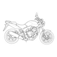
Honda CBF600S Service Manual (620 pages)
Brand:
Honda
| Category:
Motorcycle
| Size: 24.52 MB
Table of Contents
1. General Information
5
How to Use this Manual
3
Table of Contents
5
Service Rules
6
Model Identification
7
General Specifications
10
Lubrication System
10
Specifications
10
Specifications
11
Cooling System Specifications
12
Specifications
12
Clutch/Starter Clutch/Gearshift Linkage Specifications
13
Specifications
13
Crankshaft/Piston/Cylinder
14
Specifications
14
Front Wheel/Suspension/Steering Specifications
15
Specifications
16
Hydraulic Brake Specifications
16
Ignition System Specifications
16
Electric Starter Specifications
17
Lights/Meters/Switches
17
Specifications
17
Standard Torque Values
18
Engine & Frame Torque Values
18
Lubrication & Seal Points
25
Cable & Harness Routing
28
Emission Control Systems
52
Noise Emission Control System
54
2. Frame/Body Panels/Exhaust System
55
Body Panel Locations
56
Service Information
57
Troubleshooting
57
Seat
58
Seat Bracket
58
Rear Cowl
59
Side Cover
59
Front Fender
60
Rear Fender
61
Rear View Mirror (Cbf600S/Sa)
62
(Cbf600S/Sa)
63
Front Left/Right Cowl
63
Windscreen (Cbf600S/Sa)
63
Front Center Cowl
64
Meter Panel (Cbf600S/Sa)
64
Exhaust Pipe
65
Muffler
65
Main Stand (Cbf600Sa/Na)
67
3. Maintenance
69
Service Information
70
Maintenance Schedule
72
Fuel Line
73
Throttle Operation
74
Air Cleaner
75
Crankcase Breather
75
Spark Plug
76
Valve Clearance
77
Engine Oil/Oil Filter
82
Oil Level Inspection
82
Cooling System
85
Radiator Coolant
85
Secondary Air Supply System
86
Drive Chain
87
Drive Chain Slider
91
Brake Fluid
92
Front Brake
92
Brake Pad Wear
93
Brake System
94
Brake Lever Adjustment
94
Brake Pedal Height Adjustment
94
Brake Light Switch
95
Headlight Aim
95
Clutch System
96
Sidestand
96
Suspension
97
Nuts, Bolts, Fasteners
98
Wheels/Tires
98
Steering Head Bearings
99
4. Lubrication System
101
Lubrication System Diagram
102
Oil Pressure Inspection
105
Oil Strainer
106
Pressure Relief Valve
107
Oil Pump
108
5. Fuel System (Pgm-Fi)
115
Component Location
116
Service Information
117
Pgm-Fi System Location
120
Pgm-Fi System Diagram
121
Pgm-Fi Connector Locations
122
General Troubleshooting
125
System Description
125
Dtc Index
130
Dtc Troubleshooting
131
Mil Troubleshooting
150
Mil Circuit Troubleshooting
164
Fuel Line Inspection
165
Fuel Pressure Test
168
Fuel Pump
170
Fuel Cut-Off Relay
172
Fuel Tank
173
Air Cleaner Housing
175
Throttle Body
195
Injector
199
Engine Idle Speed
204
Iacv
204
Idle Speed Inspection
204
Map Sensor
206
Iat Sensor
207
Bank Angle Sensor
208
Ect Sensor
208
Engine Stop Relay
210
Ecm
211
Secondary Air Supply System
213
Intake Air Duct
215
O 2 Sensor
215
6. Cooling System
219
System Flow Pattern
220
Service Information
221
Troubleshooting
222
System Testing
223
Coolant Replacement
224
Thermostat
226
Radiator
229
Radiator Reserve Tank
235
Water Pump
235
7. Engine Removal/Installation
241
Component Location
242
Service Data
243
Crankcase Rear Cover Removal
244
Engine Installation
244
Engine Removal
244
Crankcase Rear Cover
257
Installation
257
8. Cylinder Head/Valves
259
Component Location
260
Service Information
261
Troubleshooting
263
Cylinder Compression Test
264
Cylinder Head Cover Removal
264
Cylinder Head Cover
265
Disassembly
265
Camshaft Removal
266
Cylinder Head Removal
270
Cylinder Head Disassembly
272
Cylinder Head Inspection
273
Valve Guide Replacement
276
Cylinder Head Assembly
280
Cylinder Head Installation
282
Camshaft Installation
284
Cylinder Head Cover Assembly
288
Cylinder Head Cover
289
Installation
289
9. Clutch/Starter Clutch/Gearshift Linkage
291
Component Location
292
Service Information
293
Troubleshooting
294
Right Crankcase Cover Removal
295
Clutch
296
Starter Clutch
307
Gearshift Linkage
312
Installation
315
Right Crankcase Cover
315
10. Alternator
319
Component Location
320
Service Information
321
Alternator Cover
322
Alternator Cover Removal
322
Installation
323
Alternator Cover Installation
325
11. Crankcase/Transmission
329
Component Location
330
Crankcase Separation
333
Shift Fork/Shift Drum
334
Transmission
334
Crankcase Assembly
344
Bearing Installation
358
Piston Removal
362
Cylinder Inspection
365
Torque Values
372
Front Wheel
383
Steering Stem
401
Bearing Replacement
403
Rear Wheel
417
Shock Absorber
424
15. Hydraulic Brake
437
Component Location
438
Service Information
440
Troubleshooting
442
Brake Fluid Replacement/Air Bleeding (Cbf600Sa/Na)
443
Brake Fluid Replacement/Air Bleeding (Cbf600S/N)
449
Brake Pad/Disc
451
Brake Disc Inspection
455
Front Master Cylinder
455
Rear Master Cylinder
460
Brake Pedal
461
Cbf600S/N
463
Cbf600Sa/Na
463
Cbf600S/N
466
Cbf600Sa/Na
466
16. Anti-Lock Brake System (Abs; Cbf600Sa/Na)
483
Abs System Location
484
Abs System Diagram
485
Service Information
486
Abs Connector Locations
487
Abs Problem Code Index
492
Abs Troubleshooting
493
Abs Indicator Circuit
503
Troubleshooting
503
Wheel Speed Sensor
506
Abs Modulator
509
Delay Valve
511
Pcv
511
17. Battery/Charging System
513
System Diagram
514
Charging System Inspection
519
Alternator Charging Coil
520
Battery
520
Ignition System Inspection
527
Ignition Coil
529
Ignition Timing
529
Starter Motor
536
Regulator/Rectifier
520
20. Lights/Meters/Switches
549
System Location
550
Service Information
551
Troubleshooting
553
Headlight
554
Position Light
557
Turn Signal
558
License Light
560
Tail/Brake Light
560
(Cbf600S/Sa)
561
Combination Meter
561
(Cbf600N/Na)
563
Combination Meter
563
Speedometer/Vs Sensor
571
Tachometer
573
Engine Coolant Temperature Indicator/Ect Sensor
575
Engine Oil Pressure Indicator
576
Eop Switch
576
Fuel Level Sensor
577
Ignition Switch
578
Handlebar Switches
580
Brake Light Switch
582
Clutch Switch
582
Neutral Switch
583
Sidestand Switch
584
Horn
585
Turn Signal Relay
586
(Cbf600S/Sa)
587
Fan Control Relay
587
Component Location
590
System Diagram
590
Service Information
591
Key Registration Procedures
592
Hiss Diagnostic Information
595
Immobilizer Indicator
600
(S/SA Model)
600
Immobilizer Indicator
601
(N/NA Model)
601
Ecm
602
Immobilizer Receiver
603
Wiring Diagrams
607
Poor Performance at High Speed
617
Wiring Diagram
620
Headlight Relay
587
Advertisement
Advertisement
Related Products
Honda CBF600N
Honda CBF600NA
Honda CBF600SA
Honda CBF600S 2006
Honda CBF600SA 2006
Honda CBF600N 2006
Honda CBF600NA 2006
Honda CBF190WH-G 2016
Honda CBF250NA 2023
Honda CBF150 2002
Honda Categories
Motorcycle
Automobile
Lawn Mower
Offroad Vehicle
Engine
More Honda Manuals
Login
Sign In
OR
Sign in with Facebook
Sign in with Google
Upload manual
Upload from disk
Upload from URL