Table of Contents
Advertisement
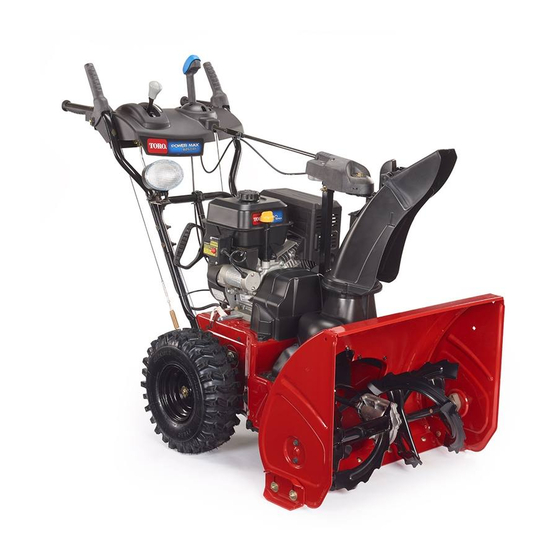
Power Max® 826 OXE Snowthrower
Model No. 37797—Serial No. 400000000 and Up
Introduction
This machine is intended to be used by residential
homeowners. It is designed primarily for removing
snow from paved surfaces, such as driveways and
sidewalks, and other surfaces for traffic on residential
or commercial properties. It is not designed for
removing materials other than snow.
Read this information carefully to learn how to operate
and maintain your product properly and to avoid
injury and product damage. You are responsible for
operating the product properly and safely.
You may contact Toro directly at www.Toro.com
for product safety and operation training materials,
accessory information, help finding a dealer, or to
register your product.
Whenever you need service, genuine Toro parts, or
additional information, contact an Authorized Service
Dealer or Toro Customer Service and have the model
and serial numbers of your product ready.
identifies the location of the model and serial numbers
on the machine. Write the numbers in the space
provided.
Important:
With your smartphone or tablet, scan
the QR code on the serial number decal to access
warranty, parts, and other product information.
1. Model and serial number location
© 2017—The Toro® Company
8111 Lyndale Avenue South
Bloomington, MN 55420
Figure 1
Figure 1
Register at www.Toro.com.
Model No.
Serial No.
This manual identifies potential hazards and has
safety messages identified by the safety-alert symbol
(Figure
2), which signals a hazard that may cause
serious injury or death if you do not follow the
recommended precautions.
This manual uses 2 words to highlight information.
Important calls attention to special mechanical
information and Note emphasizes general information
worthy of special attention.
Proposition 65 Warning
This product contains a chemical
or chemicals known to the State of
California to cause cancer, birth defects,
or reproductive harm.
The engine exhaust from this product
contains chemicals known to the State of
California to cause cancer, birth defects,
or other reproductive harm.
Important:
1500 m (5,000 ft) for a continuous
period, ensure that the High Altitude Kit has been
installed so that the engine meets CARB/EPA
emission regulations. The High Altitude Kit
increases engine performance while preventing
spark-plug fouling, hard starting, and increased
g219917
emissions. Once you have installed the kit, attach
the high-altitude label next to the serial decal on
the machine. Contact any Authorized Toro Service
Dealer to obtain the proper High Altitude Kit and
high-altitude label for your machine. To locate
a dealer convenient to you, access our website
at www.Toro.com or contact our Toro Customer
Original Instructions (EN)
Form No. 3415-763 Rev B
Operator's Manual
Figure 2
Safety-alert symbol
WARNING
CALIFORNIA
All Rights Reserved *3415-763* B
Printed in Mexico
g000502
Advertisement
Table of Contents

Related Manuals for Toro 37797


Summary of Contents for Toro 37797
-
Page 1: Introduction
This manual uses 2 words to highlight information. additional information, contact an Authorized Service Important calls attention to special mechanical Dealer or Toro Customer Service and have the model information and Note emphasizes general information and serial numbers of your product ready. -
Page 2: Table Of Contents
Care Department at the number(s) listed in your After Operation Safety ........15 Emission Control Warranty Statement. Remove Preventing Freeze-up after Use ......15 the kit from the engine and restore the engine to Maintenance ............16 its original factory configuration when running the Recommended Maintenance Schedule(s) ... -
Page 3: Figure
Safety • Do not operate the machine without all guards and other safety protective devices in place and working on the machine. General Safety • Keep clear of any discharge opening. Keep bystanders a safe distance away from the This machine complies with ANSI B71.3 specifications. machine. - Page 4 decal121-6817 121-6817 1. Cutting/dismemberment hazards of hand or foot, impeller and auger—keep bystanders a safe distance away from the machine. decal131-6487 131-6487 1. Engine—shut off 3. Fast decal121-6823 121-6823 2. Slow 1. Fast 3. Slow 2. Forward speeds 4. Reverse speeds decal121-1240 121-1240 Order Part No.
-
Page 5: Setup
Installing the Setup Traction-Control Linkage Installing the Upper Handle g219873 Installing the Chute g219875 g219874... -
Page 6: Installing The Chute-Control Rod
Installing the Chute-Control Installing the Snow-Cleanout Tool g219876 g219878 Connecting the Headlight Checking the Engine-Oil Wire Level Note: Your machine comes with oil in the engine crankcase. Before starting the engine, check the oil level and add oil if necessary. Refer to Checking the Engine-Oil Level (page 17). -
Page 7: Checking The Tire Pressure
Checking the Tire Pressure g001011 Figure 11 The machine should move rearward. If the machine does not move or moves forward, complete the following: Release the traction lever and shut off the engine. Disconnect the trunnion from the g219877 speed-selector lever. Turn the trunnion downward (clockwise) on the speed-control rod. -
Page 8: Product Overview
Product Overview g004217 Figure 14 1. Snow-cleanout tool (attached to the handle) Operation Before Operation Before Operation Safety • For electric-start models only: Use extension cords and receptacles as specified in the manual. Thoroughly inspect the electrical cord before plugging it into a power source. If the cord is g220002 Figure 12 damaged, do not use it. -
Page 9: Filling The Fuel Tank
During Operation DANGER Fuel is extremely flammable and explosive. A During Operation Safety fire or explosion from fuel can burn you and others. • Shut off the engine before unclogging the • To prevent a static charge from igniting the machine and always use a stick or the fuel, place the container and/or machine on snow-cleanout tool (if provided). - Page 10 g037221 Figure 18 Temperature Suggested Number of g016512 Primes Figure 16 -23°C (-10°F) and above Below -23°C (-10°F) Fully insert the ignition key (Figure 17). Move the choke to the C position (Figure HOKE 19). g016498 Figure 17 1. Ignition key Firmly push in the primer with your thumb as g016501 Figure 19...
-
Page 11: Shutting Off The Engine
5 seconds off), no more than 10 times. If the engine still does not start, take the machine to an Authorized Service Dealer for service. Disconnect the power cord from the power outlet first and then from the machine (electric-start models only). -
Page 12: Operating The Traction Drive
g001011 Figure 24 To stop the traction drive, release the traction lever. Operating the Speed Selector The speed selector has 6 forward and 2 reverse gears. To change speeds, release the traction lever g016499 Figure 23 and shift the speed-selector lever to the desired position (Figure 25). -
Page 13: Operating The Quick Stick
To stop the auger and impeller, release the right lever. Important: When you engage both the auger/impeller lever and the traction lever, the traction lever locks the auger/impeller lever down, freeing your right hand. To release both levers, simply release the left (traction) lever. -
Page 14: Clearing A Clogged Discharge Chute
Clearing a Clogged Operating Tips Discharge Chute DANGER When the machine is in operation, the impeller WARNING and auger rotate and can injure or amputate If the auger/impeller is running but there is no hands or feet. snow coming out of the discharge chute, the •... -
Page 15: After Operation
After Operation After Operation Safety • Never store the machine with fuel in the fuel tank inside a building where ignition sources are present, such as hot water heaters, space heaters, or clothes dryers. Allow the engine to cool before storing in any enclosure. -
Page 16: Maintenance
• Do not change the governor settings on the engine. • Purchase only genuine Toro replacement parts and accessories. Preparing for Maintenance Move the machine to a level surface. Shut off the engine and wait for all moving parts to stop. -
Page 17: Checking The Engine-Oil Level
Checking the Engine-Oil Checking and Adjusting the Level Skids and Scraper Service Interval: Before each use or daily—Check Service Interval: Yearly—Check the skids and the engine-oil level and add oil if the scraper and adjust them if necessary. necessary. Check the skids and the scraper to ensure that the auger does not contact the paved or gravel surface. -
Page 18: Checking And Adjusting The Traction Cable
Checking and Adjusting the Traction Cable Service Interval: After the first 2 hours—Inspect the traction cable and adjust it if necessary. Yearly—Inspect the traction cable and adjust or replace it if necessary. If the machine does not drive in the forward or reverse speeds or it drives when you release the traction lever, adjust the traction cable. -
Page 19: Checking The Auger-Gearbox-Oil Level
Loosen or tighten the turnbuckle to adjust the Remove the pipe plug from the gearbox. spring length to 7 cm (2-3/4 inches) as shown Check the oil level in the gearbox. The oil should Figure be 9.5 mm (3/8 inch) below the filler opening. If the oil level is low, add GL-5 or GL-6, SAE 80-90 EP gear oil lubricant to the gearbox until the oil level is 9.5 mm (3/8 inch) below the filler... -
Page 20: Lubricating The Hex Shaft
Wait until the engine is cool to replace the and block it so that it cannot fall. spark plug. Remove the back cover (Figure 40). Use a Toro spark plug or equivalent (Champion® RN9YC or NGK BPR6ES). Remove the boot (Figure 41). -
Page 21: Adjusting The Discharge-Chute Latch
Bulb g001029 Figure 43 Use a Toro light bulb or equivalent (GE 899 37W 1. 0.76 mm (0.030 inch) halogen bulb). Do not touch the bulb with your hands or allow dirt or moisture to come into contact with the bulb. - Page 22 g001036 Figure 49 g001037 Figure 45 Insert the wire connector straight into the back of the headlight until it is securely in place (Figure Turn the base of the bulb counterclockwise until 50). it stops (Figure 46). g001033 Figure 46 Remove the bulb straight out from the back of the headlight (Figure...
-
Page 23: Storage
Storage Storing the Machine On the last refueling of the year, add fuel stabilizer to fresh fuel as directed by the fuel stabilizer manufacturer. Important: Do not store fuel longer than that suggested by the fuel stabilizer manufacturer. Run the engine for 10 minutes to distribute the conditioned fuel through the fuel system. -
Page 24: Troubleshooting
Troubleshooting Problem Possible Cause Corrective Action The electric starter does not turn 1. The power cord is disconnected at the 1. Connect the power cord to the outlet (electric-start models only). outlet or the machine. and/or the machine. 2. The power cord is worn, corroded, or 2. - Page 25 5. Unclog the discharge chute. 6. The auger/impeller drive belt is loose 6. Install and/or adjust the auger/impeller or is off the pulley. drive belt; refer to www.Toro.com for servicing information or take the machine to an Authorized Service Dealer.
- Page 26 Notes:...
- Page 27 Notes:...