
Related Manuals for Miller Electric 350 VS


Summary of Contents for Miller Electric 350 VS
- Page 1 OM-2251 217 661J 2007−11 Processes Multiprocess Welding Description Arc Welding Power Source XMT 350 VS Auto-Line File: MULTIPROCESS Visit our website at www.MillerWelds.com...
- Page 2 ISO 9001:2000 Quality System Standard. particular model are also provided. Miller Electric manufactures a full line of welders and welding related equipment. For information on other quality Miller products, contact your local Miller distributor to receive the latest full line catalog or individual specification sheets.
-
Page 3: Table Of Contents
TABLE OF CONTENTS SECTION 1 − SAFETY PRECAUTIONS - READ BEFORE USING 1-1. Symbol Usage ............... . 1-2. -
Page 5: Section 1 − Safety Precautions - Read Before Using
DC constant voltage (wire) welder, 2) a DC manual (stick) welder, or 3) an AC welder with reduced open-circuit volt- age. In most situations, use of a DC, constant voltage wire welder is recommended. And, do not work alone! D Disconnect input power or stop engine before installing or servicing this equipment. - Page 6 OM-2251 Page 2 D Do not use welder to thaw frozen pipes. D Remove stick electrode from holder or cut off welding wire at contact tip when not in use.
-
Page 7: Additional Symbols For Installation, Operation, And Maintenance
1-3. Additional Symbols For Installation, Operation, And Maintenance FIRE OR EXPLOSION hazard. D Do not install or place unit on, over, or near combustible surfaces. D Do not install unit near flammables. D Do not overload building wiring − be sure power supply system is properly sized, rated, and protected to handle this unit. -
Page 8: California Proposition 65 Warnings
1-4. California Proposition 65 Warnings Welding or cutting equipment produces fumes or gases which contain chemicals known to the State of California to cause birth defects and, in some cases, cancer. (California Health & Safety Code Section 25249.5 et seq.) Battery posts, terminals and related accessories contain lead and lead compounds, chemicals known to the State of California to cause cancer and birth defects or other... -
Page 9: Section 2 − Consignes De Sécurité − Lire Avant Utilisation
SECTION 2 − CONSIGNES DE SÉCURITÉ − LIRE AVANT UTILISATION Se protéger et protéger les autres contre le risque de blessure — lire et respecter ces consignes. 2-1. Symboles utilisés DANGER! − Indique une situation dangereuse qui si on l’évite pas peut donner la mort ou des blessures graves. Les dangers possibles sont montrés par les symboles joints ou sont expliqués dans le texte. - Page 10 Il reste une TENSION DC NON NÉGLIGEABLE dans les sources de soudage onduleur quand on a coupé l’alimentation. D Arrêter les convertisseurs, débrancher le courant électrique et décharger les condensateurs d’alimentation selon les instructions indiquées dans la partie Entretien avant de toucher les pièces. DES PIÈCES CHAUDES peuvent provoquer des brûlures graves.
-
Page 11: Dangers Supplémentaires En Relation Avec L'installation, Le Fonctionnement Et La Maintenance
ACCUMULATIONS risquent de provoquer des blessures ou même la mort. D Fermer l’alimentation du gaz protecteur en cas de non-utilisation. D Veiller toujours à bien aérer les espaces confi- nés ou se servir d’un respirateur d’adduction d’air homologué. LES CHAMPS MAGNETIQUES peuv- ent affecter des implants médicaux. -
Page 12: Proposition Californienne 65 Avertissements
LES FILS DE SOUDAGE peuvent provoquer des blessures. D Ne pas appuyer sur la gâchette avant d’en avoir reçu l’instruction. D Ne pas diriger le pistolet vers soi, d’autres per- sonnes ou toute pièce mécanique en enga- geant le fil de soudage. DES ORGANES MOBILES peuvent provoquer des blessures. -
Page 13: Principales Normes De Sécurité
2-5. Principales normes de sécurité Safety in Welding, Cutting, and Allied Processes, ANSI Standard Z49.1, de Global Engineering Documents (téléphone : 1-877-413-5184, site Internet : www.global.ihs.com). Recommended Safe Practices for the Preparation for Welding and Cut- ting of Containers and Piping, American Welding Society Standard AWS F4.1 de Global Engineering Documents (téléphone : 1-877-413-5184, site Internet : www.global.ihs.com). - Page 14 OM-2251 Page 10...
-
Page 15: Section 3 − Introduction
SECTION 3 − INTRODUCTION 3-1. Specifications Input Input Voltage Voltage Power Range in CV Mode Rated Output 3-Phase 350 A at 34 10−38 V VDC, 60% Duty Cycle 1-Phase 300 A at 32 VDC, 60% Duty Cycle* *See Section 3-3 for Duty Cycle Rating. 3-2. -
Page 16: Duty Cycle And Overheating
3-3. Duty Cycle And Overheating 6 Minutes Welding Overheating Notes OM-2251 Page 12 60% Duty Cycle 4 Minutes Resting Reduce Duty Cycle Minutes Duty Cycle is percentage of 10 min- utes that unit can weld at rated load without overheating. If unit overheats, output stops, a Help message is displayed and cooling fan runs. -
Page 17: Section 4 − Installation
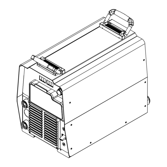
SECTION 4 − INSTALLATION 4-1. Dimensions And Weight Hole Layout Dimensions 11-3/4 in (298 mm) 1-11/16 in (42 mm) 15-3/4 in (400 mm) 19-3/32 in (485 mm) 8-11/16 in (221 mm) 1-17/32 in (39 mm) 1/4-20 UNC -2B thread Weight 80 lb (36.3 kg) 4-2. -
Page 18: Connecting 1-Phase Input Power
4-3. Connecting 1-Phase Input Power Tools Needed: OM-2251 Page 14 =GND/PE Earth Ground Insulate and isolate red conductor as shown. Connect green grounding conductor to disconnect device grounding terminal first. Connect input conductors L1 and L2 to disconnect device line terminals. 10 Overcurrent Protection Select type and size of overcurrent protection using Section 4-5 (fused... -
Page 19: Connecting 3-Phase Input Power
4-4. Connecting 3-Phase Input Power Tools Needed: = GND/PE Earth Ground Installation must meet all National and Local Codes − have only quali- fied persons make this installation. Disconnect and lockout/tagout in- put power before connecting input conductors from unit. Always connect green or green/ yellow conductor... -
Page 20: Electrical Service Guide
4-5. Electrical Service Guide NOTICE − INCORRECT INPUT POWER can damage this welding power source. Phase to ground voltage shall not exceed +10% of rated input voltage. NOTICE − Actual input voltage should not be 10% less than minimum and/or 10% more than maximum input voltages listed in table. If actual input voltage is outside this range, output may not be be available. -
Page 21: Weld Output Terminals And Selecting Cable Sizes
4-6. Weld Output Terminals And Selecting Cable Sizes ARC WELDING can cause Electromagnetic Interference. To reduce possible interference, keep weld cables as short as possible, close together, and down low, such as on the floor. Locate welding operation 100 meters from any sensitive electronic equipment. Be sure this welding machine is installed and grounded according to this manual. -
Page 22: Optional Gas Valve Operation And Shielding Gas Connection
‘ 4-7. Optional Gas Valve Operation And Shielding Gas Connection GAS IN GAS OUT OM-2251 Page 18 Obtain gas cylinder and chain to running gear, wall, or other station- ary support so cylinder cannot fall and break off valve. Cylinder Regulator/Flowmeter Install so face is vertical. -
Page 23: Section 5 − Operation
SECTION 5 − OPERATION 5-1. Front Panel Controls Power Switch The fan motor is thermostatically controlled and only runs when cooling is needed. Voltmeter Ammeter V/A (Voltage/Amperage) Adjustment Control Mode Switch Mode switch setting determines the process. ARC CONTROL For Air Carbon Arc (CAC-A) cutting and goug- ing, place switch in Stick position. -
Page 24: Meter Functions
5-2. Meter Functions The meters display the actual weld output values for approximately three seconds after the arc is broken. Mode Scratch Start TIG Actual Volts (OCV) Lift-Arc TIG Actual Volts Stick Actual Volts (OCV) V-Sense Feeder Flashes OCV And Preset 5-3. -
Page 25: Lift-Arc Tig Procedure
5-4. Lift-Arc TIG Procedure “Touch” Do NOT Strike Like A Match! 5-5. Stick Start Procedure 1 − 2 Seconds With Process Switch in the Lift-Arc TIG position, start an arc as follows: TIG Electrode Workpiece Touch tungsten electrode to work- piece at weld start point, hold electrode to workpiece for 1-2 seconds, and slowly lift electrode. -
Page 26: Section 6 − Maintenance & Troubleshooting
SECTION 6 − MAINTENANCE & TROUBLESHOOTING 6-1. Routine Maintenance Replace Damaged Or Unreadable Labels 6-2. Blowing Out Inside Of Unit OM-2251 Page 22 Disconnect power before maintaining. 3 Months Repair Or Replace Cracked Cables 6 Months Blow Out Inside Maintain more often during severe conditions. -
Page 27: Voltmeter/Ammeter Help Displays
6-3. Voltmeter/Ammeter Help Displays HE.L P−1 HE.L P−2 HE.L P−3 All directions are in reference to the front of the unit. All circuitry referred to is lo- cated inside the unit. Help 1 Display Indicates a malfunction in the primary power circuit. -
Page 28: Section 7 − Electrical Diagram
SECTION 7 − ELECTRICAL DIAGRAM Figure 7-1. Circuit Diagram OM-2251 Page 24... - Page 29 219 863-C OM-2251 Page 25...
-
Page 30: Section 8 − Parts List
SECTION 8 − PARTS LIST Ref. 803 729-H Figure 8-1. Parts Assembly OM-2251 Page 26... - Page 31 Item Dia. Part Mkgs....216 034 ..... 175 256 .
- Page 32 Item Dia. Part Mkgs....225 442 ....126 026 ..... 223 343 .
- Page 33 Notes...
- Page 34 Notes Start Your Professional Over 80,000 trained 400 Trade Square East, Troy, Ohio 45373 Welding Career Now! since 1930! 1-800-332-9448 www.welding.org...
- Page 35 Warranty Questions? LIMITED WARRANTY − Subject to the terms and conditions Call below, Miller Electric Mfg. Co., Appleton, Wisconsin, warrants to 1-800-4-A-MILLER its original retail purchaser that new Miller equipment sold after the effective date of this limited warranty is free of defects in for your local material and workmanship at the time it is shipped by Miller.
-
Page 36: Owner's Record
File a claim for loss or damage during shipment. For assistance in filing or settling claims, contact your distributor and/or equipment manufacturer’s Transportation Department. 2007 Miller Electric Mfg. Co. 2007−01 Miller Electric Mfg. Co. An Illinois Tool Works Company 1635 West Spencer Street Appleton, WI 54914 USA International Headquarters−USA...
Need help?
Do you have a question about the 350 VS and is the answer not in the manual?
Questions and answers