Miller Electric Millermatic 350P Aluminum Owner's Manual
Hide thumbs
Also See for Millermatic 350P Aluminum:
- Owner's manual (60 pages) ,
- Owner's manual (60 pages)
Table of Contents
Advertisement
Quick Links
Advertisement
Table of Contents
Troubleshooting

Related Manuals for Miller Electric Millermatic 350P Aluminum


Summary of Contents for Miller Electric Millermatic 350P Aluminum
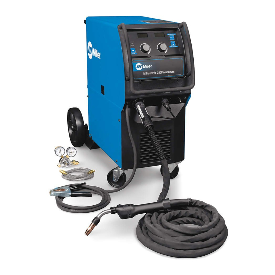
- Page 1 OM-254915E 2020−09 Processes MIG (GMAW) Welding Pulsed MIG (GMAW-P) Description Arc Welding Power Source and Wire Feeder Millermatic 350P Aluminum For product information, File: MIG (GMAW) Owner’s Manual translations, and more, visit www.MillerWelds.com...
- Page 2 U.S.A. to be registered to the ISO 9001 Quality System Standard. Miller Electric manufactures a full line of welders and welding-related equipment. For information on other quality Miller products, contact your local Miller distributor to receive the latest full line catalog or individual specification sheets.
-
Page 3: Table Of Contents
..............4-7. Millermatic 350P Aluminum Differences vs Standard Millermatic 350/350P . - Page 4 TABLE OF CONTENTS 6-3-4-2. Preflow ..............6-3-4-3.
-
Page 5: Section 1 − Safety Precautions - Read Before Using
SECTION 1 − SAFETY PRECAUTIONS - READ BEFORE USING som 2020−02 Protect yourself and others from injury — read, follow, and save these important safety precautions and operating instructions. 1-1. Symbol Usage DANGER! − Indicates a hazardous situation which, if Indicates special instructions. - Page 6 D Do not cut or weld on tire rims or wheels. Tires can explode if heat- FUMES AND GASES can be hazardous. ed. Repaired rims and wheels can fail. See OSHA 29 CFR 1910.177 listed in Safety Standards. D Do not weld on containers that have held combustibles, or on Welding produces fumes and gases.
-
Page 7: Additional Hazards For Installation, Operation, And Maintenance
D Never weld on a pressurized cylinder − explosion will result. CYLINDERS can explode if damaged. D Use only correct compressed gas cylinders, regulators, hoses, and fittings designed for the specific application; maintain them Compressed gas cylinders contain gas under high and associated parts in good condition. -
Page 8: California Proposition 65 Warnings
H.F. RADIATION can cause interference. ARC WELDING can cause interference. D High-frequency (H.F.) can interfere with radio D Electromagnetic energy can interfere with navigation, safety services, computers, and sensitive electronic equipment such as communications equipment. computers and computer-driven equipment such as robots. D Have only qualified persons familiar with electronic equipment D Be sure all equipment in the welding area is electromagnetically perform this installation. -
Page 9: Section 2 − Consignes De Sécurité − Lire Avant Utilisation
SECTION 2 − CONSIGNES DE SÉCURITÉ − LIRE AVANT UTILISATION som_2020−02_fre Pour écarter les risques de blessure pour vous−même et pour autrui — lire, appliquer et ranger en lieu sûr ces consignes relatives aux précautions de sécurité et au mode opératoire. 2-1. - Page 10 D Déplacer toutes les substances inflammables à une distance de LES PIÈCES CHAUDES peuvent 10,7 m de l’arc de soudage. En cas d’impossibilité les recouvrir provoquer des brûlures. soigneusement avec des protections homologués. D Ne pas toucher à mains nues les parties chaudes. D Ne pas souder dans un endroit là...
-
Page 11: Symboles De Dangers Supplémentaires En Relation Avec L'installation, Le Fonctionnement Et La Maintenance
D Protéger les bouteilles de gaz comprimé d’une chaleur excessive, Les CHAMPS ÉLECTROMAGNÉTIQUES (CEM) des chocs mécaniques, des dommages physiques, du laitier, des peuvent affecter les implants médicaux. flammes ouvertes, des étincelles et des arcs. D Placer les bouteilles debout en les fixant dans un support station- D Les porteurs de stimulateurs cardiaques et naire ou dans un porte-bouteilles pour les empêcher de tomber ou autres implants médicaux doivent rester à... -
Page 12: Proposition Californienne 65 Avertissements
D Effectuer régulièrement le contrôle et l’entretien de l’installation. LIRE LES INSTRUCTIONS. D Maintenir soigneusement fermés les portes et les panneaux des sources de haute fréquence, maintenir les éclateurs à une distan- D Lire et appliquer les instructions sur les ce correcte et utiliser une terre et un blindage pour réduire les étiquettes et le Mode d’emploi avant l’instal- interférences éventuelles. -
Page 13: Section 3 − Definitions
SECTION 3 − DEFINITIONS 3-1. Additional Safety Symbols And Definitions Warning! Watch Out! There are possible hazards as shown by the symbols. Safe1 2012−05 Drive rolls can injure fingers. Welding wire and drive parts are at welding voltage during operation − keep hands and metal objects away. -
Page 14: Miscellaneous Symbols And Definitions
3-2. Miscellaneous Symbols And Definitions Rated No Load Amperage Negative Voltage (OCV) Direct Current Voltage Input Primary Voltage (DC) Alternating Arc Control Press Current (AC) Constant Voltage Voltage Duty Cycle Purge By Gas Output Hertz Protective Earth Cold Jog (Inch) (Ground) Gun Control Toward Workpiece... -
Page 15: Section 4 − Specifications
4-3. Information About Default Weld Parameters And Settings NOTICE − Each welding application is unique. Although certain Miller Electric products are designed to determine and default to certain typical welding parameters and settings based upon specific and relatively limited application variables input by the end user, such default settings are for reference purposes only;... -
Page 16: Duty Cycle And Overheating
A complete Parts List is available at www.MillerWelds.com 4-5. Duty Cycle And Overheating Duty Cycle is percentage of 10 minutes that unit can weld at rated load without overheating. If unit overheats, thermistors open, output stops, and cooling fan runs. Wait fifteen minutes for unit to cool. -
Page 17: Millermatic 350P Aluminum Differences Vs Standard Millermatic 350/350P
SUP is gone − The new torque motor eliminates the need for SUP value in the Millermatic 350P Aluminum. Jog/Purge Button − For increased ease of use the Millermatic 350P Aluminum has a Jog/Purge button. With the press of a button the user can Jog wire or Purge gas. -
Page 18: Section 5 − Installation
A complete Parts List is available at www.MillerWelds.com SECTION 5 − INSTALLATION 5-1. Selecting A Location Do not move or operate unit Movement where it could tip. Special installation may be Location And Airflow required where gasoline or volatile liquids are present − see NEC Article 511 or CEC Section 20. -
Page 19: Weld Output Terminals And Selecting Cable Sizes
A complete Parts List is available at www.MillerWelds.com 5-2. Weld Output Terminals And Selecting Cable Sizes NOTICE − The Total Cable Length in Weld Circuit (see table below) is the combined length of both weld cables. For example, if the power source is 100 ft (30 m) from the workpiece, the total cable length in the weld circuit is 200 ft (2 cables x 100 ft). -
Page 20: Connecting To Weld Output Terminals
A complete Parts List is available at www.MillerWelds.com 5-3. Connecting To Weld Output Terminals Do not place anything between weld cable terminal and copper bar. Tools Needed: 3/4 in. (19 mm) 803 778-A Correct Installation Incorrect Installation Weld Output Terminal output terminal and secure with nut so that Turn off power before connecting to weld cable terminal is tight against copper... -
Page 21: Installing Welding Gun/Cable Holder
A complete Parts List is available at www.MillerWelds.com 5-5. Installing Welding Gun/Cable Holder Welding Gun/Cable Holder Wrapper Screw Locations Remove screws from side panel. Place holder against side panel and align screw holes. Secure holder to side panel with the previously removed screws. -
Page 22: Connecting Spoolmatic) 15A Or 30A Gun
A complete Parts List is available at www.MillerWelds.com 5-7. Connecting Spoolmatic) 15A Or 30A Gun Gun Trigger Plug Insert plug into receptacle, and tighten threaded collar. Weld Cable Shielding Gas Hose Route weld cable and gas hose through opening in front panel. Positive Weld Output Terminal Connect weld cable to weld output terminal. -
Page 23: Connecting Xr-A Gun, Xr-A Python, Or Xr-A Aluma-Pro, Or Xr-A Aluma-Pro Lite
A complete Parts List is available at www.MillerWelds.com 5-8. Connecting XR-A Gun, XR-A Python, Or XR-A Aluma-Pro, Or XR-A Aluma-Pro Lite Gun End Gun Liner Wire Outlet Guide Trim excess liner from end of gun so no more than 3/32 in. (2.4 mm) of liner extends past wire outlet guide. -
Page 24: Installing Gas Supply
A complete Parts List is available at www.MillerWelds.com 5-9. Installing Gas Supply Obtain gas cylinder and chain to running gear, wall, or other stationary support so cylinder cannot fall and break off valve. Cylinder Valve Remove cap, stand to side of valve, and open valve slightly. -
Page 25: Installing Wire Spool
A complete Parts List is available at www.MillerWelds.com 5-10. Installing Wire Spool Wire Spool Hub Pin Compression Spring Optional - For 8 Inch Spool (Part No. 057745). Retaining Ring Slide spool onto hub so wire feeds off top. Turn spool until hub pin fits hole in back of spool (notch on hub aligns with hub pin for guidance). -
Page 26: Electrical Service Guide
A complete Parts List is available at www.MillerWelds.com 5-11. Electrical Service Guide Elec Serv 2014−01 NOTICE − INCORRECT INPUT POWER can damage this welding power source. This welding power source requires a CONTINUOUS supply of input power at rated frequency(+10%) and voltage (+10%). Phase to ground voltage shall not exceed +10% of rated input voltage. Do not use a genera- tor with automatic idle device (that idles engine when no load is sensed) to supply input power to this welding power source. -
Page 27: Selecting Input Voltage
A complete Parts List is available at www.MillerWelds.com 5-12. Selecting Input Voltage Turn Off welding power source, disconnect input Be sure to reinstall all four screws power, and check voltage on securing relinking board in place. input capacitors according Section before proceeding. -
Page 28: Connecting 3-Phase Input Power
A complete Parts List is available at www.MillerWelds.com 5-13. Connecting 3-Phase Input Power = GND/PE Earth Ground Rear Panel Tools Needed: input2 2012−05 − Ref. 803 766-C / Ref. 804653-B / 803 766-A OM-254915 Page 24... - Page 29 A complete Parts List is available at www.MillerWelds.com 5-13. Connecting 3-Phase Input Power (Continued) For Three-Phase Operation conductor to disconnect device grounding Installation must meet all National and terminal first. Local Codes - have only qualified Input Power Cord Strain Relief persons make this installation.
-
Page 30: Connecting 1-Phase Input Power
A complete Parts List is available at www.MillerWelds.com 5-14. Connecting 1-Phase Input Power =GND/PE Earth Ground Rear Panel Tools Needed: input1 2012−05 − Ref. 803 766-C / Ref. 803 543-E / 803 766-A OM-254915 Page 26... - Page 31 A complete Parts List is available at www.MillerWelds.com 5-14. Connecting 1-Phase Input Power (Continued) Input Power Cord Strain Relief 10 Disconnect Device Line Terminals Installation must meet all National and Local Codes - have only qualified Black And White Input Conductor (L1 Connect green or green/yellow grounding persons make this installation.
-
Page 32: Changing Drive Rolls
A complete Parts List is available at www.MillerWelds.com 5-15. Changing Drive Rolls Retract wire onto spool. Pressure Roll Assembly Drive Motor Shaft Drive Roll Screw Drive Roll Idler Shoulder Washer (2) Remove drive roll, idler, and shoulder washers if changing wire size. -
Page 33: Threading Welding Wire
A complete Parts List is available at www.MillerWelds.com 5-16. Threading Welding Wire Wire Spool Welding Wire Inlet Wire Guide Drive Roll Wire Conduit Pressure Adjustment Knob Gun Conduit Cable Jog/Purge Switch Lay gun cable out straight. Tools Needed: Hold wire tightly to keep it from unraveling. -
Page 34: Threading Welding Wire Through Xr Guns
A complete Parts List is available at www.MillerWelds.com 5-17. Threading Welding Wire Through XR Guns Welding wire is electrically live when gun trigger is used to jog wire. For XR-A Edge Gun: Refer to Section 5-16 for instructions on feeding wire through welding pow- er source. -
Page 35: Section 6 − Operation
A complete Parts List is available at www.MillerWelds.com SECTION 6 − OPERATION 6-1. Operational Terms The following is a list of terms and their definitions as they apply to this interface unit: General Terms: Arc Length Distance from end of wire electrode to workpiece. Crater Provides voltage/arc length, wire feed speed and time values for modified arc end. -
Page 36: Controls
A complete Parts List is available at www.MillerWelds.com 6-2. Controls 1011 13 1415 Wire Compartment Ref. 242 929-C / Ref. 255 204-B PULSE Indicator Light SETUP Button 17 Right SETUP Indicator Light MIG Indicator Light 10 VOLTS Indicator Light 18 Left Knob SYNERGIC Indicator Light 11 ARC LENGTH Indicator Light 19 Right Knob... -
Page 37: Setup Button
A complete Parts List is available at www.MillerWelds.com 6-3. Setup Button 6-3-1. Gun Lit Indicators This menu allows the user to select a gun to configure such as Python, Aluma-Pro, or XR-A. Ref. 242 929-C 6-3-2. Process Lit Indicators This menu allows the user to select a welding process. -
Page 38: Wire
A complete Parts List is available at www.MillerWelds.com 6-3-3. Wire Lit Indicators This menu allows the user to select the wire alloy and diameter. Ref. 242 929-C Notes OM-254915 Page 34... -
Page 39: Timers
A complete Parts List is available at www.MillerWelds.com 6-3-4. Timers Lit Indicators Rotating the left adjustment knob will cycle through the timer options. Ref. 242 929-C 6-3-4-1. Run-in In this menu the user can adjust the wire feed speed prior to the welding arc being established. This setting is a percentage of the wire feed speed the unit is set to for welding. -
Page 40: Hot Start (Pulse Mode Only)
A complete Parts List is available at www.MillerWelds.com 6-3-5. Hot Start (Pulse Mode Only) Lit Indicators To enable this feature the user must first access the system menu and turn the “ALST” feature to “ON”. For more information on the system menu see Section 6-14. -
Page 41: Crater Fill
A complete Parts List is available at www.MillerWelds.com 6-3-6. Crater Fill Lit Indicators To enable this feature the user must first access the system menu and turn the “CRTR” feature to “ON”. For more information on the system menu see section 6-14. For more information about the crater func- tion see section 6-18. -
Page 42: Mig Mode
A complete Parts List is available at www.MillerWelds.com 6-4. MIG Mode Lit Indicators Ref. 242 929-C When the MIG light (2) is illuminated, the Depress SETUP (6) button again to ARC CONTROL unit is in MIG Welding mode. illuminate the WIRE (4) light. Adjust left MIG welding mode: Depress ARC knob (8) to select wire type, adjust right CONTROL (7) button to enter Arc control... -
Page 43: Synergic Mig Mode
A complete Parts List is available at www.MillerWelds.com 6-5. Synergic MIG Mode Lit Indicators Synergic MIG Mode is a convenient and helpful extension to regular MIG mode. In Synergic MIG mode, the voltage is calculated as a function of the wire feed speed. Therefore, as the user adjusts the wire feed speed up and down the voltage tracks up and down to keep... -
Page 44: Pulse Mig Mode
A complete Parts List is available at www.MillerWelds.com 6-6. Pulse MIG Mode Lit Indicators Ref. 242 929-C OPERATION ARC CONTROL When PULSE and MIG are illuminated, the unit is in Pulse MIG Welding mode. When in Pulse MIG welding mode, depress Arc length can be adjusted from 0-99. -
Page 45: Jog Mode
A complete Parts List is available at www.MillerWelds.com 6-7. Jog Mode Lit Indicators JOG − Jog Mode The Millermatic 350P Aluminum provides the ability to jog the wire by means of the gun trigger or the Jog/ Purge switch. If an arc is not estab-... -
Page 46: Purge Mode
A complete Parts List is available at www.MillerWelds.com 6-8. Purge Mode PURG GAS − Purge Mode The Millermatic 350P Aluminum is equipped with a Jog/Purge switch located in the wire compartment. Pressing the Purge button allows shielding gas to flow. This feature... -
Page 47: Trigger Hold Feature
A complete Parts List is available at www.MillerWelds.com 6-10. Trigger Hold Feature Lit Indicator The trigger hold feature is enabled and disabled by pressing the Trigger Hold Button. The Trigger Hold Indicator Light indicates the feature is on or off. An additional trigger hold setting appears in the TIMERS menu;... -
Page 48: Trigger Pulls That Will Not Actuate Trigger Hold
A complete Parts List is available at www.MillerWelds.com 6-12. Trigger Pulls That Will Not Actuate Trigger Hold OM-254915 Page 44... -
Page 49: Arc Control
A complete Parts List is available at www.MillerWelds.com 6-13. Arc Control Lit Indicator The arc control menu allows the user to adjust the inductance or sharp arc (depending on welding process). While MIG welding, changing the inductance will change the fluidity of the puddle. While Pulse welding, changing the SharpArc will vary the width of the welding cone. -
Page 50: System Menu
A complete Parts List is available at www.MillerWelds.com 6-14. System Menu Lit Indicators To access the system menu press both the setup button and the Arc Control button at the same time. Once on the system menu the left adjustment knob scrolls through the options. -
Page 51: Gun Calibration
A complete Parts List is available at www.MillerWelds.com 6-15. Gun Calibration Lit Indicators G.CAL NO − Gun Calibration Gun calibration is used to improve wire feed speed accuracy. A gun calibration is recommended during installation or when changing guns. To perform a calibration, connect the gun to the machine and thread G.CAL the wire all the way through the... -
Page 52: Trigger Schedule Select
A complete Parts List is available at www.MillerWelds.com 6-16. Trigger Schedule Select Lit Indicator The Trigger Schedule Select is an advanced feature that allows chan- ging between two sets of weld para- meters. To activate the Trigger Se- lect feature, simultaneously de- press both the blue set-up and arc control buttons. -
Page 53: Hot Start (Pulse Mode Only)
SPWR − Hot Start knob one last time brings the user to the fi- setup button should bring the user to a The Millermatic 350P Aluminum is nal menu labeled “RMPT”. This repres- menu indicated by “SPWR” on the left dis- equipped with a hot start feature. -
Page 54: Crater Fill
If the arc gun). The right adjustment knob will en- time is less than the TDLY time the follow- The Millermatic 350P Aluminum is able or disable the crater sequence for the ing trigger pull will be normal weld output, equipped with a crater fill feature. -
Page 55: System Reset
A complete Parts List is available at www.MillerWelds.com Table 4-1. Recommended Crater Fill Parameters (Wire Feed Speed/Voltage Or Arc Length/Time) MIG Setting Example Pulse Setting Example Wire Speed / 90 Volts / 13.5 Time / 1.0 Wire Speed / 90 Arc Length / 30 Time / 1.0 Sugges-... -
Page 56: Section 7 − Maintenance &Troubleshooting
A complete Parts List is available at www.MillerWelds.com SECTION 7 − MAINTENANCE &TROUBLESHOOTING 7-1. Routine Maintenance Disconnect power before maintaining. Maintain more often during severe conditions. n = Check Z = Change ~ = Clean l = Replace Reference * To be done by Factory Authorized Service Agent Every l Damaged Or Unreadable l Repair Or Replace... -
Page 57: Feeder Drive Assembly Maintenance
A complete Parts List is available at www.MillerWelds.com 7-4. Feeder Drive Assembly Maintenance Retract wire onto spool. Pressure Roll Assembly Drive Motor Shaft Drive Roll Screw Use wire brush to clean drive roll. Drive Roll Idler Shoulder Washers Use wire brush to clean idler. Outlet Guide Wire Inlet Guide Pull guide toward rear of feeder to... -
Page 58: Replacing Hub Assembly
A complete Parts List is available at www.MillerWelds.com 7-5. Replacing Hub Assembly Remove gun top cover and release pressure arm. Retract wire onto spool and remove spool. Take hub apart as shown. Plastic Brake Washer Fiber Washer Brake Washer Keyed Washer Spring Flat Washer Cap Screw... -
Page 59: Measuring And Discharging Input Capacitor Voltage
A complete Parts List is available at www.MillerWelds.com 7-6. Measuring And Discharging Input Capacitor Voltage Turn Off welding power source, and disconnect in- put power. Significant DC voltage can remain on capacitors after unit is Off. Always check ca- pacitors as shown to be sure they have discharged before working on unit. -
Page 60: Help And Information Displays
A complete Parts List is available at www.MillerWelds.com 7-7. Help And Information Displays HELP G.CAL ERR.1 HELP G.CAL ERR.2 HELP Displays a jog wire feed speed. HELP HELP HELP HELP HELP OM-254915 Page 56... - Page 61 A complete Parts List is available at www.MillerWelds.com Help 3 Help 8 All directions are in reference to the Indicates gun trigger was pulled and held front of the unit. All circuitry referred to during power up. Release gun trigger and Indicates open circuit voltage is out of range.
-
Page 62: Troubleshooting
A complete Parts List is available at www.MillerWelds.com 7-8. Troubleshooting Trouble Remedy No weld output; wire does not feed. Be sure line disconnect switch is On (see Section 5-13 or 5-14). Replace building line fuse or reset circuit breaker if open (see Section 5-13 or 5-14). Secure gun trigger connections (see Section 5-6). - Page 63 Notes OM-254915 Page 59...
-
Page 64: Section 8 − Electrical Diagram
SECTION 8 − ELECTRICAL DIAGRAM Figure 8-1. Circuit Diagram For Welding Power Source OM-254915 Page 60... - Page 65 255730-J OM-254915 Page 61...
-
Page 66: Section 9 − Parts List
SECTION 9 − PARTS LIST 9-1. Drive Roll Kits And Wire Guides Wire Diameter Kit No. Inlet Wire Guide Fraction Decimal Metric .030/.035 in. .030/.035 in. 0.8/.09 196 301 058 549 .040 in. .040 in. 1.0 mm 194 118 058 549 3/64 in. - Page 67 LIMITED WARRANTY − Subject to the terms and conditions Supplied Air Respirator (SAR) Boxes and Panels below, Miller Electric Mfg. LLC, Appleton, Wisconsin, warrants to Warranty Questions? TIG Torches (No Labor) authorized distributors that new Miller equipment sold after the...
- Page 68 Contact the Delivering Carrier to: File a claim for loss or damage during shipment. For assistance in filing or settling claims, contact your distributor and/or equipment manufacturer’s Transportation Department. © ORIGINAL INSTRUCTIONS − PRINTED IN USA 2020 Miller Electric Mfg. LLC 2020−01...
Need help?
Do you have a question about the Millermatic 350P Aluminum and is the answer not in the manual?
Questions and answers