
Related Manuals for Miller Electric Spoolmate 3035


Summary of Contents for Miller Electric Spoolmate 3035
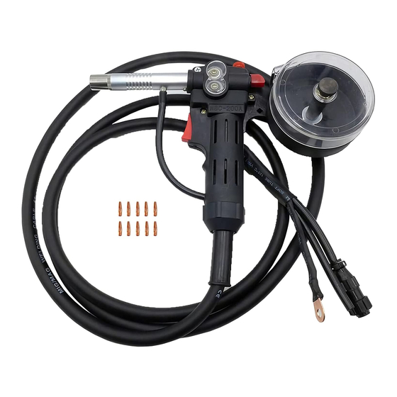
- Page 1 OM-1216 205 917D 2006−09 Processes MIG (GMAW) Welding Description Wire Feeder Spool Gun Spoolmate 3035 And 3545 Spoolmate 3545 Spoolmate 3035 File: Wire Feeder Visit our website at www.MillerWelds.com...
- Page 2 ISO 9001:2000 Quality System Standard. particular model are also provided. Miller Electric manufactures a full line of welders and welding related equipment. For information on other quality Miller products, contact your local Miller distributor to receive the latest full line catalog or individual specification sheets.
-
Page 3: Table Of Contents
..............3-1. Specifications For Spoolmate 3035 3-2. -
Page 5: Section 1 − Safety Precautions - Read Before Using
DC constant voltage (wire) welder, 2) a DC manual (stick) welder, or 3) an AC welder with reduced open-circuit volt- age. In most situations, use of a DC, constant voltage wire welder is recommended. And, do not work alone! D Disconnect input power or stop engine before installing or servicing this equipment. - Page 6 D Do not use welder to thaw frozen pipes. D Remove stick electrode from holder or cut off welding wire at contact tip when not in use.
-
Page 7: Additional Symbols For Installation, Operation, And Maintenance
1-3. Additional Symbols For Installation, Operation, And Maintenance FIRE OR EXPLOSION hazard. D Do not install or place unit on, over, or near combustible surfaces. D Do not install unit near flammables. D Do not overload building wiring − be sure power supply system is properly sized, rated, and protected to handle this unit. -
Page 8: Principal Safety Standards
1-5. Principal Safety Standards Safety in Welding, Cutting, and Allied Processes, ANSI Standard Z49.1, from Global Engineering Documents (phone: 1-877-413-5184, website: www.global.ihs.com). Recommended Safe Practices for the Preparation for Welding and Cut- ting of Containers and Piping, American Welding Society Standard F4.1 from Global... -
Page 9: Section 2 − Consignes De Sécurité − Lire Avant Utilisation
SECTION 2 − CONSIGNES DE SÉCURITÉ − LIRE AVANT UTILISATION Y Avertissement : se protéger et protéger les autres contre le risque de blessure — lire et respecter ces consignes. 2-1. Symboles utilisés Symbole graphique d’avertissement ! Attention ! Cette pro- cédure comporte des risques possibles ! Les dangers éven- tuels sont représentés par les symboles graphiques joints. - Page 10 LES RAYONS D’ARC peuvent entraî- ner des brûlures aux yeux et à la peau. Le rayonnement de l’arc du procédé de soudage génère des rayons visibles et invisibles intenses (ultraviolets et infrarouges) susceptibles de provo- quer des brûlures dans les yeux et sur la peau. Des étincelles sont projetées pendant le soudage.
-
Page 11: Dangers Supplémentaires En Relation Avec L'installation, Le Fonctionnement Et La Maintenance
2-3. Dangers supplémentaires en relation avec l’installation, le fonctionnement et la maintenance Risque D’INCENDIE OU D’EXPLO- SION. D Ne pas placer l’appareil sur, au-dessus ou à proximité de surfaces inflammables. D Ne pas installer l’appareil à proximité de produits inflammables. D Ne pas surcharger l’installation électrique −... -
Page 12: Principales Normes De Sécurité
2-5. Principales normes de sécurité Safety in Welding, Cutting, and Allied Processes, ANSI Standard Z49.1, de Global Engineering Documents (téléphone : 1-877-413-5184, site In- ternet : www.global.ihs.com). Recommended Safe Practices for the Preparation for Welding and Cut- ting of Containers and Piping, American Welding Society Standard AWS F4.1 de Global Engineering Documents (téléphone : 1-877-413-5184, site Internet : www.global.ihs.com). -
Page 13: Section 3 − Installation
SECTION 3 − INSTALLATION 3-1. Specifications For Spoolmate 3035 Approximate Wire Diameter Range Wire Feed Range .023 Thru .035 in (0.8 Thru 0.9 mm) Aluminum Wire 115 To 715 ipm (4.1 To 20.4 .023 Thru 035 in mpm) (0.8 Thru 0.9 mm) Hard Or Cored Wire 3-2. -
Page 14: Connecting Spool Gun To Millermatic 210
3-3. Connecting Spool Gun To Millermatic 210 Rear Panel OM-1216 Page 10 Barbed Fitting If spool gun gas hose is equipped with a pre-installed barbed fitting, cut off fitting from end of hose. Connect spool gun gas hose to barbed fitting. Gun Trigger Plug Insert plug into receptacle labeled “SPOOL... -
Page 15: Installing Wire Spool And Threading Welding Wire
3-4. Installing Wire Spool And Threading Welding Wire Tools Needed: Remove nozzle and contact tip. Push and hold red lever. Thread wire through inlet guide, past push roll/drive roll, and out end of gun 2 inches (50 mm). Install contact tip and nozzle. Reinstall spool cover and thumb screw. -
Page 16: Removing Existing Barrel And Installing Contact Adapter
3-5. Removing Existing Barrel And Installing Contact Adapter Tools Needed: 12 mm OM-1216 Page 12 Base Nut Location Remove base nut from handle. Handle Section Remove handle section from gun. Drive Roll Assemblies Remove drive roll assemblies. Remove nut from barrel. Barrel Remove barrel... -
Page 17: Section 4 − Operation
SECTION 4 − OPERATION 4-1. Controls SECTION 5 − MAINTENANCE & TROUBLESHOOTING 5-1. Routine Maintenance n = Check Z = Change * To be done by Factory Authorized Service Agent l Unreadable Labels ~ Weld Terminals Every Months nl Cords nl Gun Cables Every Months... -
Page 18: Changing Drive Rolls
5-2. Changing Drive Rolls It may be necessary to remove drive roll side of gun case to change lower drive roll. Tools Needed: OM-1216 Page 14 Y Turn Off power at welding Remove cover. Changing Push Roll: To remove push roll: Remove screw and washer, and lift out drive roll. -
Page 19: Changing Liner
5-3. Changing Liner Tools Needed: 5-4. Troubleshooting Trouble Gun tube assembly loose. Tighten nut at base of gun tube assembly. No weld output; gun/feeder does not Place Power switch on welding power source in the On position (see welding power source Owner’s work. - Page 20 Notes OM-1214 Page 16...
-
Page 21: Section 6 − Electrical Diagrams
SECTION 6 − ELECTRICAL DIAGRAMS 186 451 Figure 6-1. Circuit Diagram OM-1216 Page 17... -
Page 22: Parts List & View
SECTION 7 − PARTS LIST Hardware is common and not available unless listed. 801 900-F Figure 7-1. Complete Assembly For Spoolmate 3035 OM-1216 Page 18... - Page 23 Replacement Parts. Model and serial number required when ordering parts from your local distributor. Description Figure 7-1. Complete Assembly for Spoolmate 3035 TRIGGER SWITCH ..........
- Page 24 Hardware is common and not available unless listed. 802 577-C Figure 7-2. Complete Assembly For Spoolmate 3545 OM-1216 Page 20...
- Page 25 Item Dia. Part Mkgs... . 186 416 ....186 418 ....196 966 .
- Page 26 Figure 7-3. Spoolmate Optional Hose & Cables Extension Kit Item Part 194 996 Figure 7-3. Spoolmate Hose & Cables Extension Kit ..172 171 FITTING, hose, brass ..127 835 CONNECTOR, twistlock, female .
- Page 27 Warranty Questions? LIMITED WARRANTY − Subject to the terms and conditions Call below, Miller Electric Mfg. Co., Appleton, Wisconsin, warrants to 1-800-4-A-MILLER its original retail purchaser that new Miller equipment sold after the effective date of this limited warranty is free of defects in for your local material and workmanship at the time it is shipped by Miller.
-
Page 28: Owner's Record
File a claim for loss or damage during shipment. For assistance in filing or settling claims, contact your distributor and/or equipment manufacturer’s Transportation Department. 2006 Miller Electric Mfg. Co. 2006−01 Miller Electric Mfg. Co. An Illinois Tool Works Company 1635 West Spencer Street Appleton, WI 54914 USA International Headquarters−USA...
Need help?
Do you have a question about the Spoolmate 3035 and is the answer not in the manual?
Questions and answers