Table of Contents
Advertisement
Visit our website at
www.MillerWelds.com
Gold Star Series
302, 452, 652 (60 Hz), 402, 602, 852 (50 Hz)
OM-222
2007−07
Processes
TIG (GTAW) Welding
Stick (SMAW) Welding
Flux Cored (FCAW) Welding
Air Carbon Arc (CAC-A)
Cutting and Gouging
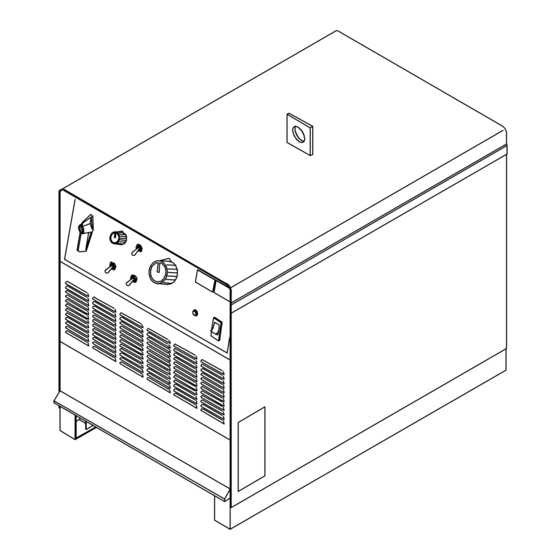
Description
Arc Welding Power Source
R
File: Stick (SMAW)
164 850AE
Advertisement
Table of Contents
Troubleshooting

Related Manuals for Miller Electric 302


Summary of Contents for Miller Electric 302
- Page 1 Visit our website at www.MillerWelds.com OM-222 2007−07 Processes Description Arc Welding Power Source 302, 452, 652 (60 Hz), 402, 602, 852 (50 Hz) 164 850AE TIG (GTAW) Welding Stick (SMAW) Welding Flux Cored (FCAW) Welding Air Carbon Arc (CAC-A) Cutting and Gouging...
- Page 2 ISO 9001:2000 Quality System Standard. particular model are also provided. Miller Electric manufactures a full line of welders and welding related equipment. For information on other quality Miller products, contact your local Miller distributor to receive the latest full line catalog or individual specification sheets.
-
Page 3: Table Of Contents
TABLE OF CONTENTS SECTION 1 − SAFETY PRECAUTIONS - READ BEFORE USING 1-1. Symbol Usage ............... . 1-2. - Page 4 European Community (CE) Products NOTE This information is provided for units with CE certification (see rating label on unit). Manufacturer: Miller Electric Mg. Co. 1635 W. Spencer St. Appleton, WI 54914 USA Phone: (920) 734-9821 European Contact Signature: Goldstar 402, 602, And 852...
-
Page 5: Section 1 − Safety Precautions - Read Before Using
DC constant voltage (wire) welder, 2) a DC manual (stick) welder, or 3) an AC welder with reduced open-circuit volt- age. In most situations, use of a DC, constant voltage wire welder is recommended. And, do not work alone! D Disconnect input power or stop engine before installing or servicing this equipment. - Page 6 OM-222 Page 2 D Do not use welder to thaw frozen pipes. D Remove stick electrode from holder or cut off welding wire at contact tip when not in use.
-
Page 7: Additional Symbols For Installation, Operation, And Maintenance
1-3. Additional Symbols For Installation, Operation, And Maintenance FIRE OR EXPLOSION hazard. D Do not install or place unit on, over, or near combustible surfaces. D Do not install unit near flammables. D Do not overload building wiring − be sure power supply system is properly sized, rated, and protected to handle this unit. -
Page 8: California Proposition 65 Warnings
1-4. California Proposition 65 Warnings Welding or cutting equipment produces fumes or gases which contain chemicals known to the State of California to cause birth defects and, in some cases, cancer. (California Health & Safety Code Section 25249.5 et seq.) Battery posts, terminals and related accessories contain lead and lead compounds, chemicals known to the State of California to cause cancer and birth defects or other... -
Page 9: Section 2 − Consignes De Sécurité − Lire Avant Utilisation
SECTION 2 − CONSIGNES DE SÉCURITÉ − LIRE AVANT UTILISATION Se protéger et protéger les autres contre le risque de blessure — lire et respecter ces consignes. 2-1. Symboles utilisés DANGER! − Indique une situation dangereuse qui si on l’évite pas peut donner la mort ou des blessures graves. Les dangers possibles sont montrés par les symboles joints ou sont expliqués dans le texte. - Page 10 Il reste une TENSION DC NON NÉGLIGEABLE dans les sources de soudage onduleur quand on a coupé l’alimentation. D Arrêter les convertisseurs, débrancher le courant électrique et décharger les condensateurs d’alimentation selon les instructions indiquées dans la partie Entretien avant de toucher les pièces. DES PIÈCES CHAUDES peuvent provoquer des brûlures graves.
-
Page 11: Dangers Supplémentaires En Relation Avec L'installation, Le Fonctionnement Et La Maintenance
ACCUMULATIONS risquent de provoquer des blessures ou même la mort. D Fermer l’alimentation du gaz protecteur en cas de non-utilisation. D Veiller toujours à bien aérer les espaces confi- nés ou se servir d’un respirateur d’adduction d’air homologué. LES CHAMPS MAGNETIQUES peuv- ent affecter des implants médicaux. -
Page 12: Proposition Californienne 65 Avertissements
LES FILS DE SOUDAGE peuvent provoquer des blessures. D Ne pas appuyer sur la gâchette avant d’en avoir reçu l’instruction. D Ne pas diriger le pistolet vers soi, d’autres per- sonnes ou toute pièce mécanique en enga- geant le fil de soudage. DES ORGANES MOBILES peuvent provoquer des blessures. -
Page 13: Principales Normes De Sécurité
2-5. Principales normes de sécurité Safety in Welding, Cutting, and Allied Processes, ANSI Standard Z49.1, de Global Engineering Documents (téléphone : 1-877-413-5184, site Internet : www.global.ihs.com). Recommended Safe Practices for the Preparation for Welding and Cut- ting of Containers and Piping, American Welding Society Standard AWS F4.1 de Global Engineering Documents (téléphone : 1-877-413-5184, site Internet : www.global.ihs.com). - Page 14 OM-222 Page 6...
-
Page 15: Section 3 − Definitions
SECTION 3 − DEFINITIONS 3-1. General Precautionary Label A complete Parts List is available at www.MillerWelds.com Warning! Watch Out! There are possible hazards as shown by the symbols. Electric shock from welding electrode or wiring can kill. 1.1 Wear dry insulating gloves. Do not touch electrode with bare hand. -
Page 16: Input Connection Label
A complete Parts List is available at www.MillerWelds.com 3-2. Input Connection Label Í Í Í Í Í Í 3-3. Electric Shock And Airflow Label 3-4. Nameplate Safety Symbols OM-222 Page 8 Í Í Í Í Í Í Í Í Í Warning! Watch Out! There are possible hazards as shown by the symbols. -
Page 17: Manufacturer's Rating Labels For Ce Products
A complete Parts List is available at www.MillerWelds.com 3-5. Manufacturer’s Rating Labels For CE Products Match label to one on unit. See Section 4-4. OM-222 Page 9... -
Page 18: Symbols And Definitions
A complete Parts List is available at www.MillerWelds.com 3-6. Symbols And Definitions Note Some symbols are found only on CE products. Amperes Temperature Output Protective Earth (Ground) Rated No Load Voltage (Average) Primary Current Degree Of Protection Wire Feeder 3-7. WEEE Label (For Products Sold Within The EU) OM-222 Page 10 Amperage Control/ Gas Tungsten Arc... -
Page 19: Section 4 − Installation
SECTION 4 − INSTALLATION 4-1. Specifications Maximum Rated Open- Model Model Welding Welding Range DC Range DC Circuit Circuit Output Voltage DC 300 A @ 32 Volts 15 − 395 DC, 60% (70) Duty Cycle 450 A @ 38 Volts 20 −... -
Page 20: Volt-Ampere Curves
A complete Parts List is available at www.MillerWelds.com 4-3. Volt-Ampere Curves A. 300 Amp Model B. 450 Amp Model C. 650 Amp Model OM-222 Page 12 Volt-ampere curves show mini- mum and maximum voltage and amperage output capabilities of unit. Curves of other settings fall be- tween curves shown. -
Page 21: Selecting A Location
4-4. Selecting A Location Movement Location And Airflow 18 in (460 mm) 18 in (460 mm) Lifting Eye Lifting Forks Use lifting eye or lifting forks to move unit. If using lifting forks, extend forks beyond opposite side of unit. Rating Label Location Use rating label to determine input power needs. -
Page 22: Dimensions And Weights
A complete Parts List is available at www.MillerWelds.com 4-5. Dimensions And Weights 300 Amp Models 30 in (762 mm) including lift eye 23 in (585 mm) 30-1/2 in (775 mm) including strain relief 27-1/2 in (699 mm) 3/4 in (19 mm) 21-1/8 in (537 mm) 1-1/8 in (29 mm) 7/16 in (11 mm) Dia... -
Page 23: Tipping
4-6. Tipping 4-7. 115 VAC Receptacle And Supplementary Protectors 4-8. Weld Output Terminals Do not move or operate unit where it could tip. Turn power before connecting to receptacle. 115 V 15 A AC Receptacle Power is shared between RC9 and Remote 14 receptacle RC8 (see Section 4-12). -
Page 24: Selecting Cable Sizes
A complete Parts List is available at www.MillerWelds.com 4-9. Selecting Cable Sizes Welding Amperes Weld cable size (AWG) is based on either a 4 volts or less drop or a current density of at least 300 circular mils per ampere. 4-10. -
Page 25: Remote 14 Receptacle Information
4-11. Remote 14 Receptacle Information 24 VOLTS AC 24 VOLTS AC REMOTE OUTPUT CONTROL 115 VOLTS AC 115 VOLTS AC REMOTE POWER ON/OFF REMOTE POWER ON/OFF REMOTE VOLTAGE SENSING REMOTE VOLTAGE SENSING * Not Used 4-12. Connecting Remote Control Socket 24 volts ac. -
Page 26: Electrical Service Guide
A complete Parts List is available at www.MillerWelds.com 4-13. Electrical Service Guide 60 Hertz Models Input Voltage Input Amperes At Rated Output Max Recommended Standard Fuse Rating In Amperes Time-Delay Normal Operating 3 Min Input Conductor Size In AWG Max Recommended Input Conductor Length In Feet (Meters) Min Grounding Conductor Size In Reference: 2005 National Electrical Code (NEC) -
Page 27: Placing Jumper Links
4-14. Placing Jumper Links 200 VOLTS 230 VOLTS 220 VOLTS (FACTORY OPTION) Tools Needed: 3/8 in 3/8 in 230 VOLTS 460 VOLTS 380 VOLTS 400 VOLTS Disconnect and lockout/tag- out input power before installing or moving jumper links. Check input voltage available at site. -
Page 28: Connecting Input Power
A complete Parts List is available at www.MillerWelds.com 4-15. Connecting Input Power L1 (U) L2 (V) L3 (W) Tools Needed: 3/8 in 3/8 in OM-222 Page 20 = GND/PE Earth Ground IMPORTANT Input Contactor GND/ PE Earth Ground Installation must meet all National and Local Codes −... -
Page 29: Section 5 − Operation
SECTION 5 − OPERATION 5-1. Controls (Non CE Models) Polarity Selector Switch (Optional On 50 Hz Models) To change polarity on models not equipped with a Polarity Selector switch, reverse work and electrode cables at the weld output termi- nals (see Section 4-9). Turn Off Power before reversing cables. -
Page 30: Controls (Ce Models)
A complete Parts List is available at www.MillerWelds.com 5-2. Controls (CE Models) Polarity Selector Switch (Optional On 50 Hz Models) To change polarity on models not equipped with a Polarity Selector switch, reverse work and electrode cables at the weld output termi- nals (see Section 4-9). -
Page 31: Section 6 − Maintenance And Troubleshooting
SECTION 6 − MAINTENANCE AND TROUBLESHOOTING 6-1. Routine Maintenance Disconnect power before maintaining. Maintain more often during severe conditions. n = Check Z = Change * To be done by Factory Authorized Service Agent Every Months nl Labels n~ Weld Terminals Every Months n lCables And Cords... -
Page 32: Troubleshooting
A complete Parts List is available at www.MillerWelds.com 6-3. Troubleshooting Trouble No weld output; unit completely inop- Place line disconnect switch in On position (see Section 4-15). erative. Check fuse F1, and replace if necessary (see Section 6-2). Check and replace line fuse(s), if necessary, or reset circuit breaker (see Section 4-15). Check for proper input power connections (see Section 4-15). - Page 33 A complete Parts List is available at www.MillerWelds.com Notes OM-222 Page 25...
-
Page 34: Circuit Diagram
SECTION 7 − ELECTRICAL DIAGRAM Figure 7-1. Circuit Diagram OM-222 Page 26... - Page 35 218 518-A OM-222 Page 27...
-
Page 36: Section 8 − Parts List
SECTION 8 − PARTS LIST NOTE A complete Parts List is available on-line at www.MillerWelds.com. 8-1. Recommended Spare Parts Dia. Part Mkgs. Description Quantity Recommended Spare Parts ....156 065 FUSE, crtg .5A 600V time delay . - Page 37 Notes...
- Page 38 Notes...
- Page 39 Warranty Questions? LIMITED WARRANTY − Subject to the terms and conditions Call below, Miller Electric Mfg. Co., Appleton, Wisconsin, warrants to 1-800-4-A-MILLER its original retail purchaser that new Miller equipment sold after the effective date of this limited warranty is free of defects in for your local material and workmanship at the time it is shipped by Miller.
-
Page 40: Owner's Record
File a claim for loss or damage during shipment. For assistance in filing or settling claims, contact your distributor and/or equipment manufacturer’s Transportation Department. 2007 Miller Electric Mfg. Co. 2007−01 Miller Electric Mfg. Co. An Illinois Tool Works Company 1635 West Spencer Street Appleton, WI 54914 USA International Headquarters−USA...
Need help?
Do you have a question about the 302 and is the answer not in the manual?
Questions and answers