Table of Contents
Advertisement
Visit our website at
www.MillerWelds.com
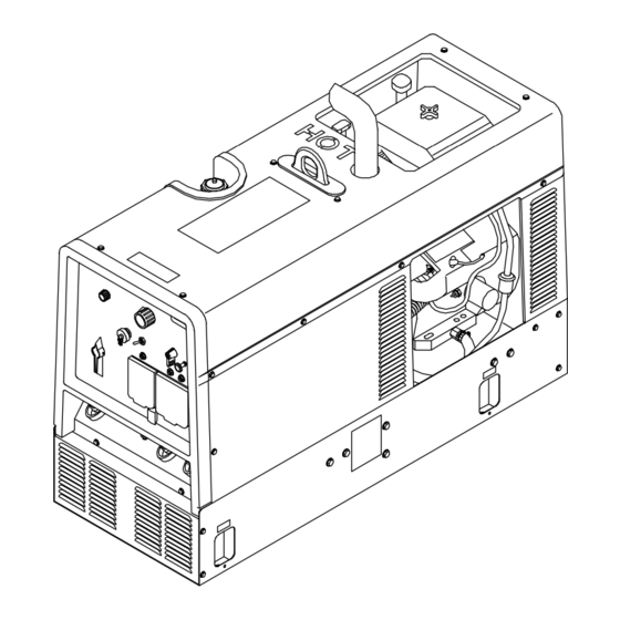
Trailblazer 301 G
Trailblazer DC
OM-4407
May 2004
Processes
MIG (GMAW) Welding
Flux Cored (FCAW)
Stick (SMAW) Welding
TIG (GTAW) Welding
Air Plasma Cutting and Gouging
R
with Spectrum
Unit
Air Carbon Arc (CAC-A) Cutting
and Gouging
Description
Engine Driven Welding Generator
(AC Available On AC/DC Models Only)
R
R
203 236U
Advertisement
Table of Contents
Troubleshooting

Related Manuals for Miller Electric 301 G, DC


Summary of Contents for Miller Electric 301 G, DC
- Page 1 Visit our website at www.MillerWelds.com Trailblazer 301 G Trailblazer DC OM-4407 203 236U May 2004 Processes MIG (GMAW) Welding Flux Cored (FCAW) Stick (SMAW) Welding TIG (GTAW) Welding Air Plasma Cutting and Gouging with Spectrum Unit Air Carbon Arc (CAC-A) Cutting and Gouging Description Engine Driven Welding Generator...
- Page 2 ISO 9001:2000 Quality System Standard. particular model are also provided. Miller Electric manufactures a full line of welders and welding related equipment. For information on other quality Miller products, contact your local Miller distributor to receive the latest full line catalog or individual catalog sheets.
-
Page 3: Table Of Contents
TABLE OF CONTENTS SECTION 1 − SAFETY PRECAUTIONS − READ BEFORE USING 1-1. Symbol Usage ............... . 1-2. - Page 4 TABLE OF CONTENTS SECTION 8 − MAINTENANCE (Robin EH64-POWERED UNITS) 8-1. Maintenance Label (Robin EH64-Powered Units) 8-2. Routine Maintenance (Robin EH64-Powered Units) 8-3. Servicing Air Cleaner (Robin EH64-Powered Units) 8-4. Servicing Optional Spark Arrestor (Robin EH64-Powered Units) 8-5. Overload Protection (Robin EH64-Powered Units) 8-6.
-
Page 5: Section 1 − Safety Precautions − Read Before Using
SECTION 1 − SAFETY PRECAUTIONS − READ BEFORE USING Y Warning: Protect yourself and others from injury — read and follow these precautions. 1-1. Symbol Usage Means Warning! Watch Out! There are possible hazards with this procedure! The possible hazards are shown in the adjoining symbols. -
Page 6: Noise Can Damage Hearing
WELDING can cause fire or explosion. Welding on closed containers, such as tanks, drums, or pipes, can cause them to blow up. Sparks can fly off from the welding arc. The flying sparks, hot workpiece, and hot equipment can cause fires and burns. Accidental contact of electrode to metal objects can cause sparks, explosion, overheating, or fire. -
Page 7: Compressed Air Hazards
STEAM AND HOT COOLANT can burn. D If possible, check coolant level when engine is cold to avoid scalding. D Always check coolant level at overflow tank, if pres- ent on unit, instead of radiator (unless told otherwise in maintenance section or engine manual). D If the engine is warm, checking is needed, and there is no overflow tank, follow the next two statements. -
Page 8: California Proposition 65 Warnings
READ INSTRUCTIONS. D Use only genuine MILLER/Hobart replacement parts. D Perform engine and air compressor (if applicable) maintenance and service according to this manual and the engine/air compressor (if applicable) manu- als. H.F. RADIATION can cause interference. D High-frequency (H.F.) can interfere with radio naviga- tion, safety services, computers, and communica- tions equipment. -
Page 9: Section 2 − Consignes De Sécurité − Lire Avant Utilisation
SECTION 2 − CONSIGNES DE SÉCURITÉ − LIRE AVANT Y Avertissement: Protégez vous et les autres des blessures − lisez et suivez ces précautions. 2-1. Signification des symboles Signifie Mise en garde ! Soyez vigilant ! Cette procédure présente des risques de danger ! Ceux-ci sont identifiés par des symboles adjacents aux directives. -
Page 10: Dangers Existant En Relation Avec Le Moteur
LES ACCUMULATIONS DE GAZ ris- quent de provoquer des blessures ou même la mort. D Fermer l’alimentation du gaz protecteur en cas de non utilisation. D Veiller toujours à bien aérer les espaces confinés ou se servir d’un respi- rateur d’adduction d’air homologué. LES RAYONS DE L’ARC peuvent pro- voquer des brûlures dans les yeux et sur la peau. -
Page 11: Dangers Liés À L'air Comprimé
L’EXPLOSION DE LA BATTERIE peut RENDRE AVEUGLE. D Toujours porter une protection faciale, des gants en caoutchouc et vêtements de protection lors d’une in- tervention sur la batterie. D Arrêter le moteur avant de débrancher ou de brancher les câbles de batterie. -
Page 12: Principales Normes De Sécurité
LE SURCHAUFFEMENT peut endom- mager le moteur électrique. D Arrêter ou déconnecter l’équipement avant de dé- marrer ou d’arrêter le moteur. D Ne pas laisser tourner le moteur trop lentement sous risque d’endommager le moteur électrique à cause d’une tension et d’une fréquence trop faibles. D Ne pas brancher de moteur de 50 ou de 60 Hz à... -
Page 13: Section 3 − Definitions
SECTION 3 − DEFINITIONS 3-1. Symbol Definitions Stop Engine Start Engine Engine Oil Engine MIG (GMAW), Wire Positive Time Do not switch while welding Wire Feed Notes Fast Fast/Slow (Run, Weld/Power) (Run/Idle) Panel/Local Temperature Check Valve Engine Choke Clearance Read Operator’s Amperes Manual Stick (SMAW) -
Page 14: Section 4 − Specifications
SECTION 4 − SPECIFICATIONS 4-1. Weld, Power, And Engine Specifications Rated Maximum Welding Welding Open-Circuit Mode Output Voltage 280 A, 25 V, 100% CC/DC Duty Cycle 300 A, 25 V, 100% CV/DC Duty Cycle 200 A, 25 V, 60% CC/AC* Duty Cycle AC/DC Models Only. -
Page 15: Fuel Consumption While Welding
4-3. Fuel Consumption While Welding 8.51 2.25 7.57 2.00 6.62 1.75 5.68 1.50 1.25 4.73 3.79 1.00 2.84 0.75 1.89 0.50 IDLE − KOHLER AND ROBIN 0.95 0.25 0.00 0.00 DC WELD AMPERES AT 100% DUTY CYCLE 4-4. Fuel Consumption While Using Generator Power 8.51 2.25 7.57... -
Page 16: Generator Power Curve
4-5. Generator Power Curve 4-6. Duty Cycle 100% Duty Cycle at 280 Amperes DC OM-4407 Page 12 10,000 watts AC AMPERES Continuous Welding MIG/FCAW STICK AC WELD % DUTY CYCLE The ac generator power curve shows the generator power avail- able in amperes at the receptacles. -
Page 17: Stick And Mig Mode Volt-Ampere Curves
4-7. Stick And MIG Mode Volt-Ampere Curves A. CC/AC Stick Mode B. CC/DC Stick Mode C. CV/DC MIG Mode AC AMPERES DC AMPERES DC AMPERES The volt-ampere curves show the minimum and maximum voltage and amperage output capabilities of the welding generator. Curves of other settings fall between the curves shown. -
Page 18: Tig Mode Volt-Ampere Curves
4-8. TIG Mode Volt-Ampere Curves A. CC/AC TIG Mode B. CC/DC TIG Mode OM-4407 Page 14 AC AMPERES DC AMPERES The volt-ampere curves show the minimum and maximum voltage and amperage output capabilities of the welding generator. Curves of other settings fall between the curves shown. -
Page 19: Section 5 − Installation
SECTION 5 − INSTALLATION 5-1. Installing Welding Generator Movement Y Do not lift unit from end. Location Mounting Inadequate support. Y Do not use flexible mounts. Grounding GND/PE Airflow Clearance 18 in (460 mm) 18 in (460 mm) Electrically bond generator frame to vehicle frame by metal-to-metal contact. -
Page 20: Engine Prestart Checks (Robin Eh64-Powered Units)
5-2. Engine Prestart Checks (Robin EH64-Powered Units) Full Gasoline OM-4407 Page 16 Oil Check Oil Fill Full Check all fluids daily. Engine must be cold and on a level surface. Unit is shipped with 10W30 engine oil. Follow run-in procedure in en- gine manual. -
Page 21: Engine Prestart Checks (Kohler-Powered Units)
5-3. Engine Prestart Checks (Kohler-Powered Units) Full Gasoline Full Check all fluids daily. Engine must be cold and on a level surface. Unit is shipped with 10W30 engine oil. Follow run-in procedure in engine manual. This unit has a low oil pressure shutdown switch. -
Page 22: Activating The Dry Charge Battery (If Applicable)
5-4. Activating The Dry Charge Battery (If Applicable) 5 A For 30 Minutes 30 A For 12 Minutes OM-4407 Page 18 − Remove battery from unit. Eye Protection − Safety Glasses Or Face Shield Rubber Gloves Vent Caps Sulfuric Acid Electrolyte (1.265 Specific Gravity) Well Fill each cell with electrolyte to... -
Page 23: Connecting The Battery
5-5. Connecting The Battery Tools Needed: 3/8, 1/2 in 5-6. Installing Exhaust Pipe Tools Needed: 1/2 in Y Connect negative (−) cable last. − Ref. 800 394-C / Ref. 206 422 / Ref. S-0756-D Y Stop engine and let cool. Y Engine backfire can cause se- vere burns or other injuries. -
Page 24: Connecting To Weld Output Terminals
5-7. Connecting To Weld Output Terminals OM-4407 Page 20 Y Stop engine. Y Do not connect to CC and CV terminals at the same time. AC/DC Models: Work Weld Output Terminal Stick/TIG (CC) Weld Output Terminal Wire /CV Weld Output Terminal For MIG welding, connect work cable to Work terminal and wire feeder cable to Wire (CV) terminal. -
Page 25: Selecting Weld Cable Sizes
5-8. Selecting Weld Cable Sizes* Weld Output Terminals Y Stop engine before Welding connecting to weld out- Amperes put terminals. Y Do not use worn, dam- aged, undersized, or poorly spliced cables. This chart is a general guideline and may not suit all applications. If cable overheats, use next size larger cable. **Weld cable size (AWG) is based on either a 4 volts or less drop or a current density of at least 300 circular mils per ampere. -
Page 26: Adjusting Wire (Mig) Weld Puddle Consistency
5-10. Adjusting Wire (MIG) Weld Puddle Consistency Tools Needed: 3/8, 7/16 in OM-4407 Page 22 Y Stop engine and let cool. Stabilizer DC-Z is factory connected to suit most Wire (MIG) welding applications. To change Wire (MIG) weld puddle consis- tency, proceed as follows: Remove cover and right side panel. -
Page 27: Section 6 − Operating Welding Generator
SECTION 6 − OPERATING WELDING GENERATOR 6-1. Front Panel Controls Process/Contactor Switch See Section 6-2 for Process/Contactor switch information. Voltage/Amperage Adjust Switch And Remote Receptacle Use switch to select front panel or remote voltage/amperage control. For remote con- trol, place switch in Remote position and connect remote control to Remote recep- tacle RC4 (see Sections 5-9 and 6-3). -
Page 28: Process/Contactor Switch On Cc/Cv Models
6-2. Process/Contactor Switch On CC/CV Models Switch Setting Switch Setting GTAW With HF Unit, Pulsing Device, Or Remote − TIG Remote − Stick Stick (SMAW) With Remote On/Off Remote − Wire Electrode Hot − Wire Electrode Hot − Stick Air Carbon Arc (CAC-A) Cutting And Gouging Electrode Hot −... -
Page 29: Remote Amperage/Voltage Control
6-3. Remote Amperage/Voltage Control Set V/A Adjust Select Polarity By Switch Using DC Polarity/AC Switch (If Present) Or By Changing Cable Connections Switch present on AC/DC models only. A/V Control Remote Receptacle RC4 Connect optional remote control to RC4 (see Section 5-9). Remote Hand Control (Optional) Remote Foot Control (Optional) Engine runs at weld/power speed... -
Page 30: Section 7 − Operating Auxiliary Equipment
SECTION 7 − OPERATING AUXILIARY EQUIPMENT 7-1. Generator Power Receptacles And Circuit Breakers OM-4407 Page 26 Y If unit does not have GFCI re- RC1 supplies 60 Hz single-phase power at weld/power speed. Maxi- mum output is 9.5 kVA/kW. RC2 and RC3 supply 60 Hz single- phase power at weld/power speed. -
Page 31: Optional Generator Power Receptacles
7-2. Optional Generator Power Receptacles Notes Y If unit does not have GFCI re- ceptacles, protected extension cord. Generator power decreases as weld current increases. Combined output of all receptacles limited to 8 kVA/kW rating of the generator. GFCI Receptacle Option 120 V 20 A AC GFCI Recep- tacles GFCI-2 and GFCI-3 GFCI2 and GFCI3 supply 60 Hz... -
Page 32: Wiring Instructions For Optional 240 Volt, Single-Phase Plug (Nema 14-50P)
7-3. Wiring Instructions For Optional 240 Volt, Single-Phase Plug (NEMA 14-50P) Current Available in Amperes 240 V Each 120 V Duplex Receptacle* Receptacle V x A = Watts *One 240 V load or two 120 V loads. OM-4407 Page 28 120V 120V 240V... -
Page 33: Section 8 − Maintenance (Robin Eh64-Powered Units)
SECTION 8 − MAINTENANCE (Robin EH64-POWERED UNITS) 8-1. Maintenance Label (Robin EH64-Powered Units) OM-4407 Page 29... -
Page 34: Routine Maintenance (Robin Eh64-Powered Units)
8-2. Routine Maintenance (Robin EH64-Powered Units) Note Follow the storage procedure in the engine owner’s manual if the unit will not be used for an extended period. Check fluid levels. See Section 5-2. Every 20 h Check clean spark arrestor screen. See Section 8-4. - Page 35 Change oil filter. See Section maintenance label. Repair or replace cracked cables. Every 200 h Replace fuel filter. Section 8-6. Check spark plugs. Replace unreadable labels. Every 500 h Service welding generator brushes and slip rings. Service more often in dirty conditions.* Check valve clearance.*...
-
Page 36: Servicing Air Cleaner (Robin Eh64-Powered Units)
8-3. Servicing Air Cleaner (Robin EH64-Powered Units) 8-4. Servicing Optional Spark Arrestor (Robin EH64-Powered Units) Tools Needed: 1/4 in OM-4407 Page 32 Y Stop engine. Y Do not run engine without air cleaner or with dirty element. Wrapper (Foam Element) Wash wrapper with soap and water solution. -
Page 37: Overload Protection (Robin Eh64-Powered Units)
8-5. Overload Protection (Robin EH64-Powered Units) Located behind front panel. Tools Needed: 3/8 in Y Stop engine. When a circuit breaker or fuse opens, it usually indicates a more serious problem exists. Contact a Factory Authorized Service Agent. Circuit Breaker CB5 CB5 protects the 24 volt ac output to Remote receptacle RC4. -
Page 38: Changing Engine Oil, Oil Filter, And Fuel Filter (Robin Eh64-Powered Units)
8-6. Changing Engine Oil, Oil Filter, and Fuel Filter (Robin EH64-Powered Units) Oil Check Full Tools Needed: OM-4407 Page 34 Oil Fill Y Stop engine and let cool. Oil Drain Valve Oil Filter Change engine oil and filter accord- ing to engine owner’s manual. Y Close valve and valve cap before adding... -
Page 39: Adjusting Engine Speed (Robin Eh64-Powered Units)
8-7. Adjusting Engine Speed (Robin EH64-Powered Units) Tools Needed: 10 mm 8 mm 2200 100 rpm 3700 50 rpm After tuning engine, check engine speeds with a tachometer (see table). If necessary, adjust speeds as follows: Start engine and run until warm. Remove wrapper to access speed adjustments. -
Page 40: Section 9 − Maintenance (Kohler-Powered Units)
SECTION 9 − MAINTENANCE (KOHLER-POWERED UNITS) 9-1. Routine Maintenance (Kohler-Powered Units) Check fluid levels. See Section 5-3. Every 20 h Check and clean spark arrestor screen. See Section 9-4. Clean and tighten weld terminals. Change oil. See Section 9-5 and maintenance label. -
Page 41: Maintenance Label (Kohler-Powered Units)
9-2. Maintenance Label (Kohler-Powered Units) NOTE Follow the storage procedure in the engine owner’s manual if the unit will not be used for an extended period. OM-4407 Page 37... -
Page 42: Servicing Air Cleaner (Kohler-Powered Units)
9-3. Servicing Air Cleaner (Kohler-Powered Units) 9-4. Servicing Optional Spark Arrestor (Kohler-Powered Units) Tools Needed: 1/4 in OM-4407 Page 38 Y Stop engine. Y Do not run engine without air cleaner or with dirty element. Wrapper (Foam Element) Wash wrapper with soap and water solution. -
Page 43: Changing Engine Oil, Oil Filter, And Fuel Filter (Kohler-Powered Units)
9-5. Changing Engine Oil, Oil Filter, And Fuel Filter (Kohler-Powered Units) Full Tools Needed: Y Stop engine and let cool. Oil Drain Valve Oil Filter Change engine oil and filter accord- ing to engine manual. Y Close valve and valve cap before adding oil and run- ning engine. -
Page 44: Adjusting Engine Speed (Kohler-Powered Units)
9-6. Adjusting Engine Speed (Kohler-Powered Units) Tools Needed: 1/4, 3/8 in OM-4407 Page 40 2200 3700 Top View After tuning engine, check engine speeds with a tachometer (see table). If necessary, adjust speeds as follows: Start engine and run until warm. 50 rpm Turn A/V control to 10. -
Page 45: Overload Protection (Kohler-Powered Units)
9-7. Overload Protection (Kohler-Powered Units) Located behind front panel. Tools Needed: 3/8 in Y Stop engine. When a circuit breaker or fuse opens, it usually indicates a more serious problem exists. Contact a Factory Authorized Service Agent. Circuit Breaker CB5 CB5 protects the 24 volt ac output to Remote receptacle RC4. -
Page 46: Section 10 − Troubleshooting
SECTION 10 − TROUBLESHOOTING 10-1. Welding Troubleshooting Trouble No weld output. Check control settings. Check weld connections. Disconnect equipment from generator power receptacles during start-up. Place V/A Adjust switch in Panel position, or move switch to Remote position and connect remote control to Remote receptacle RC4 (see Sections 5-9 and 6-1). -
Page 47: Generator Power Troubleshooting
Trouble Lack of high frequency; difficulty in Use proper size tungsten for welding amperage. establishing Gas Tungsten Arc Weld- ing arc. Reduce leakage of high frequency from torch or work cable (check grounding, remove excessive coils from weld cables, use shorter weld cables, etc.). Check cables and torch for cracked or deteriorated insulation or bad connections. - Page 48 Trouble Engine does not start. Check fuel level (see Section 5-2 or 5-3). Check battery and replace if necessary. Check engine charging system according to engine manual. Have Factory Authorized Service Agent check fuel shutoff solenoid GS1 according to engine manual (GS1 standard on Kohler-powered units;...
- Page 49 Notes Work like a Pro! Pros weld and cut safely. Read the safety rules at the beginning of this manual. OM-4407 Page 45...
-
Page 50: Section 11 − Electrical Diagrams
SECTION 11 − ELECTRICAL DIAGRAMS Figure 11-1. Circuit Diagram For Welding Generator Models With AC/DC Output OM-4407 Page 46... - Page 51 209 625-C OM-4407 Page 47...
- Page 52 Figure 11-2. Circuit Diagram For Welding Generator Models With DC Output Only (Kohler Only) OM-4407 Page 48...
- Page 53 209 620-B OM-4407 Page 49...
-
Page 54: Section 12 − Generator Power Guidelines
SECTION 12 − GENERATOR POWER GUIDELINES NOTE The views in this section are intended to be representative of all engine-driven welding generators. Your unit may differ from those shown. 12-1. Selecting Equipment 12-2. Grounding Generator To Truck Or Trailer Frame Electrically bond generator frame to vehicle frame by metal-to-metal contact. -
Page 55: Grounding When Supplying Building Systems
12-3. Grounding When Supplying Building Systems 12-4. How Much Power Does Equipment Require? AMPERES x VOLTS = WATTS EXAMPLE 1: If a drill uses 4.5 amperes at 115 volts, calculate its running power requirement in watts. The load applied by the drill is 520 watts. EXAMPLE 2: If three 200 watt flood lamps are used with the drill from Example 1, add the individual loads to calculate total load. - Page 56 12-5. Approximate Power Requirements For Industrial Motors Industrial Motors Split Phase Capacitor Start-Induction Run Capacitor Start-Capacitor Run Fan Duty 12-6. Approximate Power Requirements For Farm/Home Equipment Farm/Home Equipment Stock Tank De-Icer Grain Cleaner Portable Conveyor Grain Elevator Milk Cooler Milker (Vacuum Pump) FARM DUTY MOTORS Std.
- Page 57 12-7. Approximate Power Requirements For Contractor Equipment Contractor Hand Drill Circular Saw Table Saw Band Saw Bench Grinder Air Compressor Electric Chain Saw Electric Trimmer Electric Cultivator Elec. Hedge Trimmer Flood Lights Submersible Pump Centrifugal Pump Floor Polisher High Pressure Washer 55 gal Drum Mixer Wet &...
-
Page 58: Power Required To Start Motor
12-8. Power Required To Start Motor Single-Phase Induction Motor Starting Requirements Motor Start Code KVA/HP kVA/HP x HP x 1000 VOLTS EXAMPLE: Calculate the starting amperage required for a 230 V, 1/4 HP motor with a motor start code of M. Volts = 230 HP = 1/4 11.2 x 1/4 x 1000... - Page 59 12-10. Typical Connections To Supply Standby Power Y Properly install and ground this equipment according to its Owner’s Manual and national, state, and local codes. Utility Electrical Service Y Have only qualified persons perform these connections according to all applicable codes and safety practic- Y Properly install and ground this equipment according to its Owner’s Manual and national, state, and local...
-
Page 60: Selecting Extension Cord (Use Shortest Cord Possible)
12-11. Selecting Extension Cord (Use Shortest Cord Possible) Cord Lengths for 120 Volt Loads Y If unit does not have GFCI receptacles, use GFCI-protected extension cord. Current Load (Watts) (Amperes) 1200 1800 2400 3000 3600 4200 4800 5400 6000 *Conductor size is based on maximum 2% voltage drop Cord Lengths for 240 Volt Loads Y If unit does not have GFCI receptacles, use GFCI-protected extension cord. - Page 61 Notes OM-4407 Page 57...
-
Page 62: Section 13 − Parts List
SECTION 13 − PARTS LIST Hardware is common and not available unless listed. 802 951 Figure 13-1. Main Assembly (Kohler Engine Shown) OM-4407 Page 58... - Page 63 Item Dia. Part Mkgs....182367 ....185352 ..
- Page 64 Item Dia. Part Mkgs....168385 ....+201174 ..
- Page 65 Item Dia. Part Mkgs..... 206537 ..PLG15 . . . 115092 ..
- Page 66 Hardware is common and not available unless listed. OM-4407 Page 62 Figure 13-2. Panel, Front w/Components 802 952...
- Page 67 Item Dia. Part Mkgs....206854 ....115 440 .
- Page 68 Item Part ....+206 406 ....182092 ..
- Page 71 Warranty Questions? Call LIMITED WARRANTY − Subject to the terms and conditions below, Miller Electric Mfg. Co., Appleton, Wisconsin, warrants to 1-800-4-A-MILLER its original retail purchaser that new Miller equipment sold after for your local the effective date of this limited warranty is free of defects in material and workmanship at the time it is shipped by Miller.
-
Page 72: Owner's Record
File a claim for loss or damage during shipment. For assistance in filing or settling claims, contact your distributor and/or equipment manufacturer’s Transportation Department. 2003 Miller Electric Mfg. Co. 1/03 Miller Electric Mfg. Co. An Illinois Tool Works Company 1635 West Spencer Street Appleton, WI 54914 USA International Headquarters−USA...
Need help?
Do you have a question about the 301 G, DC and is the answer not in the manual?
Questions and answers