Table of Contents
Advertisement
Advertisement
Table of Contents

Related Manuals for Opticum HD 9600


Summary of Contents for Opticum HD 9600
-
Page 2: Table Of Contents
Contents Safety precautions ........................1 Environment protection ........................ 3 Operating notes ..........................4 3.1. Automatic Power Down ......................4 3.2. Working with external USB drive (only for receivers with USB connector) ......4 3.3. Battery installation ......................... 5 Features ............................6 Remote control .......................... -
Page 3: Safety Precautions
1. Safety precautions CAUTION: lightning flash with Warning: The exclamation point within an arrowhead symbol, within an equilateral triangle is intended to To reduce the risk of electric shock, equilateral triangle, alert the user to important don't open the cabinet. Refer intended to alert the user to operating maintenance... - Page 4 Attachments: Never add any attachments and/or equipment without the manufacturer consent; as such additions may result in the risk of fire, electric shock, or other personal injury. Locating: Slots and openings in the cabinet are provided for ventilation to protect it from overheating. Do not block these openings or allow them to be blocked by placing the STB on a bed, sofa, or other similar surface, nor should it be placed over a radiator or heat register.
-
Page 5: Environment Protection
2. Environment protection Attention! Your product Is marked with this symbol. It means that used electrical and electronic products should not be mixed with general household waste. There is a separate collection system for these products. Information on Disposal for Users (private households) in the European Union Used electrical and electronic equipment must be treated separately and In accordance with legislation that requires proper treatment, recovery and recycling of used electrical and electronic equipment. -
Page 6: Operating Notes
3. Operating notes NOTE! 3.1. Automatic Power Down In accordance with actual European Union requirements, Your receiver is equipped with function "Automatic Power Off". It works by switching the receiver into standby mode after a period of 3 hours after the last active use. In practice this means that if during this time the receiver will not be given any command by using the remote control or keypad on the front panel, the receiver turns off. -
Page 7: Battery Installation
3.3. Battery installation To install the batteries in the remote control, remove flap protecting battery compartment (see Fig.: A – slider type - push and slide, B – latch type - lever the latch and pull the fold). If inside the chamber there are used batteries, they must be removed. -
Page 8: Features
4. Features • SD / HD support (MPEG4 AVC/H.264) • Common Interface Slot (optionally 2) • Card Reader (optionally 2) • High Definition Video output: HDMI and YPbPr (optionally) • Front panel display – VFD or LED • Channel sorting by Satellite, Alphabetic order & Network FTA, CAS •... -
Page 9: Remote Control
5. Remote control BUTTON FUNCTION POWER Switch receiver between Operation and Standby mode. HELP (Optional function) TV format Switch the TV Standard of the Screen. If you have problem with video format setting, switch this button until set the best video resolution Numeric Select the TV or Radio services and menu options. -
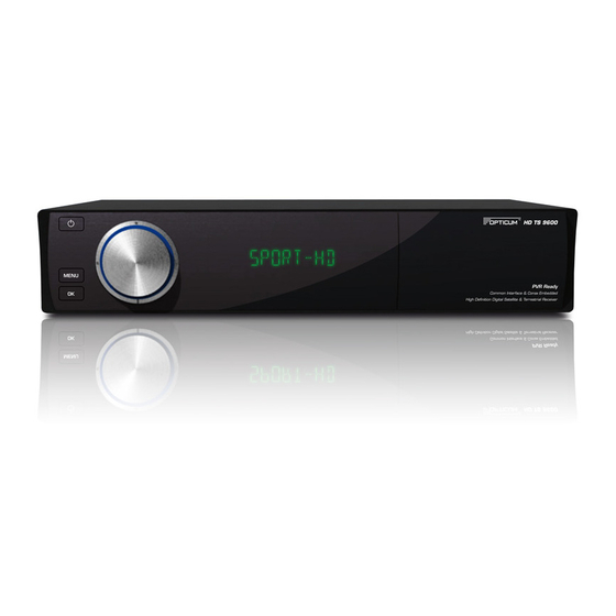
Page 10: Front Panel
6. Front panel 1.Power button: Switch receiver between standby and working mode. 2.MENU button: Display menu on screen or return to previous menu. 3.OK button: Display channel list on screen, select item in menu. 4.VOL-/VOL + buttons: Decrease / increase sound volume. 5.CH-/CH+ buttons: Switch to previous / next channel. -
Page 11: Rear Panel
7. Rear panel Please refer to the diagram above for all possible connections of your receiver. Do not connect the unit to the mains socket until all other connections have been made and checked. Your configuration can vary depending on model LNB IN: Connector to coaxial cable from LNB of dish - 500mA max. -
Page 12: Connecting
8. Connecting 8.1. Connecting receiver to TV set using HDMI cable Connect the coaxial cable to “LNB IN” terminal marked at the rear of the receiver. Connect HDMI cable to HDMI ports of TV and receiver. 8.2. Connecting receiver to TV set using component cable (optional) Connect the coaxial cable to “LNB IN”... -
Page 13: Connecting Receiver To Tv Set Using Scart Cable (Optional)
8.3. Connecting receiver to TV set using SCART cable (optional) Connect the coaxial cable to “LNB IN” terminal marked at the rear of the receiver. Connect the SCART cable to port “SCART” of Receiver to the respective SCART port of TV 8.4. -
Page 14: Menu Operations
9. Menu operations This chapter assumes that the HD Receiver system has been installed correctly, meaning: • The antenna for the receiver is installed and connected to the receiver. • The receiver is connected to the TV. • Batteries are installed in remote controller unit (RCU) and RCU is ready to control the receiver. - Page 15 channel list by ↑,↓ buttons. Another press of Move button accepts actual, new channel position. Rename (Black button): Enables channel name changing by screen keyboard. User can choose letter from keyboard by cursor buttons and accept it by OK button. When using keyboard, functions of color buttons are different.
-
Page 16: Menu „Installation
9.2. Menu „Installation” Menu „Installation” includes 5 submenu items: • Automatic search satellite • Manual search satellite • Automatic search terrestrial (optional) • Manual search terrestrial (optional) • Default Setting 9.2.1. Automatic search satellite This function enables quick way to scan satellite channels. Automatic search satellite screen consist at beginning only satellite list. -
Page 17: Menu „User Setup
This function enables quick way to scan terrestrial channels. User can define here: Region: Depending on region, some parameters of broadcast are different. User should use specific setting according to localization. RF channel: Defines reference channel – signal strength and quality of this channel will be showed on bars on right side of window. -
Page 18: Parental Control
This menu contains: Time Setting: Defines time mode. If user choose “Auto”, time will be taken from broadcast. Then user also must define time offset accordingly to localization. If user choose “Manual”, also must define date and time manually using below functions: Summer Time: In auto mode, enables additional time offset for summer time. -
Page 19: Menu „Multimedia
AC3: Enables AC3 sound tracks. 9.3.5. OSD Setting The user can adjust the display time (time of the appearing of the info bar) and the OSD transparency (in %) on top of video signal of the receiver. 9.3.6. Automatic Power Down This function enables to set time which after receiver without user intervention will automatically go to standby mode, or enables to switch off Automatic Power Down mode. -
Page 20: Menu „Common Interface
9.5. Menu „Common Interface” Menu „Common Interface” includes 1 (optional 2) submenu item: • Common Interface (Up) • Common Interface Down (optional) Receiver is equipped with one (optional two) slot for Common Interface (CI) modules. To install CI set: − Open the flap on the front panel of the product. -
Page 21: Menu „System
9.7. Menu „System” Menu „System” includes 4 submenu items: • Information • Software Upgrade • Default Setting • 9.7.1. Information This menu is used to get information about the receiver and its hardware, software and loader. 9.7.2. Software Upgrade This menu is used to update actual receiver’s software. Color buttons filter files according to content (Firmware, Channel Data, All) and enables to make channel list backup. -
Page 22: Function Guide
10. Function guide 10.1. Channel list Press OK button to display Channel list. Buttons ↑,↓ enables changing cursor position on the list. OK button pressed on selected channel, switch actual channel to selected one. Press one of color button on remote to call corresponding function: Group (Red button): Limits displayed list of channels to specified groups: All TV,... -
Page 23: Information Bar
10.3. Information bar Press INFO button to display Information bar. Information bar content: • Index and name of actual channel, • Actual time, • Event progress bar, • EPG info about Now event, • EPG info about Next event, • Status icons of channel (HD, scrambled, locked, subtitles, teletext,... -
Page 24: Direct Recording
10.10. Direct recording To start a recording press the REC key, choose a duration with the ←,→ keys and confirm with the OK key. 10.11. EPG Recording Via the EPG you can program a Timer reservation – Please also see “9.2. EPG Browser” for more details. -
Page 25: Technical Specification
Storage Temperature -10℃~+70℃ Storage Humidity 5%~95% RH (Non-Condensing) - Applies to HD 9600 Prima receiver ** - Applies to HD TS 9600 Prima receiver Weight and dimensions are not absolutely exact values. Specifications are subject to change (by manufacturer) without notice.
Need help?
Do you have a question about the HD 9600 and is the answer not in the manual?
Questions and answers