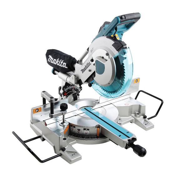
Makita LS1016 Instruction Manual
Slide compound miter saw
Hide thumbs
Also See for LS1016:
- Instruction manual (152 pages) ,
- Technical information (37 pages) ,
- Instruction manual (8 pages)

Related Manuals for Makita LS1016


Summary of Contents for Makita LS1016
- Page 1 INSTRUCTION MANUAL Slide Compound Miter Saw LS1016 LS1016L LS1016F LS1016FL 009482 DOUBLE INSULATION IMPORTANT: Read Before Using.
-
Page 2: Specifications
1.6 mW (Laser Class 2M) Dimensions (L x W x H) 718 mm x 640 mm x 671 mm Net weight For all countries other than European countries LS1016 …..23.6 kg LS1016L/LS1016F …..23.7 kg LS1016FL.….23.8 kg For European countries LS1016 ….24.1 kg LS1016L/LS1016F …..24.2 kg... -
Page 3: General Power Tool Safety Warnings
Designation of Machine: their life must be collected separately and Slide Compound Miter Saw returned to an environmentally compatible Model No./ Type: LS1016, LS1016L, LS1016F, recycling facility. LS1016FL ENE006-1 Conforms to the following European Directives:... - Page 4 Keep children and bystanders away while 15. Do not overreach. Keep proper footing and operating a power tool. Distractions can cause balance at all times. This enables better control you to lose control. of the power tool in unexpected situations. Electrical safety 16.
- Page 5 ENB034-10 23. Never reach around saw blade. 24. Turn off tool and wait for saw blade to stop before MITER SAW SAFETY WARNINGS moving workpiece or changing settings. Keep hands out of path of saw blade. Avoid Unplug tool before changing blade or servicing. contact with any coasting blade.
-
Page 6: Functional Description
work. To reduce your exposure to these FUNCTIONAL DESCRIPTION chemicals: work in a well ventilated area and work with approved safety equipment, such as those dust masks that are specially designed WARNING: to filter out microscopic particles. Always be sure that the tool is switched off and •... - Page 7 UV light screw counterclockwise which secures the upper slide poles exposure, contact a Makita service center for a new and also push forward the lock lever which secures the lower guard. DO NOT DEFEAT OR REMOVE GUARD.
-
Page 8: Adjusting The Bevel Angle
figure. Adjust the adjusting screw so that the blade stops 1. Top surface of at the desired position when lowering the handle fully. turn base Adjusting the miter angle 2. Periphery of blade 3. Guide fence 1. Lock lever 2. Grip 3. - Page 9 Switch action 1. Scale plate For European countries 2. Release button 3. Pointer 1. Lock-off button 4. Latch lever 2. Switch trigger 3. Lever 4. Hole for padlock 009513 Tilt the saw blade until the pointer points to the desired angle on the bevel scale.
-
Page 10: Soft Start Feature
A switch in need of repair may result in unintentional operation and serious personal For models LS1016L and LS1016FL only injury. Return tool to a Makita service center for 1. Switch for laser proper repairs BEFORE further usage. - Page 11 Shift the laser line to the left of the blade. • Use only the Makita hex wrench provided to • B) When you obtain the correct size on the right side of install or remove the blade. Failure to use the...
- Page 12 NOTE: 1. Center cover If the inner flange is removed be sure to install it on • 2. Hex wrench the spindle with its protrusion facing away from the 3. Hex socket bolt blade. If the flange is installed incorrectly the 4.
- Page 13 Accidental start up of the tool may result in 3. Blade case serious personal injury. 4. Saw blade Use only the Makita socket wrench provided to • install or remove the blade. Failure to use the wrench may result in overtightening or insufficient tightening of the hex bolt and serious personal injury.
-
Page 14: Securing Workpiece
Dust box can 2. Turn base easily be removed by pulling it out while turning it near the dust nozzle on the tool. NOTE: If you connect a Makita vacuum cleaner to this tool, • cleaner operations can be performed. NOTICE: 001549 Empty the dust box before collected sawdust level •... - Page 15 lower and upper fences when lowering and raising the Guide fence (SLIDING FENCES which are handle fully at any position and pulling or pushing the upper and lower fences) adjustment carriage all the way at the lowest position. Before cutting operations, make a dry run with the saw WARNING: turned off and unplugged, then check clearance between Before operating the tool, make sure that the upper...
-
Page 16: Operation
Horizontal vise (optional accessory) Holders (Optional accessory) 1. Vise plate 1. Holder 2. Vise nut 2. Screw 3. Vise knob 009606 009607 The horizontal vise can be installed in two positions on The holders can be installed on either side as a either the left or right side of the base. - Page 17 Press cutting (cutting small workpieces) 009504 Pull the carriage toward you fully. Switch on the tool 009503 without the blade making any contact and wait until Workpieces up to 68 mm high and 160 mm wide the blade attains full speed. Press the handle down can be cut in the following manner.
-
Page 18: Compound Cutting
Loosen the lever and tilt the saw blade to set the When performing compound cutting, refer to "Press bevel angle (Refer to the previously covered cutting", "Slide cutting", "Miter cutting" and "Bevel "Adjusting the bevel angle"). Be sure to retighten cut"... - Page 19 In the case of left bevel cut Table (B) Table (A) Molding Molding edge against Bevel angle Miter angle position in Finished piece Molding guide fence Fig. A position in 52/38° type 45° type 52/38° type 45° type Fig. A Wall contact edge should be Finished piece Right 31.6°...
- Page 20 CONTACT EDGE against the crown molding Groove cutting stoppers as shown in the figure. Adjust the crown molding stoppers according to the size of the crown 1. Cut grooves with molding. Tighten the screws to secure the crown blade molding stoppers. Refer to the table (C) for the miter angle.
-
Page 21: Maintenance
Carry the tool by holding both sides of the tool base as point to 0°.) Loosen the hex sockets bolts securing the shown in the figure. If you remove the holders, dust bag, guide fence using the socket wrench. etc., you can carry the tool more easily. 1. - Page 22 Adjust the 45° bevel angle only after 1. 0 ゚ Angle performing 0° bevel angle adjustment. To adjusting bolt adjust left 45° bevel angle, loosen the lever 2. Lever and tilt the blade to the left fully. Make sure 3. Latch lever that the pointer on the arm holder points to 45°...
- Page 23 NOTE: Check the position of laser line regularly for • accuracy . Have the tool repaired by a Makita authorized 1. Screw to change the movable range of the adjusting • screw service center for any failure on the laser unit.
-
Page 24: Replacing Carbon Brushes
If you need any assistance for more details regarding Replace when they wear down to the limit mark. Keep these accessories, ask your local Makita Service Center. the carbon brushes clean and free to slip in the holders. Steel & Carbide-tipped saw blades Both carbon brushes should be replaced at the same •... - Page 28 Makita Jan-Baptist Vinkstraat 2, 3070, Belgium Makita Corporation Anjo, Aichi, Japan www.makita.com 884886K224...