Table of Contents
Advertisement
Advertisement
Table of Contents

Related Manuals for Casio BN-10


Summary of Contents for Casio BN-10
- Page 1 (without price) BN-10 (ZX-456) BN-20 (ZX-457) NOV. 1997 BN-20...
-
Page 2: Table Of Contents
3-2. Battery Replacement ................18 4. DATA COMMUNICATION 4-1. General .....................24 4-2. Connecting the CASIO BN Unit to PC ........... 25 4-3. PC sync for Windows (Brief explanation) ..........27 5. OPERATION CHECK 5-1. To enter the operation check mode ............29 5-2. -
Page 3: Specifications
1. SPECIFICATIONS Model: BN-10/BN-20 Main Modes: SCHEDULER (SCHEDULE, TO DO, REMINDER); CONTACTS; MEMO; EXPENSE MANAGER; SPREADSHEET; CLOCK (Home Time, World Time); Pop-Up Tool (Calculator, Clock) Data storage: Storage and recall of SCHEDULE, TO DO, REMINDER, CONTACTS, MEMO, EXPENSE data; cal- endar display;... - Page 4 "H × 6 "W × 6 "D) 22H × 167W × 88D mm ( "H × 6 "W × 3 Folded: "D) Weight: BN-10: Approximately 270 g (9.5 oz) including batteries BN-20: Approximately 275 g (9.7 oz) including batteries — 4 —...
-
Page 5: General Guide
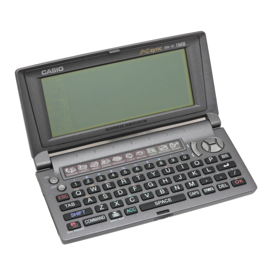
2. GENERAL GUIDE 2-1. Appearances and Display Indicators Display Mode keys Cursor keys Option port AC adaptor connector Keyboard Lock Mini Cradle port P button Battery switch RESET button Option lock switch — 5 —... - Page 6 Display Indicators The following shows the names of the various indicators that appear on the display and explains what they mean. Data runs off the top of the screen. Scroll displayed data by pressing , and . SHIFT: Keyboard is shifted between upper-case and lower-case input. The punctuation marked above the keys in blue can also be input while the keyboard is shifted.
-
Page 7: Modes And Cursor Keys Etc
2-2. Modes and Cursor Keys etc. In order to use the powerful features and functions of the BN Unit, you must first enter one of the following modes. • SCHEDULER • CONTACTS • MEMO • EXPENSE MANAGER • SPREADSHEET • CLOCK •... - Page 8 Using the Cursor Keys Use the large round cursor key located in the upper right corner of the BN Unit’s keyboard whenever you have to perform any operation that requires movement up, down, left, or right. In addition to actually moving the input cursor, the cursor key is also used to select menu bar menus and the commands inside of a menu.
- Page 9 • The contents of this manual are subject to change without notice. • CASIO COMPUTER CO., LTD. assumes no responsibility for any loss or claims by third parties that may arise from the use of this product.
- Page 10 To reset after viewing data 1. After the DATA ERROR message appears, press OK (Yes). 2. In response to the message that appers (DATA ERROR! CONSULT YOUR USER’S GUIDE FOR CORRECT PROCEDURE.), press OK. • This enters the CLOCK Mode. 3.
- Page 11 Memory Status You can use the following procedure at any time to check the current status of BN Unit memory. To check memory status 1. Press MENU BAR to display the menu bar. 2. Use to highlight SYSTEM, and then press 3.
- Page 12 You can press ESC at any time to stop the memory management procedure. Storage Capacity The 2-Mbyte memory capacity of the BN-20 (1-Mbyte for the BN-10) includes a 1,499,136-byte user area (687,104-byte for the BN-10). The following shows examples of what this means for the storage of data in each mode. SCHEDULER...
-
Page 13: Backlight Operation (Bn-20 Only)
2-3. Backlight Operation (BN-20 only) About the EL backlight (BN-20 only) • The BN-20 is equipped with an EL backlight that allows easy viewing of display contents in a theater, or anywhere else where lighting is dim. • Note, however, that frequent or extended use of the EL backlight shortens battery life. The following shows how backlight use affects battery life under controlled test conditions*. -
Page 14: Power Supply
2-4. Power Supply Your BN Unit can be powered by two AA-size alkaline batteries (LR6(AM3)) or the following optional AC adaptor. Optional AC Adaptor: AD-A70140 AD-A70140D-OP: for U.S.A. and Canada (AC 100 ~ 120 V) AD-A70140G-OP: for Europe except U.K. (AC 200 ~ 240 V) AD-A70140A-OP: for Australia (AC 200 ~ 240 V) Impotant! •... - Page 15 To turn power on and off 1. Press the power on key turn to power on. • If you are using a BN-10 Unit, press ON. • If you are using a BN-20 Unit, press ON/OFF. 2. To turn power off, press the power off key.
-
Page 16: Reset Operation And Battery Replacement
To reset the BN Unit 1. Press the power on key (BN-10: ON, BN-20: ON/OFF) to turn on power. 2. Use a thin, pointed object to press the RESET button on the back of the BN Unit. - Page 17 4. In response to the message that appears, press OK to reset the BN Unit and clear all memory contents, or ESC to abort the reset procedure without doing anything. 5. If you pressed OK in the above step, a second confirmation message appears. Press OK to reset the BN Unit and clear all memory contents, or ESC to abort the reset procedure without doing anything.
-
Page 18: Battery Replacement
3-2. Battery Replacement Important! • Always unplug the AC adaptor from the BN Unit before replacing batteries. • Always make sure the battery switch is the NORMAL OPERATION at all times, except when re- placing batteries. 1. Turn off BN Unit power. 2. - Page 19 7. Slide the battery switch back to the NORMAL OPERATION position. “NORMAL OPERATION” 8. Press the power on key (BN-10: ON, BN-20: ON/OFF) to turn on power. • This causes the contrast adjustment screen to appear. 9. Use the cursor keys to adjust the contrast of the display, and then press OK.
- Page 20 Selecting a Time Zone You can select a Home Time zone for the place where you normally work and live, and a second World Time zone for simultaneous time keeping in two locations on the globe. To select a zone 1.
- Page 21 Setting the Home Time Use the following procedure to set the time and date for your Home Time. The times for all other time zones are calculated based on your Home Time setting. • You can set the date within the range of January 1, 1901 through December 31, 2099. To set your Home Time and date 1.
- Page 22 5. After making the settings you want, press OK to register them. Daylight saving time indicator • Turning on daylight saving time causes the standard time to be advanced by one hour. • Note that daylight saving time cannot be turned on for GMT. To select a data format 1.
- Page 23 2. Input the hour and minutes of the alarm time you want to set. • to move the selection (flashing) between the hour and minutes. 3. If you are using the 12-hour time format, be sure to press the keyboard’s A key to indicate “am” or P key for “pm”.
-
Page 24: Data Communication
• PC sync for Windows cannot be used to send data from your computer to another CASIO Digital Diary model. • See the manual that comes with PC sync for Windows for a list of supported CASIO Digital Diary models, required PC system configuration and cable requirements. -
Page 25: Connecting The Casio Bn Unit To Pc
See the documentation that comes with your computer for details. To connect the Mini Cradle to the CASIO BN Unit 1. Make sure that the power of both the BN Unit and your computer is turned off. - Page 26 3. With the side marked CASIO facing up (so you can see it), plug the Mini Cradle connector straight into the BN Unit port. Important! • Make sure you insert the connector as far as it will go, until you hear it snap securely into place.
-
Page 27: Pc Sync For Windows (Brief Explanation)
4-3. PC sync for Windows (Brief explanation) If you want to known PC LINK Software for BN-10/20 (PC sync for Windows) in detail, refer to the User´s Guide for this software. This software is similar to FA-127/128 regarding to operation, but have some features which don´t exist with FA-127/128. - Page 28 2 Next, press START button on the mini cradle. All data is now transferred to PC. Time for this transfer (BN-10: about 10 minutes/ BN-20: about 20 minutes) is very long compared with the other transfer even if the transfer is performed with 38400 b.p.s..
-
Page 29: Operation Check
5. OPERATION CHECK REMARK: Before entering this check, the reset operation is necessary. Therefore, performing this check, all data saved in the unit will be deleted. Before performing this check, transfer all data saved in BN Unit to a personal com- puter using PC LINK software package (floppy disk- 2 sheets, a mini cradle and a instruction manual for this software- PC sync for Windows). -
Page 30: Operation Check
5-2. Operation Check Three items (5. OPTION CHECK/ 6. CRADLE CHECK/ 7. MODEM CHECK) in these nine test items can not be executed for the following reasons. 5. OPTION CHECK- This check can not be performed now, because data transfer between BN Units don't exist and the jack (3 pin) on Main PC board for this data transfer don't exist also. - Page 31 4 PATTERN-3 Press ESC, then 3 button. The following display appears. FRAME SHIFT CAPS COMMAND SEARCH 5 PATTERN-4 Press ESC, then 4 button. The following display appears. ALL DISPLAY SHIFT CAPS COMMAND SEARCH 6 PATTERN-5 Press ESC, then 5 button. The following display appears. NO DISPLAY 7 DD RAM CHECK Press ESC, then 6 button.
- Page 32 8 CONTRAST Press ESC, then 7 button. The following display appears. According to this display, <Contrast Check> change the contrast value from Touch [ESC] Hard lcon Them Test END 00 to 1F using Cursor keys. Touch [<-] Key Then [DRANK] Doing so, brightness of display Touch [->] Key Then [THIN] ( [LIGHT] ) changes from dark to light, and...
- Page 33 " (CS4)= 1M" indicates that the flash ROM of memory capacity 1M byte is mounted on Main PC board as LSI306. "NC" is displayed in stead of "1M" because this LSI306 is not mounted with BN-10. “XXX44” is not displayed with BN-10 also. "XXX5(4)"- If "OKF5(4)" is displayed, the flash ROM of LSI304(LSI306) is formatted and have no memories.
- Page 34 XXXXXXXX NGF4 BANKXX “(CS4)= NC” is displayed in stead of “(CS4)= 1M” with BN-10. And “NGF4” is not displayed with BN-10 also. 8 FLASH CROSS BIT CHECK F The flash ROM LSI304 (306) is formatted at first, and then the data for this check are written into LSI304 (306).
- Page 35 7 NMI CHECK 8 EL ON CHECK 9 EL OFF CHECK Two items (item 8 and item 9) are not displayed with BN-10 because of no EL back light. 2 BEEP Pressing 1 button, BEEP sound is emitted once in one second.
- Page 36 3 ALARM1 Pressing 2 button, BEEP sound is emitted twice in one second. Then press ESC button to stop ringing. 4 ALARM2 Pressing 3 button, BEEP sound is emitted three times in one second. Then press ESC button to stop ringing. 5 CLOCK Pressing 4 button, the following display appears.
- Page 37 8 NMI CHECK The term "NMI" means Non Mask-able Interrupt with CPU. Pressing 7 button, the following display appears. PLEASE NMI Press RESET button on the back of BN Unit using a thin, pointed object. The following display appears. RESET KEY If the AC adapter(AD-A70140) is inserted into the jack, and its output voltage is less than DC 4.4V the following display appears.
-
Page 38: Error Messages
6. ERROR MESSAGES Message Cause Action THAT ALARM TIME IS AL- The time you are trying to set for This is merely a warning mes- READY PASSED! an alarm is already passed. sage that appears for about one second. After that, the dia- log box closes and the data is stored without the alarm. - Page 39 Message Cause Action MEMORY IS FULL! You are trying to input data while First try performing the memory memory is already full. management operation to see if more memory can be made available. If this message still appears, it means that memory is really full.
-
Page 40: Troubleshooting
Power suddenly turns off or Battery power is low. Replace batteries (page 18). contrast adjustment screen • If any of the above does not re- suddenly appears. store your BN Unit to normal operation, contact your nearest CASIO dealer for servicing. — 40 —... -
Page 41: Lsi Pin Function
Non maskable interrupt signal from Gate array (LSI2) to CPU PORT8 Display ON/OFF signal from CPU to LCD driver LSI PORT7 Signal to CPU for selection of BN Units (BN-10: no EL) PORT6 Signal to CPU for control of external port for MODEM PORT5... -
Page 42: Gate Array
8-2. Gate Array (LSI2) Gate array: FM3416 Pin No. Name I / O Function VDD1 Power supply to Gate array (5 V) V5WEB not used V5A20 not used BSYB not used V5A21 not used V5A16 Address bus to ROM for MODEM V5A22 not used V5A15... - Page 43 Pin No. Name I / O Function not used TXD3 not used RXD3 not used Terminal for serial data transfer (both PC LINK and MODEM) Terminal for serial data transfer (both PC LINK and MODEM) VDD1 Power supply to Gate array (5 V) RS (Request signal to PC for sending data) ER (Request signal to PC for operation of PC) Control signal (standby) to line receiver/driver IC (IC501)
-
Page 44: Circuit Explanation
9. CIRCUIT EXPLANATION 9-1. Block Diagram Address bus (BN-20 only) 1 Mbits S-RAM EL driver KEYS (LSI303) DC/AC inverter Buzzer (BN-20 only) 16 Mbits KI/KO 34.5 kHz MASK ROM (LSI301) TX/RX Common- (LSI1) Clock TAB(LSI3) 8 Mbits 319 × 160 dots Clock FLASH ROM 10.14 MHz 32.768 kHz... -
Page 45: Power Supply
9-2. Power Supply Common mode coil (EF601) AC Adapter (7 V) Voltage regulator D606 Q602 V5EXT (5 V) AD-A70140 APO:OFF IC611 (5 V) D605 P5 (from CPU) D607 D601 FUSE (F601) V5SYS D-D Converter (5 V) IC603 (3 V 5 V) BLD2 V2SYS to CPU... -
Page 46: Function
Data transfer speed is 38400 b.p.s. (MAX.) with BN Unit. Data transfer speed of CASIO Digital Diary prior BN Unit is 9600 b.p.s.. So the high speed line receiver/ driver IC (IC501) is necessary with BN Unit. - Page 47 9-3-3. Bias voltage generator IC (IC708) for LCD LCD is driven by steps shaped AC voltage as shown to the right. The number of steps shown to the right is three. This is called 1/3 bias. Generally, if the quantity of pixels in a LCD common line is N dots, the quantity of bias is 1/ N .
-
Page 48: Schematic Diagrams
10. SCHEMATIC DIAGRAMS Main block (PCB ASSY-A140806)-1/5 X1:Ceramic oscillator for Main system clock (10.14 MHz) *BN-10:Z456 X2:Crystal oscillator for Timer clock (32.768 KHz) BN-20:Z457 Connection terminal with soldering-P101, P102 Unit P101 P102 BN-10 no connection with soldering connected with soldering... - Page 49 Main block (PCB ASSY-A140806)-2/5 FM3416 Gate array — 49 —...
- Page 50 Main block (PCB ASSY-A140806)-3/5 1 KEY81 (CHECK/TRANS KEY) is a key for TEST, not one for users. — 50 —...
- Page 51 Main block (PCB ASSY-A140806)-4/5 LINE DRIVER/RECEIVER — 51 —...
- Page 52 Main block (PCB ASSY-A140806)-5/5 AC Adapter — 52 —...
- Page 53 At first FLASH ROM will be used, then MASK ROM will be used. Unit's Name LSI304 LSI306 R335 R336 BN-10 used not used not used not used BN-20 used used used not used — 53 —...
- Page 54 1/16 used used not used not used used This circuit (EL and EL driver) is used only with BN-20, is not used with BN-10. Bias voltage controller for LCD driver R718 R715 C724 C725 — 54 —...
- Page 55 Display block (LCD ASSY-A140809/A140814)-2/3 LCD common terminal driver — 55 —...
- Page 56 Display block (LCD PCB ASSY-A140809/A140814)-3/3 LCD segment terminal driver — 56 —...
- Page 57 Cradle (A140805) shielded BN-10/20 (PCB-Z456-1) — 57 —...
-
Page 58: Disassembly
11. DISASSEMBLY * Refer to 13. EXPLODED VIEW (the parts ( ) are used for only BN-20). 11-1. Disassembly for keyboard side 1. Slide the battery switch on the back of the BN Unit to the REPLACE BATTERIES position. 2. Remove the battery cover 3. -
Page 59: Disassembly For Display Side
11-2. Disassembly for display side 1. Perform the items 1 ~ 9 and 17 of Disassembly of keyboard side . 2. Remove two screws S5 . 3. Remove the lower case using a opener as shown bellow. <Display and upper case side> Blade of opener <Lower case side>... -
Page 60: Parts List
2254 0568 FET 2SK1657-T1B Common Q624 2254 0308 FET 2SJ185-T1B Common LCD ASSY (A140809*1) 6420 8700 PCB ASSY A140817D*1 BN-10 6420 8980 HEAT SEAL A341710-1 BN-10 6420 8990 HEAT SEAL A341711-1 BN-10 6420 9080 LSI/TAB A341911*1 BN-10 6420 9090 LSI/TAB... - Page 61 BN-20 6421 5640 TAPE/SHIELD A443123-1 BN-20 UPPER CASE A ASSY (A140807) 6420 8820 CASE/UPPER A140726-1 Commom 6420 8830 CASE/LOWER A140728-1 BN-10 6420 9440 CASE/LOWER A140728-2 BN-20 6420 8850 FRAME/INNER CASE A140732-1 Common 6420 8680 LCD ASSY A140809A*1 BN-10 6420 9360 LCD ASSY...
- Page 62 Item Code No. Parts Name Specification Applicable TOTAL ASSY 6420 8840 CASE/LOWER BN-10 A140729-1 6420 9480 CASE/LOWER A140729-2 BN-20 6420 8860 FRAME/INNER CASE A140733-1 Common 6420 8920 COVER/BATTERY A241026-1 Common 6420 8950 BUTTON A241029-1 Common 6420 8960 PLATE/CONTACT A241030-1 Common...
-
Page 63: Exploded View
13. EXPLODED VIEW (1/2) WIR1 *Refer to KEY ARRANGEMENT of EXPLODED VIEW (2/2) J601 WIR4 *Refer to CROSS SECTON of CN302 WIR3 EXPLODED VIEW (2/2) CN301 WIR2 — 63 —... - Page 64 ON/OFF LIGHT ESC Q P BS SHIFT DEL OK SPACE CAPS SYMBOL COMMAND BN-10: ON/OFF ON, No light mark, LIGHT OFF CROSS SECTION of LCD ASSY <segment side> <common side> HEAT SEAL ADHESIVE TAPE ADHESIVE TAPE LCD(COMMON) LCD(SEGMENT) PCB ASSY...
- Page 65 CASIO TECHNO CO.,LTD. Overseas Service Division 8-11-10, Nishi-Shinjuku Shinjuku-ku, Tokyo 160-0023, Japan...