Table of Contents
Advertisement
Quick Links
Advertisement
Chapters
Table of Contents
Troubleshooting

Related Manuals for Cisco Catalyst 4500e Series


Summary of Contents for Cisco Catalyst 4500e Series
- Page 1 Catalyst 4500 E-Series Switches Installation Guide November 2007 Americas Headquarters Cisco Systems, Inc. 170 West Tasman Drive San Jose, CA 95134-1706 http://www.cisco.com Tel: 408 526-4000 800 553-NETS (6387) Fax: 408 527-0883 Text Part Number: OL-13972-01...
- Page 2 OR ITS SUPPLIERS HAVE BEEN ADVISED OF THE POSSIBILITY OF SUCH DAMAGES. CCVP, the Cisco logo, and Welcome to the Human Network are trademarks of Cisco Systems, Inc.; Changing the Way We Work, Live, Play, and Learn is a service mark of Cisco Systems, Inc.;...
-
Page 3: Table Of Contents
C O N T E N T S Preface Audience Organization Related Documentation viii Conventions viii Obtaining Documentation and Submitting a Service Request Product Overview C H A P T E R Switch Features Power Redundancy Catalyst 4503-E Switch Features Catalyst 4506-E Switch Features Supervisor Engine Redundancy Catalyst 4507R-E Switch Features... - Page 4 Contents Management Flow 1-35 Switching Traffic Flow 1-36 Preparing for Installation C H A P T E R Electrostatic Discharge Preventing Electrostatic Discharge Damage Site Power Requirements and Heat Dissipation Power Connection Guidelines for AC-Powered Systems Power Connection Guidelines for DC-Powered Systems Calculating DC Input Current Ventilation 2-10...
- Page 5 Contents Verifying the Installation 4-15 Replacing Backplane Modules 4-15 Verify the New Modules 4-18 Supervisor Memory Upgrade 4-19 Tools and Equipment Needed 4-19 Removing Memory 4-19 Installing SDRAM MiniDIMMs 4-21 Troubleshooting C H A P T E R System Boot Verification Using LEDs to Identify Startup Problems System Messages Troubleshooting with Software...
- Page 6 Contents Boot Problems 5-17 Contacting the Cisco Technical Assistance Center 5-18 Serial Numbers 5-19 Specifications A P P E N D I X Catalyst 4503-E Switch Specifications Catalyst 4506-E Switch Specifications Catalyst 4507R-E Switch Specifications Catalyst 4510R-E Switch Specifications Catalyst 4500 Power Supplies...
-
Page 7: Preface
Preface Thi s pr ef ace descr i bes t he audi ence, or gani zat i on, and convent i ons of t he Cat al yst 4500 E- Seri es Swi t ches I nst al l at i on G ui de and pr ovi des i nf or m at i on on how t o obt ai n r el at ed docum ent at i on and t echni cal assi st ance. -
Page 8: Related Documentation
Ref er t o t he f ol l ow i ng docum ent s f or addi t i onal Cat al yst 4500 ser i es and Cat al yst 4500 E- ser i es i nf or m at i on: Catalyst 4500 Series Module Installation Guide at • http://www.cisco.com/en/US/docs/switches/lan/catalyst4500/hardware/module/guide/ mod_inst.html for information about individual switching modules and supervisors not discussed in this publication. - Page 9 Preface Conventions Convention Description { x | y | z } A l t er nat i ve keyw or ds ar e gr ouped i n br aces and separ at ed by ver t i cal bar s. [ x | y | z ] O pt i onal al t er nat i ve keyw or ds ar e gr ouped i n br acket s and separ at ed by ver t i cal bar s.
- Page 10 Preface Conventions Warnings use the following conventions: Warning IMPORTANT SAFETY INSTRUCTIONS This warning symbol means danger. You are in a situation that could cause bodily injury. Before you work on any equipment, be aware of the hazards involved with electrical circuitry and be familiar with standard practices for preventing accidents.
- Page 11 Preface Conventions Avvertenza IMPORTANTI ISTRUZIONI SULLA SICUREZZA Questo simbolo di avvertenza indica un pericolo. La situazione potrebbe causare infortuni alle persone. Prima di intervenire su qualsiasi apparecchiatura, occorre essere al corrente dei pericoli relativi ai circuiti elettrici e conoscere le procedure standard per la prevenzione di incidenti. Utilizzare il numero di istruzione presente alla fine di ciascuna avvertenza per individuare le traduzioni delle avvertenze riportate in questo documento.
- Page 12 Preface Conventions Catalyst 4500 E-Series Switches Installation Guide OL-13972-01...
- Page 13 Preface Conventions Aviso INSTRUÇÕES IMPORTANTES DE SEGURANÇA Este símbolo de aviso significa perigo. Você se encontra em uma situação em que há risco de lesões corporais. Antes de trabalhar com qualquer equipamento, esteja ciente dos riscos que envolvem os circuitos elétricos e familiarize-se com as práticas padrão de prevenção de acidentes. Use o número da declaração fornecido ao final de cada aviso para localizar sua tradução nos avisos de segurança traduzidos que acompanham o dispositivo.
- Page 14 Preface Conventions Catalyst 4500 E-Series Switches Installation Guide OL-13972-01...
-
Page 15: Obtaining Documentation And Submitting A Service Request
Obtaining Documentation and Submitting a Service Request For information on obtaining documentation, submitting a service request, and gathering additional information, see the monthly What’s New in Cisco Product Documentation, which also lists all new and revised Cisco technical documentation, at: http://www.cisco.com/en/US/docs/general/whatsnew/whatsnew.html... - Page 16 Preface Obtaining Documentation and Submitting a Service Request Catalyst 4500 E-Series Switches Installation Guide OL-13972-01...
-
Page 17: Power Redundancy
C H A P T E R Product Overview This chapter provides an overview of the features and components of the Catalyst 4500 E-series switches. The Catalyst 4500 E-series switches are the Catalyst 4503-E switch, the Catalyst 4506-E switch, the Catalyst 4507R-E switch, and the Catalyst 4510R-E switch. The information is presented in these major sections: Switch Features, page 1-1 •... -
Page 18: Product Overview
Chapter 1 Product Overview Switch Features A more detailed discussion of power redundancy is in the Environmental Monitoring and Power Management chapter of the software configuration guide. Refer to the appropriate guide for your software release. Catalyst 4503-E Switch Features The Catalyst 4503-E switch (see Figure 1-1) is a three-slot switch designed for high-performance... -
Page 19: Chapter 1 Product Overview
Chapter 1 Product Overview Switch Features Table 1-1 describes the features of the Catalyst 4503-E switch. Table 1-1 Features of the Catalyst 4503 Switch Feature Description Ethernet speeds • Ethernet (10BASE-T) interface to workstations and repeaters • Fast Ethernet (100BASE-T) interface to workstations, servers, switches, and routers Note Autonegotiation of link speed on each 10/100 port allows migration to... - Page 20 Chapter 1 Product Overview Switch Features Table 1-1 Features of the Catalyst 4503 Switch (continued) Feature Description Switching module 48-port 100BASE-X Fast Ethernet switching module • support (continued) (WS-X4248-FE-SFP) 24-port IEEE 802.3af-compliant PoE 10/100BASE-TX switching module • (WS-X4224-RJ45V) 48-port IEEE 802.3af compliant PoE 10/100BASE-TX RJ-45 switching •...
-
Page 21: Catalyst 4506-E Switch Features
Chapter 1 Product Overview Switch Features Catalyst 4506-E Switch Features The Catalyst 4506-E switch (see Figure 1-2) is a six-slot switch designed for high-performance high-density wiring closet applications. Figure 1-2 Catalyst 4506-E Switch (Front View) 45 06 Fan assembly Supervisor engine (Slot 1) Switching modules (Slots 2 to 6) Power supplies The Catalyst 4506-E switch supports the Supervisor Engine II+, Supervisor Engine II+10GE, Supervisor... - Page 22 Chapter 1 Product Overview Switch Features Table 1-2 describes the features of the Catalyst 4506-E switch. Table 1-2 Features of the Catalyst 4506-E Switch Feature Description Ethernet speeds • Ethernet (10BASE-T) interface to workstations and repeaters • Fast Ethernet (100BASE-T) interface to workstations, servers, switches, and routers Note Autonegotiation of link speed on each 10/100 port allows migration...
- Page 23 Chapter 1 Product Overview Switch Features Table 1-2 Features of the Catalyst 4506-E Switch (continued) Feature Description Switching module 48-port 10/100-Mbps Fast Ethernet switching module • support (continued) (WS-X4148-RJ21) 24-port IEEE 802.3af-compliant PoE 10/100BASE-TX switching • module (WS-X4224-RJ45V) 48-port IEEE 802.3af compliant PoE 10/100BASE-TX RJ-45 switching •...
-
Page 24: Supervisor Engine Redundancy
Redundancy requires that both supervisor engines in the chassis are of the same supervisor engine model, and that they use the same Cisco IOS software image. For more detail about redundancy, refer to the Configuring Supervisor Engine Redundancy Using RPR and SSO chapter of the software configuration guide for your software release. -
Page 25: Catalyst 4507R-E Switch Features
Chapter 1 Product Overview Switch Features Catalyst 4507R-E Switch Features The Catalyst 4507R-E switch (see Figure 1-3) is a seven-slot switch designed for high-performance high-density wiring closet applications. Figure 1-3 Catalyst 4507R-E Switch (Front View) 45 06 Fan Tray Supervisor engines (primary in slot 3, secondary in slot 4) Switching modules (slots 1, 2, 5, 6, 7) Power supplies... - Page 26 Chapter 1 Product Overview Switch Features Table 1-3 describes the features of the Catalyst 4507R-E switch. Table 1-3 Features of the Catalyst 4507R-E Switch Feature Description Ethernet speeds • Ethernet (10BASE-T) interface to workstations and repeaters • Fast Ethernet (100BASE-T) interface to workstations, servers, switches, and routers Note Autonegotiation of link speed on each 10/100 port allows migration to...
- Page 27 Chapter 1 Product Overview Switch Features Table 1-3 Features of the Catalyst 4507R-E Switch (continued) Feature Description Switching module 32-port 10/100-Mbps Fast Ethernet plus 2-port Gigabit Ethernet switching • support module (WS-X4232-GB-RJ) 32-port 10/100-Mbps Fast Ethernet plus 2-port 1000BASE-X Layer 3 •...
- Page 28 Chapter 1 Product Overview Switch Features Table 1-3 Features of the Catalyst 4507R-E Switch (continued) Feature Description Switching module 24-port IEEE 802.3af-compliant PoE 10/100BASE-TX switching module • support (continued) (WS-X4224-RJ45V) 48-port IEEE 802.3af compliant PoE 10/100BASE-TX RJ-45 switching • module (WS-X4248-RJ45V) 48 port IEEE 802.3af compliant PoE 10/100BASE-TX RJ-21 switching •...
-
Page 29: Catalyst 4510R-E Switch Features
Chapter 1 Product Overview Switch Features Catalyst 4510R-E Switch Features The Catalyst 4510R-E switch (see Figure 1-4) is a ten-slot switch designed for high-performance high-density wiring closet applications. Figure 1-4 Catalyst 4510R-E Switch (Front View) 45 06 STA TUS 10/10 0BAS E-TX ETHE RNET STA TUS... - Page 30 Chapter 1 Product Overview Switch Features for a maximum of 384 ports and 4 uplinks. With a Supervisor Engine 6-E, slots 8 to 10 provide 6 Gbps per slot and all other slots provide 24 Gbps per slot. With a Supervisor Engine V or Supervisor Engine V-10GE, all slots are 6 Gbps and E-series switching modules can not be used.
- Page 31 Chapter 1 Product Overview Switch Features Table 1-4 Features of the Catalyst 4510R-E Switch (continued) Feature Description Switching module 24-port 10/100BASE-TX Fast Ethernet switching module • support (WS-X4124-RJ45) 24-port 100BASE-FX Fast Ethernet switching module (WS-X4124-FX-MT) • 48-port 100BASE-FX Fast Ethernet switching module (WS-X4148-FX-MT) •...
-
Page 32: Supervisor Engines
“Specifications.” 2. 1000W AC and 1300W AC power supplies will fit and function; however, power management is cautioned and only some configurations will have adequate power. Please refer to the Cisco Power Calculator at http://tools.cisco.com/cpc/ before configuring these power supplies. - Page 33 • If you move a supervisor engine from a Catalyst 4500 series chassis to a Catalyst 4500-E chassis it must Note use Cisco IOS Release 12.2(37)SG or later. Refer to the release note for software upgrade procedures if needed: http://www.cisco.com/en/US/products/hw/switches/ps4324/prod_release_note09186a0080758ff3.html...
- Page 34 Chapter 1 Product Overview Supervisor Engines Table 1-5 Supervisor Engine Features (continued) Feature Description Supervisor Engine II-Plus 64 Gbps, 48 Mpps (with Catalyst 4506-E and 4507R-E, or 28-Gbps, 21 Mpps with Catalyst 4503-E) full-duplex Gigabit Ethernet switching engine Supervisor 64 Gbps, 48 Mpps (with Catalyst 4503-E only) full-duplex Gigabit Engine II-Plus TS Ethernet switching engine Supervisor...
- Page 35 Chapter 1 Product Overview Supervisor Engines GBIC uplink ports Compact flash port Switch load indicators Reset button Console port Figure 1-6 Catalyst 4500 Series Supervisor Engine II-Plus TS (WS-X4013+TS) Status LED Management port PoE status LED Compact Flash port Switch load indicators Reset button Console port Figure 1-7...
- Page 36 Chapter 1 Product Overview Supervisor Engines Figure 1-8 Supervisor Engine IV (WS-X4515) Status LED Management port GBIC uplink ports Compact flash port switch load indicators Reset button Console port Figure 1-9 Supervisor Engine V (WS-X4516) Status LED Management port GBIC uplink ports Compact Flash port Switch load indicators Reset button...
- Page 37 Chapter 1 Product Overview Supervisor Engines Figure 1-10 Supervisor Engine V-10GE (WS-X4516-10GE) Compact flash port Gigabit SFP ports Switch load indicator Management port RESET button CONSOLE port 10GE uplink ports STATUS LED Figure 1-11 Supervisor Engine 6-E (WS-X45-Sup6-E) Status LED Uplink ports Reset button USB port...
-
Page 38: Leds
GBICs, refer to the Catalyst 4500 Series Module Installation Guide. Frequently updated compatibility information for GBICs, X2s, and SFPs are in documents at: http://www.cisco.com/en/US/products/hw/modules/ps5455/products_device_support_tables_list.html When two Supervisor Engine Vs are present in a Catalyst 4507R-E and Catalyst 4510R-E, all four uplinks are active on both Primary (active) and Secondary (standby) supervisor engines by default, or two uplinks are active in a non-redundant configuration. -
Page 39: 10-Gigabit Ethernet Uplink Ports
WS-X4516-10GE, and WS-X4013+10GE supervisors, as well as some switching modules. WS-X45-Sup6-E supervisors can use Cisco TwinGig converters to support two SFPs per X2 uplink port, for a maximum of 4 SFP ports per supervisor. SFP connectors vary with interface type and may use multimode fiber (MMF), single-mode fiber (SMF) cable, or copper Ethernet cables. -
Page 40: Reset Button
The Compact Flash slot accepts a Type 1 Compact Flash disk. You can use it for file transfer tasks such as loading a new software image. The Compact Flash card is optional. For more information, refer to Using the Compact Flash on the Catalyst 4500 Supervisor Engines at the following URL: http://www.cisco.com/en/US/docs/switches/lan/catalyst4500/hardware/configuration/notes/ OL_2788.html Fan Assembly... -
Page 41: Power Supplies
Chapter 1 Product Overview Power Supplies Figure 1-12 Catalyst 4506-E Airflow 45 06 Fan assembly Power Supplies For detailed specifications on all Catalyst 4500 power supplies, refer to the “Catalyst 4507R-E Switch Note Specifications” section on page A-3. A Catalyst 4500 E-series switch can use a 1000 W, 1300 W, 1400 W, 2800 W (see Figure 1-13), or 4200 W (with two inputs, see... - Page 42 Chapter 1 Product Overview Power Supplies Figure 1-13 AC-Input Power Supply (All Except 4200 W) AC receptacle Captive screws Power switch Figure 1-14 4200 W Dual Input AC Power Supply 10 0- 12 0V - 12 A 50 /6 0H O UT P{ UT FA FA N O...
- Page 43 Catalyst 4510R-E; however, power management may be required in high density configurations.) Cisco recommends the use of the 1400 W DC, 1400 W AC, and 2800 W AC power supplies for the Catalyst 4510R-E.
-
Page 44: Power Supply Leds
Chapter 1 Product Overview Power Supplies Power Supply LEDs Table 1-7 describes the power supply LEDs. Table 1-7 Power Supply LEDs Color/State Description INPUT OK Indicates whether the input voltage is within the required range: Green Input voltage is within the required range. Flashing Input voltage is present, but is below required range. -
Page 45: Environmental Monitoring Feature
The supervisor engine monitors the status of each power supply and provides a status report through the switch software. For more details on how the supervisor engine monitors the power supplies, refer to the “Environmental Monitoring and Power Management” chapter of the Catalyst 4500 Series Switch Cisco IOS Software Configuration Guide. - Page 46 Chapter 1 Product Overview Power Supplies The maximum total input current is 42.5A and the maximum ambient temperature is 55 C. To determine total maximum input power to a supply, add up the active individual module input power ratings. Table 1-9 provides output information for these modes, given two supplies working in combined mode.
-
Page 47: System Architecture
Chapter 1 Product Overview System Architecture Table 1-11 Minimum Load Table (continued) PSU1 PSU2 3.3V Minimum Minimum Input 1 Input 2 Input 3 Input 1 Input 2 Input 3 Load Load Mode 5 – – – 0.6A Dual Redundant Operation Mode 1 2.66A 1.2A... -
Page 48: Power Flow
Power over Ethernet The Cisco Catalyst 4500 E-series switches support the 802.3af standard for PoE on 10/100 or 10/100/1000 ports, enabling customers to support telephones, wireless base stations, video cameras, and other appliances. PoE makes it possible to place devices in unique locations without having to provide... - Page 49 (UPS) backup. All new Cisco Catalyst PoE switching modules can support 15.4 W of power per port simultaneously. Not only do the modules support the IEEE standard, including the optional power classifications, but the Cisco pre-standard power implementation is also supported to help ensure backward compatibility with existing Cisco powered devices.
- Page 50 (data only), 1300 W (data and PoE), 1400 W DC (data and PoE), 2800 W (data and PoE), and 4200 W AC (data and PoE). When more than 4200 W of redundant data and PoE are required for a Cisco Catalyst 4500 E-series chassis in an AC-powered environment, Cisco offers an external AC power shelf that houses two 2500 W AC power supplies.
-
Page 51: Management Flow
Cisco Catalyst 4503-E with a single 15 A circuit. Likewise, it is possible to deploy a fully populated Cisco Catalyst 4510R-E with two 20 A and one 15 A circuits rather than a single 60 A connection, which often requires rack rewiring. -
Page 52: Switching Traffic Flow
Chapter 1 Product Overview System Architecture Switching Traffic Flow All Catalyst 4500 series switches use a shared memory switching fabric. All forwarding decisions, QoS, security policies and transmit queuing are implemented in the Supervisor Engine. Individual switching modules are transparent, and only contain simple stub ASICs and PHYs; they do not perform buffering or local switching. - Page 53 As a result, business-critical applications such as Voice-over-IP (VoIP) calls are not dropped. The Nonstop Forwarding (NSF) Aware feature in Cisco IOS software is also supported, providing the ability to interface with NSF-capable devices and to continue forwarding packets as routing information is updated upon a supervisor-engine switchover.
- Page 54 Chapter 1 Product Overview System Architecture Catalyst 4500 E-Series Switches Installation Guide 1-38 OL-13972-01...
-
Page 55: Preparing For Installation
C H A P T E R Preparing for Installation Warning This unit is intended for installation in restricted access areas. A restricted access area can be accessed only through the use of a special tool, lock and key, or other means of security. Statement 1017 Warning Only trained and qualified personnel should be allowed to install, replace, or service this equipment. -
Page 56: Chapter 2 Preparing For Installation
Chapter 2 Preparing for Installation Electrostatic Discharge See the Site-Planning Checklist at the end of this chapter to help ensure that you complete all Note site-planning activities before you install the switch. Electrostatic Discharge Electrostatic discharge is common on Category 5E and Category 6 cabling systems. Category 5E and Category 6 cables have higher capacitance than Category 5 cables. -
Page 57: Site Power Requirements And Heat Dissipation
Catalyst 4500 E-series switches. You should verify site power before you install the switch. For more information about power management and planning, refer to the “Environmental Monitoring and Power Management” chapter in the Catalyst 4500 Series Switch Cisco IOS Software Configuration Guide version appropriate for your software. - Page 58 1000 W—Table 2-1 lists the AC-input power cord options, specifications, Cisco part numbers, and shows the different styles of 1000 W AC-input power cord wall plugs that are available for North America and international locations as well as the appliance coupler that is attached to the power supply end of the power cord.
- Page 59 Chapter 2 Preparing for Installation Power Connection Guidelines for AC-Powered Systems Table 2-1 AC-Input Power Cord Options Locale Part Number Length Plug Rating Plug Type Appliance Coupler 1000 W Power Supply (PWR-C45-1000AC=) North America CAB-7KAC= 8.2 ft (2.5 m) 125 VAC, 15 A NEMA 5-15P Australia, CAB-7KACA=...
- Page 60 Chapter 2 Preparing for Installation Power Connection Guidelines for AC-Powered Systems Table 2-1 AC-Input Power Cord Options (continued) Locale Part Number Length Plug Rating Plug Type Australia, CAB-7513ACA= 14 ft (4.3 m) 250 VAC, 15 A SAA/3, New Zealand AS/NZZS 3112-1993 Europe (except CAB-7513ACE= 14 ft (4.3 m) 250 VAC, 16 A...
- Page 61 Chapter 2 Preparing for Installation Power Connection Guidelines for AC-Powered Systems Table 2-1 AC-Input Power Cord Options (continued) Locale Part Number Length Plug Rating Plug Type International CAB-AC-2800W-INT= 13.6 ft 250 VAC, 16 A IEC 309 (4.1 m) Appliance Coupler 2800 W Power Supply (PWR-C45-2800ACV=) North America CAB-AC-2800W-TWLK= 13.6 ft...
- Page 62 Chapter 2 Preparing for Installation Power Connection Guidelines for AC-Powered Systems Table 2-1 AC-Input Power Cord Options (continued) Locale Part Number Length Plug Rating Plug Type North America CAB-US620P-C19-US 13.2 ft 250 VAC, 20 A NEMA 6-20 (non-locking) (4.02 m) non-locking 200–240 VAC operation...
-
Page 63: Power Connection Guidelines For Dc-Powered Systems
Connection to the DC-input power supply requires one earth ground cable, one source DC (–), and one source DC return (+). The length of the cables depends on your switch location. These cables are not available from Cisco Systems. They are available from any commercial cable vendor. -
Page 64: Ventilation
• 10 X 6.3 W = 63 W for inline devices. 6.3 Watts is correct for a Cisco IP phone. Wattage consumption will depend on the inline device used. Find the DC input power using the DC output power. Step 4 63/.96 (efficiency) = 65 W of DC input power. -
Page 65: Calculating System Heat Dissipation
Chapter 2 Preparing for Installation Site-Planning Checklist Calculating System Heat Dissipation To calculate the expected heat dissipation from a switch, add the total amount of power drawn from power supply by the system's configuration, then divide the total amount of power by the efficiency of the power supply. - Page 66 Chapter 2 Preparing for Installation Site-Planning Checklist Table 2-2 Site-Planning Checklist Task No. Planning Activity Verified by Time Date Space evaluation: • Space and layout • Floor covering Impact and vibration • Lighting • Maintenance access • Environmental evaluation: Ambient temperature •...
-
Page 67: Repacking A Switch
C H A P T E R Installing the Switch in a Rack Warning This unit is intended for installation in restricted access areas. A restricted access area can be accessed only through the use of a special tool, lock and key, or other means of security. Statement 1017 Warning Only trained and qualified personnel should be allowed to install, replace, or service this equipment. -
Page 68: Chapter 3 Installing The Switch In A Rack
Chapter 3 Installing the Switch in a Rack Rack-Mounting the Switch Follow these steps to check the contents of the shipping cartons: Check the contents of the accessories box against the Accessories Box Components Checklist and the Step 1 packing slip that were included with your switch. Verify that you received all listed equipment, including the following: Switch hardware documentation and software documentation (if ordered) •... -
Page 69: Rack-Mounting Catalyst 4500 E-Series Switches
If you move a supervisor engine from a Catalyst 4500 series chassis to a Catalyst 4503-E chassis or Catalyst 4506-E chassis, it must use Cisco IOS Release 12.2(37)SG or later. Refer to the release note for software upgrade procedures if needed: http://www.cisco.com/en/US/docs/switches/lan/catalyst4500/release/note/OL_5184.html#wp305142... - Page 70 Chapter 3 Installing the Switch in a Rack Rack-Mounting the Switch Figure 3-1 for the Catalyst 4506-E switch, the other switches will be very similar. Figure 3-1 Attaching the Cable Guide to the Catalyst 4506-E Switch 45 06 Install the chassis in the rack as follows: Step 2 Insert the rear of the chassis between the mounting posts.
-
Page 71: System Ground Connection Guidelines
Chapter 3 Installing the Switch in a Rack System Ground Connection Guidelines Figure 3-2 Installing a Catalyst 4506-E Switch in the Rack 45 06 Make sure that the ejector levers are completely closed and the supervisor engine and switching modules Step 3 are installed securely. -
Page 72: Parts And Required Tools
Installing the Switch in a Rack System Ground Connection Guidelines Parts and Required Tools Some parts and required tools described in this section are not available from Cisco Systems. The Note grounding lug and associated screws are included with the accessory kit. - Page 73 Chapter 3 Installing the Switch in a Rack System Ground Connection Guidelines Figure 3-3 Connecting System Ground on the Switch Grounding wire Grounding pad Screws (M4) Grounding lug Remove the label that covers the grounding pad. Step 5 Place the grounding lug against the grounding pad, aligning the holes. Insert the two M4 screws through Step 6 the holes in the grounding lug and grounding pad.
- Page 74 If you move a supervisor engine from a Catalyst 4500 series chassis to a Catalyst 4503-E chassis or Note Catalyst 4506-E chassis, it must use Cisco IOS Release 12.2(37)SG or later. Refer to the release note for software upgrade procedures if needed: http://www.cisco.com/en/US/docs/switches/lan/catalyst4500/release/note/OL_5184.html#wp305142...
-
Page 75: Removing And Replacing Frus
C H A P T E R Removing and Replacing FRUs Warning Read the installation instructions before connecting the system to the power source. Statement 1004 Warning Only trained and qualified personnel should be allowed to install, replace, or service this equipment. Statement 1030 This equipment must be grounded. -
Page 76: Chapter 4 Removing And Replacing Fru
Chapter 4 Removing and Replacing FRUs Removing and Replacing the Power Supply Removing and Replacing the Power Supply This section describes how to remove and install the AC-input power supply and DC-input power supply for the Catalyst 4500 E-series switches. This information is presented in the following sections: Required Tools, page 4-4 •... - Page 77 Chapter 4 Removing and Replacing FRUs Removing and Replacing the Power Supply Figure 4-2 4200 W Dual-Input AC Power Supply 10 0- 12 0V - 12 A 50 /6 0H O UT P{ UT FA FA N O IN P U T P O E E N A B LE IN P U T...
-
Page 78: Figure
Chapter 4 Removing and Replacing FRUs Removing and Replacing the Power Supply Figure 4-4 1400 W DC Triple-input Power Supply Captive screws Required Tools You will need a flathead or Phillips screwdriver to perform these procedures. Removing an AC-Input Power Supply Follow these steps to remove the AC-input power supply: Press the power switch on the AC-input power supply down to the off (O) position (see Figure... - Page 79 Chapter 4 Removing and Replacing FRUs Removing and Replacing the Power Supply Figure 4-6 Loosening the Side-Clamp Screw Step 3 Disconnect the power cord from the power supply being removed. Step 4 Loosen the two captive screws (see Figure 4-7). Figure 4-7 Loosening the Captive Screws Captive screws...
-
Page 80: Installing An Ac-Input Power Supply
Chapter 4 Removing and Replacing FRUs Removing and Replacing the Power Supply Figure 4-8 Handling an AC-Input Power Supply Step 6 Pull the power supply out of the bay and set it aside. Blank faceplates and cover panels serve three important functions: they prevent exposure to Warning hazardous voltages and currents inside the chassis;... - Page 81 Chapter 4 Removing and Replacing FRUs Removing and Replacing the Power Supply Step 6 Using a screwdriver, tighten the two captive installation screws (see Figure 4-1) on the front panel of the AC-input power supply. Step 7 Make sure the power supply power switch is in the off position (O). Before you connect the power supply to a power source, ensure that all site power and grounding Step 8 requirements have been met.
-
Page 82: Removing A Dc-Input Power Supply
Chapter 4 Removing and Replacing FRUs Removing and Replacing the Power Supply Step 13 Check the power supply and system status from the system console by entering show power command. For more information on this command, refer to the command reference publication for your switch. Step 14 If the LEDs or show power command output indicate a power problem or other system problem, see Chapter 5, “Troubleshooting,”... - Page 83 Chapter 4 Removing and Replacing FRUs Removing and Replacing the Power Supply Figure 4-11 DC-Input Power Supply Main power switch In-line power switch Captive screw Serial communication connector Captive screw Terminal block Figure 4-12 DC Triple-input Power Supply Captive screw Output Fail LED Plus (+) Fan OK LED...
- Page 84 Chapter 4 Removing and Replacing FRUs Removing and Replacing the Power Supply Figure 4-13 Connecting the DC-Input Wires RS-485 serial communnication connector DC-input wires Negative Positive Ground Grounding lug Grounding lug nuts Figure 4-14 Connecting the DC-Input Wires (Triple-input Power Supply) DC-input wires Negative Positive...
-
Page 85: Installing A Dc-Input Power Supply
Chapter 4 Removing and Replacing FRUs Removing and Replacing the Power Supply Step 7 Grasp the power supply handle with one hand. Place your other hand underneath as you slowly pull the power supply out of the bay (see Figure 4-16). -
Page 86: Installation Procedure
Chapter 4 Removing and Replacing FRUs Removing and Replacing the Power Supply Installation Procedure Warning Before performing any of the following procedures, ensure that power is removed from the DC circuit. Statement 1003 Warning A readily accessible two-poled disconnect device must be incorporated in the fixed wiring. Statement 1022 This product requires short-circuit (overcurrent) protection, to be provided as part of the building Warning... -
Page 87: Removing And Replacing The Chassis Fan Assembly
For more information on the commands, refer to the command reference publication for your switch and software. If the LEDs or the show power command (Cisco IOS) output indicate a power problem or other system Step 10 problem, see Chapter 5, “Troubleshooting,”... -
Page 88: Installing The Fan Assembly
Chapter 4 Removing and Replacing FRUs Removing and Replacing the Chassis Fan Assembly Figure 4-17 Catalyst 4506-E System Fan Assembly 45 06 Captive installation screws Fan assembly Grasp the fan assembly with both hands and pull it outward; gently move it side to side if necessary to Step 2 unseat it from the backplane. -
Page 89: Verifying The Installation
If after several attempts the fans do not operate, or if you experience trouble with the installation (for Step 3 instance, if the captive installation screws do not align with the chassis holes), contact the Cisco TAC for assistance. Replacing Backplane Modules There are 5 redundancy modules (also called mux buffers) and 1 clock module on a Catalyst 4507R-E chassis backplane. - Page 90 Chapter 4 Removing and Replacing FRUs Replacing Backplane Modules Figure 4-18 Catalyst 4507R-E Backplane Clock module Mux buffers If you are removing a clock module, remove the two screws that attach the module to the backplane. Step 4 Find the seating levers on both sides of the connector for the module you wish to replace. (See Step 5 Figure 4-19.)
- Page 91 Chapter 4 Removing and Replacing FRUs Replacing Backplane Modules Figure 4-20 Releasing the Module Pull out the module while holding the top left and top right corners. (See Figure 4-21.) Step 7 When handling the modules, do not touch the chips or the gold edge contacts on the module. Note Figure 4-21 Removing the Module...
-
Page 92: Verify The New Modules
Chapter 4 Removing and Replacing FRUs Replacing Backplane Modules Figure 4-23 Correct Module Seating Good Push the module toward the back of the chassis and make sure it is clipped in by the levers on both sides. Step 10 (See Figure 4-24.) Figure 4-24... -
Page 93: Supervisor Memory Upgrade
This section describes how to perform a memory upgrade. You might need to upgrade memory on the Supervisor Engine 6-E for the following reasons: To upgrade to a new Cisco IOS feature set or release that requires additional memory. (Memory •... - Page 94 Chapter 4 Removing and Replacing FRUs Supervisor Memory Upgrade Figure 4-25 Catalyst 4500 E-Series Supervisor Engine 6-E (WS-Sup-6-E) Lower slot (u50) Upper slot (u39) Additional memory to be installed in this slot base memory is already installed Caution Handle the miniDIMM by the edges only; do not touch the memory modules, pins, or traces (metal fingers along the connector edge).
-
Page 95: Installing Sdram Minidimms
Chapter 4 Removing and Replacing FRUs Supervisor Memory Upgrade Figure 4-26 Removing and Installing SDRAM MiniDIMMs Pull the tabs away with your thumbs, bracing your forefingers against the rails. The memory module will pop loose. Then raise the memory module to a vertical position. - Page 96 Chapter 4 Removing and Replacing FRUs Supervisor Memory Upgrade Step 3 Hold the miniDIMM component-side up, with connector edge (the metal fingers) away from you. Keep the sides of the miniDIMM between your thumb and middle finger, with your forefinger against the far edge and opposite the connector edge.
-
Page 97: Troubleshooting
Information specific to your software release can be found in the software configuration guide for that release, or in the system message guide for your release. The following links may be useful in combination with this chapter: Release notes • http://www.cisco.com/en/US/products/hw/switches/ps4324/prod_release_notes_list.html Error Message Decoder • http://www.cisco.com/cgi-bin/Support/Errordecoder/index.cgi •... -
Page 98: Chapter 5 Troubleshooting
1 stop bit. Watch for any system messages after startup. That the power supplies are supplying power to the system • The power supply’s LEDs should be green. Use the show environment Cisco IOS command to view power supply activity. That the system fan assembly is operating •... - Page 99 For more information, see the “Troubleshooting Switching Modules” section on page 5-8. If you determine that the switching module is not operating, contact Cisco TAC as described in the “Some Problems and Solutions” section on page 5-14.
-
Page 100: System Messages
Most messages are also documented in the Error Message Decoder tool at: http://www.cisco.com/cgi-bin/Support/Errordecoder/index.cgi System messages specific to the system components are mentioned in the corresponding sections that follow. -
Page 101: System Messages And Power Problems
Step 9 If you are unable to resolve the problem, or if you determine that either a power supply or backplane connector is faulty, contact Cisco Technical support for instructions. System Messages and Power Problems Check for system messages related to the power supply, and refer to the system message guide for your software release. -
Page 102: Power Supply Mixing
Verify that all fans are operating. You should hear the fans at system start. Step 7 If the system is still detecting a fan assembly failure, check for details using the CLI and contact the Step 8 Cisco TAC for assistance. Catalyst 4500 E-Series Switches Installation Guide OL-13972-01... -
Page 103: System Messages And Fan Problems
Troubleshooting Backplane Modules The Cisco Catalyst 4500 E-series redundancy scheme uses removable redundancy modules (also called mux-buffers), on the passive backplane to switch traffic to the active supervisor engine. There is one redundancy module per switching module. Redundancy modules and a redundant clock ship standard with every Cisco Catalyst 4507R-E and 4510R-E chassis. -
Page 104: Troubleshooting Switching Modules
Chapter 5 Troubleshooting Troubleshooting Switching Modules If you observe these conditions, contact the Cisco TAC for assistance in ordering replacement redundancy modules and a clock. Troubleshooting Switching Modules Each switching module has one LED labeled STATUS that provides information about the module and one numbered LED labeled LINK for each port on the module. -
Page 105: System Messages And Switching Modules
If you see any of these messages or other messages, go to the following location and enter the message text to find recommendations for your situation. http://www.cisco.com/cgi-bin/Support/Errordecoder/index.cgi Useful CLI Commands Some problems can be solved by resetting the switching module. Use the hw-module module <n> reset command to reset a switching module, or remove and re-insert the switching module, which resets, restarts, and power cycles the switching module. -
Page 106: Troubleshooting Supervisor Engines
Chapter 5 Troubleshooting Troubleshooting Supervisor Engines Troubleshooting Supervisor Engines This section only addresses problems with hardware. Problems with features or configuration are not covered here. Refer for your software configuration guide and release notes for information on configuring features or identifying known problems. Table 5-2 describes the supervisor engine LEDs. - Page 107 These system messages indicate a problem with the supervisor engine. Some problems will prevent a console connection and will not allow you to use messages in diagnosing a problem. If you are unable to establish a terminal connection and the STATUS LED is red, contact Cisco TAC immediately to order a replacement.
-
Page 108: Useful Cli Commands
LED, create a console connection to the standby supervisor engine and verify that it is in ROMmon mode or in continuous reboot. If the standby supervisor engine is in either of these two states, refer to: http://www.cisco.com/en/US/products/hw/switches/ps663/products_configuration_example09186a008 0094ecf.shtml switch# show module... -
Page 109: Switch Self-Reset
Use the procedure in the software configuration guide for your release. If the standby supervisor engine still does not come on line, create a service request with Cisco Technical Support. Use the log of the switch output that you collected from the previous troubleshooting steps. -
Page 110: Some Problems And Solutions
If you troubleshoot these common reasons and you are not able to narrow down the problem, follow the steps in this section and capture the output of commands at each step, then contact Cisco Technical Support for additional troubleshooting assistance. -
Page 111: Interface Problems
EtherChannel, trunking, or an autonegotiation delay causes. For more information about these delays and possible solutions, refer to http://www.cisco.com/en/US/products/hw/switches/ps700/products_tech_note09186a00800b1500.sht If you review and follow the procedure in the document and you still have issues, contact Cisco Technical Support. Catalyst 4500 E-Series Switches Installation Guide... -
Page 112: Nic Compatibility Issues
For more troubleshooting information, refer to: http://www.cisco.com/en/US/products/hw/switches/ps700/products_tech_note09186a00800a7af0.shtm If you still have issues after you review and follow the procedure in the document Troubleshooting Cisco Catalyst Switches to NIC Compatibility Issues, contact Cisco Technical Support for further assistance. -
Page 113: Boot Problems
“Recovering from a Continuous Reboot” section of the document at this location: http://www.cisco.com/en/US/products/hw/switches/ps663/products_configuration_example09186a008 0094ecf.shtml The supervisor engine goes into ROMmon mode or fails to boot when the system image is either corrupt or absent. -
Page 114: Contacting The Cisco Technical Assistance Center
If you are unable to solve a startup problem after using the troubleshooting suggestions in this chapter, contact a Cisco TAC representative for assistance and further instructions. Before you call, have the following information ready to help the Cisco TAC assist you as quickly as possible: Date you received the switch •... -
Page 115: Serial Numbers
Chapter 5 Troubleshooting Contacting the Cisco Technical Assistance Center • Maintenance agreement or warranty information Brief description of the problem • Console captures related to your problem • Brief explanation of the steps you have already taken to isolate and resolve the problem •... - Page 116 Chapter 5 Troubleshooting Contacting the Cisco Technical Assistance Center Catalyst 4500 E-Series Switches Installation Guide 5-20 OL-13972-01...
-
Page 117: Catalyst 4503-E Switch Specifications
Specifications for individual switching modules and supervisor engines, including power consumption Note and thermal output information, are in the Catalyst 4500 Series Module Installation Guide, available online at: http://www.cisco.com/en/US/docs/switches/lan/catalyst4500/hardware/module/guide/mod_inst.html Catalyst 4503-E Switch Specifications Table A-1 lists the Catalyst 4503-E switch specifications. -
Page 118: Specifications
Appendix A Specifications Catalyst 4506-E Switch Specifications Table A-1 Catalyst 4503-E Switch Specifications (continued) Item Specification Switching Components Backplane 24 Gbps full duplex backplane Port density 116 10/100/1000 ports when using a Catalyst 4500 Series Supervisor Engine II-Plus TS, 96 10/100/1000 ports with other supervisor engines, or 12 10-Gbps X2 ports Two 10-Gbps Uplinks, and up to 12 10-Gbps ports on switching module slots... -
Page 119: Catalyst 4507R-E Switch Specifications
Appendix A Specifications Catalyst 4507R-E Switch Specifications Table A-2 Catalyst 4506-E Switch Specifications (continued) Item Specification Altitude: operating and nonoperating –196 to 6561 ft (–60 to 2000 m) Switching Components Backplane 120 Gbps full duplex Port density 240 (max) 10/100/1000 ports Two 10-Gbps Uplinks, and up to 30 10-Gbps ports on switching module slots Inline power... - Page 120 Appendix A Specifications Catalyst 4507R-E Switch Specifications Table A-3 Catalyst 4507R-E Switch Specifications (continued) Item Specification Altitude: operating –196 to 6561 ft (–60 to 2000 m) nonoperating –1000 to 30,000 ft (–300 to 9150 m) Switching Components Backplane 120 Gbps full duplex 4 Gbps Uplinks with Sup II+, Sup IV, and Sup 6-E with TwinGig converters 8 Gbps Uplinks with Supervisor Engine V...
-
Page 121: Catalyst 4510R-E Switch Specifications
Appendix A Specifications Catalyst 4510R-E Switch Specifications Catalyst 4510R-E Switch Specifications Table A-4 lists the Catalyst 4510R-E switch specifications. Table A-4 Catalyst 4510R-E Switch Specifications Item Specification Environmental Temperature, ambient operating 32 to 104°F (0 to 40°C) ambient nonoperating and storage –40 to 167°F (–40 to 75°C) Humidity (RH), ambient (noncondensing): operating... -
Page 122: Catalyst 4500 Power Supplies
International locations. For more information about power management and planning, refer to the “Environmental Monitoring and Power Management” chapter in the Catalyst 4500 Series Switch Cisco IOS Software Configuration Guide version appropriate for your software. Catalyst 4500 E-Series Switches Installation Guide... - Page 123 Specification Minimum software requirement Cisco IOS Release 12.1(12c)EW Power over Ethernet Supported, up to 800 W (211 Cisco phones in combined mode) AC-input type Autoranging input with power factor corrector AC-input voltage 100 to 240 VAC (±10% for full range)
- Page 124 DC-input current Data only: 31 A @ –60 VDC Data and inline devices: 180 A maximum @ –48 VDC input The input power is configurable in the CLI. The Cisco Note IOS command is power dc input. Configure the switch software to match the requirements of your switch.
- Page 125 Appendix A Specifications Catalyst 4500 Power Supplies Table A-8 1400 W DC-Input Power Supply Specifications (continued) Item Specification Input power 1866 W (Data only) Current draw At –40.5 V (min voltage) 46 A Current draw at –72 V (max voltage) 25.9 A Max heat dissipation at 1866 W 5760 BTUs...
- Page 126 4910 BTUs Table A-9 1400 W DC Triple-Input Power Supply Specifications Item Specification Minimum software requirement Cisco IOS Release 12.2(25)EW Power over Ethernet Not supported DC-input voltage Domestic and international: –48 to –60 VDC DC-input current 42.5 A maximum @ –48 VDC input Input 1: 12.5 A at –48 to –60 VDC...
- Page 127 Appendix A Specifications Catalyst 4500 Power Supplies Table A-9 1400 W DC Triple-Input Power Supply Specifications (continued) Item Specification Catalyst 4503-E Specific Power Usage Two modules minimum required @ –40.5 VDC input (data only) One 15A module minimum required @ –44 VDC input Maximum draw 475 W Maximum input...
- Page 128 Specification Minimum software requirement Cisco IOS Release 12.1(13)EW Power over Ethernet Supported, up to 1400 W (240 Cisco phones in combined mode) AC-input type Autoranging input with power factor corrector AC-input voltage 200 to 240 VAC (±10% for full range)
-
Page 129: Table
Appendix A Specifications Catalyst 4500 Power Supplies Table A-13 4200 W AC-Input Power Supply Specifications Item Specification Maximum KVA rating 5.25 KVA Power supply output 4200 W maximum @ 230 VAC 12 V @ 115.3 A, 3.3 V @12.5 A (Data) –50 V @ 77.1 A (PoE) with two inputs 2100 W maximum @ 230 VAC 12 V @115.3 A, 3.3 V @12.5 A (Data) - Page 130 Appendix A Specifications Catalyst 4500 Power Supplies Table A-15 Combined Mode Output 12 V 3.3 V -50 V Total Both sides at 220 1360 4700 5493 Both sides at 220+220 1360 6800 7600 Table A-16 AC and DC Power Information and Heat Dissipation Specifications AC or Input Input...
-
Page 131: Repacking A Switch
A P P E N D I X Repacking a Switch If you need to return your Catalyst 4500 E-series switch to the factory, use the instructions in this appendix to repack your switch in preparation for shipping. To repack the switch using the original packaging material, follow these steps: Slide the pieces of the packing foam over the Catalyst 4500 E-series switch. - Page 132 Appendix B Repacking a Switch Figure B-1 Catalyst 4500 E-series Switch Packing Material Documentation and accessories Packing foam Packing carton Packing foam Packing foam Catalyst 4500 E-Series Switches Installation Guide OL-13972-01...
-
Page 133: Initial Configuration For The Switch
If you move a supervisor engine from a Catalyst 4500 series chassis to a Catalyst 4503-E chassis or Catalyst 4506-E chassis, it must use Cisco IOS Release 12.2(37)SG or later. Refer to the release note for software upgrade procedures if needed: http://www.cisco.com/en/US/docs/switches/lan/catalyst4500/release/note/OL_5184.html#wp305142... -
Page 134: Connecting To The Switch
Appendix C Initial Configuration for the Switch Connecting to the Switch Connecting to the Switch You must use the console port to perform the initial configuration. To connect the switch console port to a PC, use the supplied RJ-45-to-DB-9 adapter cable. Follow these steps to connect the PC or terminal to the switch: Using the supplied RJ-45-to-DB-9 adapter cable, insert the RJ-45 connector into the console port that is Step 1... -
Page 135: Entering The Initial Configuration Information
POST lasts approximately 1 minute. After POST is complete, the system and status LEDs remain green. If the switch fails POST, the system LED turns amber. POST failures are usually fatal. Call Cisco Systems if your switch does not pass POST. Note If you started the terminal-emulation program before you powered on your switch, the PC or terminal displays the bootloader sequence. - Page 136 Appendix C Initial Configuration for the Switch Entering the Initial Configuration Information Step 4 Enter the configure terminal command to enter global configuration mode. Switch# configure terminal Enter configuration commands, one per line. End with CNTL/Z. Switch (config)# Configure the system prompt and host name for the switch, and press Return. To remove the new prompt Step 5 and return the prompt to its default, use the no hostname command.
- Page 137 Appendix C Initial Configuration for the Switch Entering the Initial Configuration Information !--- Output suppressed. Configure a default route: Step 13 Switch1(config)#ip route 0.0.0.0 0.0.0.0 172.16.1.1 Verify the IP information by using the show ip interface brief and show ip route commands. Step 14 Switch1# show ip interface brief Interface...
- Page 138 Appendix C Initial Configuration for the Switch Entering the Initial Configuration Information Catalyst 4500 E-Series Switches Installation Guide OL-13972-01...
-
Page 139: Module Overview And Specifications
Series Installation Guide. Catalyst 4500 E-Series Switches The Catalyst 4500E series switches consist of the Catalyst 4503-E switch, the Catalyst 4506-E switch, the Catalyst 4507R-E switch, and the Catalyst 4510R-E switch. The switches are designed for high-performance, high-density wiring closet applications. - Page 140 Appendix D Module Overview and Specifications Supervisor Engines On the Catalyst 4503-E and 4506-E switches, you can install the Supervisor Engine in slot 1 only. On the Catalyst 4507R-E switch, you install the primary supervisor engine in slot 3, and you can install an optional redundant supervisor engine in slot 4.
-
Page 141: Front-Panel Components
The Compact Flash port and eject button (refer to Using the Compact Flash on the Catalyst 4500 • Supervisor Engines.) • The Twin Gig ports are the modules described in http://www.cisco.com/en/US/products/ps7077/prod_module_installation_guide09186a00807e0ca4 .html Table D-1 describes the supervisor engine LEDs. Table D-1 Supervisor Engine LEDs Color/State... -
Page 142: Ethernet Management Port
Appendix D Module Overview and Specifications Switching Modules Ethernet Management Port The WS-X4013+10GE supervisor engine modules have a 10/100/1000BASE-T Ethernet management port. Supervisor engines use an RJ-45 connector on the front panel with a link status LED. For the location of the port, see Figure D-1 (WS-X4516-10GE). -
Page 143: Ws-X4606-X2-E
Module type 10Gig X2 or TwinGig fiber Ethernet switching module Port duplex mode Full duplex mode Port speed 10 Gbps or 2 Gbps when using a Cisco TwinGig converter and 2 SFPs Number of ports Connector type SC type Cable type... -
Page 144: Ws-X4648-Rj45V+E
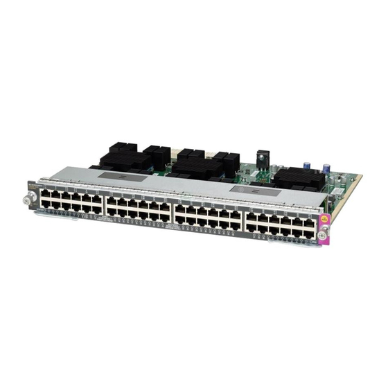
Appendix D Module Overview and Specifications Switching Modules Figure D-3 WS-X4548-GB-RJ45V-E 48-Port IEEE-Compliant PoE 10/100/1000BASE-T Switching Module To provide PoE with the 48-port PoE 10/100/1000BASE-T switching module in a Catalyst 4500 E-series switch, you must have an PoE-enabled power supply. All power supplies support PoE except the 1000 W and 1400 W AC power supplies. -
Page 145: Switching Module Leds
Appendix D Module Overview and Specifications Switching Modules Switching Module LEDs Each switching module has one LED labeled STATUS that provides information about the module and one numbered LED labeled LINK for each port on the module. Figure D-5 shows the Gigabit Ethernet port and status LEDs. -
Page 146: Hot-Swapping Feature
Appendix D Module Overview and Specifications Hot-Swapping Feature Table D-3 Switching Module LEDs (continued) Color/State Description Flashing The link has been disabled due to a hardware failure. orange No signal is detected. 1. Used on the WS-X4232-L3 Ethernet routing module. 2. - Page 147 I N D E X description 1-25 Numerics environmental monitoring 1-29 10/100BASE-T figure 1-26, 4-3 Ethernet management port handling (figure) port LEDs 5-8, D-7 installing 1000BASE-T removing interfaces 1-3, 1-6, 1-10, 1-14 replacing 1000BASE-X source circuit requirements Ethernet interfaces 1-17 troubleshooting port and status LEDs (figure) 5-8, D-7...
- Page 148 Index Catalyst 4503-E switches console port chassis dimensions connecting to features description front view conventions power requirements warnings repacking specifications Catalyst 4506-E switches attaching cable guides (figure) DC-input power supplies chassis dimensions connecting system ground features description 1-25 front view environmental monitoring 1-29 installing in racks (figure)
- Page 149 Index description Ethernet management ports Gigabit Ethernet LEDs See 1000BASE-T network switching not supported (note) See 1000BASE-X troubleshooting GOOD LEDs checking troubleshooting verifying power supply status 4-13 FAIL LEDs grounding checking connecting systems verifying power supply status 4-13 ground wire fan assemblies figure 4-10...
- Page 150 Index installing AC-input power supplies 4-4 to 4-8 OUTPUT FAIL LED DC-input power supplies 4-8 to 4-13 environmental monitoring 1-29 fan assemblies 4-13 to 4-15 installing switches in racks 3-2 to 3-7 packaging materials port status LEDs 5-9, D-7 labels, chassis serial number POST See serial numbers LEDs...
- Page 151 Index Catalyst 4510R supported 1-15 LEDs serial numbers 5-18 switch load indicators shipping instructions show port command show system command site planning checklist 2-11 contacting 5-18 slots temperature Catalyst 4503-E switches (figure) Catalyst 4503-E switches Catalyst 4506-E switches (figure) Catalyst 4506-E switches Catalyst 4507 switches (figure) 1-9, 1-13 Catalyst 4507 switches...
- Page 152 Index Catalyst 4500 E-Series Switches Installation Guide IN-6 OL-13972-01...