Table of Contents
Advertisement
R E V I E W D R A F T — C I S C O C O N F I D E N T I A L
Catalyst 4500 E-Series Switches
Installation Guide
August 2010
Americas Headquarters
Cisco Systems, Inc.
170 West Tasman Drive
San Jose, CA 95134-1706
USA
http://www.cisco.com
Tel: 408 526-4000
800 553-NETS (6387)
Fax: 408 527-0883
Text Part Number: OL-13972-02
Advertisement
Table of Contents
Troubleshooting

Related Manuals for Cisco Cisco Line Card 4500 E-Series


Summary of Contents for Cisco Cisco Line Card 4500 E-Series
- Page 1 R E V I E W D R A F T — C I S C O C O N F I D E N T I A L Catalyst 4500 E-Series Switches Installation Guide August 2010 Americas Headquarters Cisco Systems, Inc. 170 West Tasman Drive San Jose, CA 95134-1706 http://www.cisco.com Tel: 408 526-4000...
- Page 2 OR ITS SUPPLIERS HAVE BEEN ADVISED OF THE POSSIBILITY OF SUCH DAMAGES. Cisco and the Cisco Logo are trademarks of Cisco Systems, Inc. and/or its affiliates in the U.S. and other countries. A listing of Cisco's trademarks can be found at www.cisco.com/go/trademarks.
-
Page 3: Table Of Contents
Statement 1071—Warning Definition Related Documentation Hardware Documents Software Documentation Cisco IOS Documentation Product Overview C H A P T E R Catalyst 4503-E Switch Catalyst 4506-E Switch Catalyst 4507R-E Switch Catalyst 4510R-E Switch Catalyst 4507R+E Switch Catalyst 4510R+E Switch Preparing for Installation... - Page 4 C H A P T E R Installation Process Rack-Mounting Guidelines Unpacking the Switch Installing the Switch in a Rack Required Installation Tools Installing the Catalyst 4500 E-Series Switches in a Rack Establishing the System Ground Connection Required Tools and Parts...
- Page 5 System Messages and Switching Modules Useful CLI Commands Troubleshooting Supervisor Engines System Messages and Supervisor Engines Useful CLI Commands Standby Supervisor Engine Problems Switch Self-reset Supervisor Ports Do Not Function Packet Loss Some Problems and Solutions Module Not Online Interface Problems...
- Page 6 6000 W Power Supply AC Power Cords Remote Power Cycling Feature Terminal Block Ferrite Bead Remote Power-Cycling Operation Environmental Monitoring Feature Power Redundancy Repacking a Switch A P P E N D I X Catalyst 4500 E-Series Switches Installation Guide A-10 A-11 A-13 A-15...
- Page 7 Initial Configuration for the Switch A P P E N D I X Connecting to the Switch Starting the Terminal-Emulation Software Connecting to a Power Source Entering the Initial Configuration Information IP Settings Performing the Initial Configuration N D E X...
- Page 8 Contents Catalyst 4500 E-Series Switches Installation Guide viii OL-13972-02...
- Page 9 Audience This guide is intended for technicians who will install a Catalyst 4500 E-series switch in a wiring closet rack. Only trained and qualified service personnel (as defined in IEC 60950 and AS/NZS3260) should install, replace, or service the equipment.
- Page 10 Description Repacking a Switch Provides instructions for repacking your Catalyst 4500 E-series switch in the event that you need to move the chassis or have to return it to the factory. Initial Configuration for Provides a very minimal configuration process. For full...
- Page 11 Preface Conventions Warnings use the following conventions: Statement 1071—Warning Definition IMPORTANT SAFETY INSTRUCTIONS Warning This warning symbol means danger. You are in a situation that could cause bodily injury. Before you work on any equipment, be aware of the hazards involved with electrical circuitry and be familiar with standard practices for preventing accidents.
- Page 12 Preface Conventions Warnung WICHTIGE SICHERHEITSHINWEISE Dieses Warnsymbol bedeutet Gefahr. Sie befinden sich in einer Situation, die zu Verletzungen führen kann. Machen Sie sich vor der Arbeit mit Geräten mit den Gefahren elektrischer Schaltungen und den üblichen Verfahren zur Vorbeugung vor Unfällen vertraut. Suchen Sie mit der am Ende jeder Warnung angegebenen Anweisungsnummer nach der jeweiligen Übersetzung in den übersetzten Sicherheitshinweisen, die zusammen mit diesem Gerät ausgeliefert wurden.
- Page 13 Preface Conventions Varning! VIKTIGA SÄKERHETSANVISNINGAR Denna varningssignal signalerar fara. Du befinner dig i en situation som kan leda till personskada. Innan du utför arbete på någon utrustning måste du vara medveten om farorna med elkretsar och känna till vanliga förfaranden för att förebygga olyckor. Använd det nummer som finns i slutet av varje varning för att hitta dess översättning i de översatta säkerhetsvarningar som medföljer denna anordning.
- Page 14 Preface Conventions Aviso INSTRUÇÕES IMPORTANTES DE SEGURANÇA Este símbolo de aviso significa perigo. Você se encontra em uma situação em que há risco de lesões corporais. Antes de trabalhar com qualquer equipamento, esteja ciente dos riscos que envolvem os circuitos elétricos e familiarize-se com as práticas padrão de prevenção de acidentes. Use o número da declaração fornecido ao final de cada aviso para localizar sua tradução nos avisos de segurança traduzidos que acompanham o dispositivo.
- Page 15 Preface Conventions Catalyst 4500 E-Series Switches Installation Guide xiii OL-13972-02...
-
Page 16: Related Documentation
Catalyst 4900M platforms use the same software configuration guide, command reference guide, and system message guide. Refer to the following home pages for additional information: • Catalyst 4500 Series Switch Documentation Home http://www.cisco.com/go/cat4500/docs Catalyst 4900 Series Switch Documentation Home •... -
Page 17: Hardware Documents
URLs: • Catalyst 4500 Series release notes http://www.cisco.com/en/US/products/hw/switches/ps4324/prod_release_notes_list.html Catalyst 4948 Series and Catalyst 4948E release notes • http://www.cisco.com/en/US/products/ps6021/prod_release_notes_list.html Cisco ME 4900 Series Ethernet Switch release notes • http://www.cisco.com/en/US/docs/switches/lan/catalyst4500/release/note/OL_11511.html OL-13972-02 Related Documentation Catalyst 4500 E-Series Switches Installation Guide... -
Page 18: Obtaining Documentation And Submitting A Service Request
Related Documentation Software documents for the Catalyst 4500 Classic, Catalyst 4500 E-Series, Catalyst 4900, and Cisco ME 4900 Series Ethernet Switches • Catalyst 4500 Series Software Configuration Guide http://www.cisco.com/en/US/products/hw/switches/ps4324/products_installation_and_configurati on_guides_list.html • Catalyst 4500 Series Software Command Reference http://www.cisco.com/en/US/products/hw/switches/ps4324/prod_command_reference_list.html Catalyst 4500 Series Software System Message Guide •... -
Page 19: Product Overview
Product Overview This chapter describes the Catalyst 4500 E-series switches and contains these sections: Catalyst 4503-E Switch, page 1-2 • Catalyst 4506-E Switch, page 1-6 • • Catalyst 4507R-E Switch, page 1-10 • Catalyst 4510R-E Switch, page 1-15 • Catalyst 4507R+E Switch, page 1-19 Catalyst 4510R+E Switch, page 1-23 •... - Page 20 Catalyst 4503-E Switch Catalyst 4503-E Switch The Catalyst 4503-E switch is a 3-slot horizontal chassis supporting redundant power supplies, a single supervisor engine, and slots for up to two modules. switch with the chassis major features identified. Figure 1-1 REM OVE...
-
Page 21: Chapter 1 Product Overview
Chapter 1 Product Overview Table 1-1 Catalyst 4503-E Switch Features Feature Description Chassis Three horizontal slots. Slots are numbered from 1 (top) to 3 (bottom). Supervisor engines • Note • • Note Modules • • • Backplane 48 Gbps full duplex per slot (96 Gbps) Port density •... -
Page 22: Catalyst 4503-E Switch
Catalyst 4503-E Switch Table 1-1 Catalyst 4503-E Switch Features (continued) Feature Description Inline power Integrated support, 820 W per switching module Fan tray • • • Power supply • • • Note Catalyst 4500 E-Series Switches Installation Guide The chassis supports one hot-swappable fan tray. One fan tray model is... - Page 23 Chapter 1 Product Overview Table 1-2 lists the environmental and physical specifications of the Catalyst 4503-E switch. Table 1-2 Catalyst 4503-E Switch Specifications Item Specification Temperature, ambient • • Humidity (RH), ambient • (noncondensing) • Altitude, –196 to 6561 ft (–60 to 2000 m)
- Page 24 Catalyst 4506-E Switch Catalyst 4506-E Switch The Catalyst 4506-E switch is a 6-slot horizontal chassis supporting redundant power supplies, redundant supervisor engines, and slots for up to five modules. Catalyst 4506-E switch with the chassis major features identified. Figure 1-2...
- Page 25 Chapter 1 Product Overview Table 1-3 Catalyst 4506-E Switch Features Feature Description Chassis Six horizontal slots. Slots are numbered from 1 (top) to 6 (bottom). Supervisor engines • Note • • Modules • • • Backplane 48 Gbps full duplex per slot (240 Gbps) Port density •...
-
Page 26: Catalyst 4506-E Switch
Catalyst 4506-E Switch Table 1-3 Catalyst 4506-E Switch Features (continued) Feature Description Fan tray • • • Power supply • • • Note Catalyst 4500 E-Series Switches Installation Guide The chassis supports one hot-swappable fan tray. One fan tray model is... - Page 27 Chapter 1 Product Overview Table 1-4 lists the environmental and physical specifications of the Catalyst 4506-E switch. Table 1-4 Catalyst 4506-E Switch Specifications Item Specification Temperature, ambient • • Humidity (RH), ambient • (noncondensing) • Altitude, –196 to 6561 ft (–60 to 2000 m)
- Page 28 Catalyst 4507R-E Switch Catalyst 4507R-E Switch The Catalyst 4507R-E switch is a 7-slot horizontal chassis supporting redundant power supplies, redundant supervisor engines, and slots for up to six modules. Catalyst 4507R-E switch with the chassis major features identified. Figure 1-3...
- Page 29 Supervisor engines must be installed in slot 3 and in slot 4. Supervisor engine redundancy is supported in this chassis. The Catalyst 4507R-E switch supports 1+1 supervisor-engine redundancy for integrated resiliency. Redundant supervisor engines help minimize network downtime. With the support of stateful switchover (SSO), the secondary supervisor engine serves as a backup to immediately take over after a primary supervisor failure.
-
Page 30: Catalyst 4507R-E Switch
Catalyst 4507R-E Switch Table 1-5 Catalyst 4507R-E Switch Features (continued) Feature Description Port density • • • • • • • • • Inline power Integrated support, 820 W per switching module Fan tray • Note • • Catalyst 4500 E-Series Switches Installation Guide 1-12 10/100 (RJ-45)—240 ports... - Page 31 Catalyst 4507R-E Switch Features (continued) Feature Description Power supply • • • Note Table 1-6 lists the environmental and physical specifications of the Catalyst 4507R-E switch. Table 1-6 Catalyst 4507R-E Switch Specifications Item Specification Temperature, ambient • • Humidity (RH), ambient •...
- Page 32 Catalyst 4507R-E Switch Table 1-6 Catalyst 4507R-E Switch Specifications (continued) Item Specification Dimensions (H x W x D) and • rack units (RU) • Weight • • Airflow Chassis fan tray: Right to left Power supply fan: Front to back...
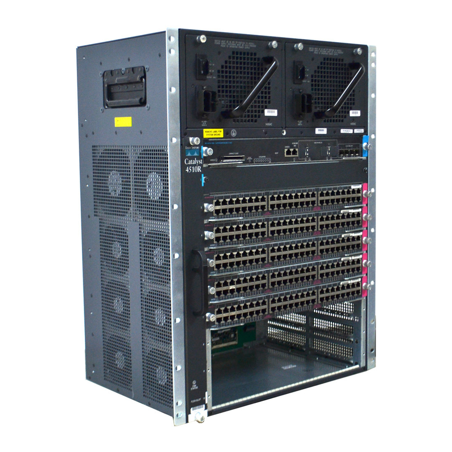
- Page 33 Chapter 1 Product Overview Catalyst 4510R-E Switch The Catalyst 4510R-E switch is a 10-slot horizontal chassis supporting redundant power supplies, redundant supervisor engines, and slots for up to nine modules. Catalyst 4510R-E switch with the chassis major features identified. Figure 1-4 Fan tray assembly Switching modules (slots 1–4 and 7–10)
-
Page 34: Catalyst 4510R-E Switch
Supervisor engines must be installed in slot 3 or in slot 4. Supervisor engine redundancy is supported in this chassis. The Catalyst 4510R-E switch supports 1+1 supervisor-engine redundancy for integrated resiliency. With the support of stateful switchover (SSO), the secondary supervisor engine serves as a backup to immediately take over after a primary supervisor failure. - Page 35 Chapter 1 Product Overview Table 1-7 Catalyst 4510R-E Switch Features (continued) Feature Description Fan tray • Note • • Power supply • • • Note OL-13972-02 The chassis supports one hot-swappable fan tray. One fan tray model is available: WS-X4582-E (located on the fan tray front panel) –...
- Page 36 Catalyst 4510R-E Switch Table 1-8 lists the environmental and physical specifications of the Catalyst 4510R-E switch. Table 1-8 Catalyst 4510R-E Switch Specifications Item Specification Temperature, ambient • • Humidity (RH), ambient • (noncondensing) • Altitude, operating –196 to 6561 ft (–60 to 2000 m) Sound pressure level •...
- Page 37 Chapter 1 Product Overview Catalyst 4507R+E Switch The Catalyst 4507R+E switch is a 7-slot horizontal chassis supporting redundant power supplies, redundant supervisor engines, and slots for up to five modules. Catalyst 4507R+E switch with the chassis major features identified. Figure 1-5...
-
Page 38: Catalyst 4507R+E Switch
Supervisor engines must be installed in slot 3 or in slot 4. Supervisor engine redundancy is supported in this chassis. The Catalyst 4507R+E switch supports 1+1 supervisor-engine redundancy. With the support of stateful switchover (SSO), the secondary supervisor engine serves as a backup to immediately take over after a primary supervisor failure. - Page 39 Chapter 1 Product Overview Table 1-9 Catalyst 4507R+E Switch Features (continued) Feature Description Port density • • • • • • • • • Inline power Integrated support, 820 W per switching module Fan tray • • • OL-13972-02 10/100 (RJ-45)—240 ports 10/100 with PoE (RJ-45)—240 ports...
- Page 40 Catalyst 4507R+E Switch Features (continued) Feature Description Power supply • • • Note Table 1-6 lists the environmental and physical specifications of the Catalyst 4507R+E switch. Table 1-10 Catalyst 4507R+E Switch Specifications Item Specification Temperature, ambient • • Humidity (RH), ambient •...
-
Page 41: Catalyst 4510R+E Switch
• • Note Catalyst 4510R+E Switch The Catalyst 4510R+E switch is a 10-slot horizontal chassis supporting redundant power supplies, redundant supervisor engines, and slots for up to nine modules. Catalyst 4510R+E switch with the chassis major features identified. OL-13972-02 19.15 x 17.22 x 12.50 in. (49 x 44 x 32 cm) 10 RU 45.5 lbs (20.68 kg) minimum... - Page 42 Figure 1-6 + E S e r Fan tray Switching modules (slots 1–4, 7–10) Table 1-11 describes the features of the Catalyst 4510R+E switch. Catalyst 4500 E-Series Switches Installation Guide 1-24 Catalyst 4510R+E Switch Chassis (Front View) i e s...
- Page 43 Supervisor engines must be installed in slot 3 or in slot 4. Supervisor engine redundancy is supported in this chassis. The Catalyst 4510R+E switch supports 1+1 supervisor engine redundancy for integrated resiliency. With the support of stateful switchover (SSO), the secondary supervisor engine serves as a backup to immediately take over after a primary supervisor failure.
- Page 44 Catalyst 4510R+E Switch Table 1-11 Catalyst 4510R+E Switch Features (continued) Feature Description Fan tray • • • Power supply • • • Note Catalyst 4500 E-Series Switches Installation Guide 1-26 The chassis supports one hot-swappable fan tray. One fan tray model is...
- Page 45 Chapter 1 Product Overview Table 1-12 lists the environmental and physical specifications of the Catalyst 4510R+E switch. Table 1-12 Catalyst 4510R+E Switch Specifications Item Specification Temperature, ambient • • Humidity (RH), ambient • (noncondensing) • Altitude, –196 to 6561 ft (–60 to 2000 m)
- Page 46 Chapter 1 Product Overview Catalyst 4510R+E Switch Catalyst 4500 E-Series Switches Installation Guide 1-28 OL-13972-02...
-
Page 47: Safety
Preparing for Installation Planning a proper location for the switch and the layout of your equipment rack or wiring closet is essential for successful system operation. You should install the switch in an enclosed, secure area, ensuring that only qualified personnel have access to the switch and control of the environment. -
Page 48: Chapter 2 Preparing For Installation
Multiple switches can be rack-mounted with little or no clearance above and below the chassis. However, when mounting a switch in a rack with other equipment, or when placing it on the floor near other equipment, ensure that the exhaust from other equipment does not blow into the air intake vent of the switch chassis. -
Page 49: Airflow
6-inch (15 cm) separation between a wall and the chassis air intake or a wall and the chassis hot air exhaust. In situations where the switch chassis are installed in adjacent racks, you should allow a minimum of 12-inches (30.5 cm) between the air intake of one chassis and the hot air exhaust of another chassis. -
Page 50: Fan Tray Assembly
Site Requirements • Verify that the enclosed or partially enclosed rack allows an adequate flow of air through the switch chassis as follows: – If the difference between the measured intake air temperature and the exhaust air temperature does not exceed 10°C (18°F), there is sufficient airflow in the rack. -
Page 51: Humidity
Chapter 2 Preparing for Installation Figure 2-1 45 06 Fan assembly Humidity High-humidity conditions can cause moisture migration and penetration into the system. This moisture can cause corrosion of internal components and degradation of properties such as electrical resistance, thermal conductivity, physical strength, and size. Extreme moisture buildup inside the system can result in electrical shorts, which can cause serious damage to the system. -
Page 52: Dust And Particles
Site Requirements Dust and Particles Fans cool power supplies and system components by drawing in room temperature air and exhausting heated air out through various openings in the chassis. However, fans also ingest dust and other particles, causing contaminant buildup in the system and increased internal chassis temperature. A clean operating environment can greatly reduce the negative effects of dust and other particles, which act as insulators and interfere with the mechanical components in the system. -
Page 53: Shock And Vibration
Chapter 2 Preparing for Installation To predict and remedy strong EMI, you may also need to consult experts in radio frequency interference Note (RFI). If you use twisted-pair cable in your plant wiring with a good distribution of grounding conductors, the plant wiring is unlikely to emit radio interference. -
Page 54: System Grounding
Site Requirements Besides these appliances, the greatest threats to a system power supply are surges or blackouts that are caused by electrical storms. Whenever possible, turn off the system and any peripherals, and unplug them from their power sources during thunderstorms. If a blackout occurs—even a temporary one—while the system is turned on, turn off the system immediately and disconnect it from the electrical outlet. - Page 55 Chapter 2 Preparing for Installation Table 2-1 Environment Commercial building is subjected to direct lightning strikes. For example, some places in the United States, such as Florida, are subject to more lightning strikes than other areas. Commercial building is located in an area where lightning storms frequently occur but is not subject to direct lightning...
-
Page 56: Maintaining Safety With Electricity
Site Requirements In installations where FXS modules are installed, supplemental grounding is required. Note Always ensure that all of the modules are completely installed and that the captive installation screws Note are fully tightened. In addition, ensure that all I/O cables and power cords are properly seated. These practices are normal installation practices and must be followed in all installations. -
Page 57: Preventing Electrostatic Discharge Damage
Chapter 2 Preparing for Installation • Use approved power cables only. You have been provided with one or more power cables with your chassis power supply that are intended for use in your country, based on the shipping location. Should you need to purchase additional power cables, ensure that they are rated for the product and for the voltage and current marked on the product’s electrical ratings label. - Page 58 Site Requirements After you install the system ground lug, follow these steps to correctly attach the ESD wrist strap: Attach the ESD wrist strap to bare skin as follows: Step 1 If you are using the ESD wrist strap supplied with the FRUs, open the wrist strap package and unwrap the ESD wrist strap.
-
Page 59: Power Requirements
Catalyst 4500 E-series switch power supplies which use power factor correction (PFC). Ferroresonant technology can cause the output voltage waveform to the switch to become distorted resulting in an undervoltage situation in the system. -
Page 60: Power Connection Guidelines For Dc-Powered Systems
Connection to the DC-input power supply requires one earth ground cable, one source DC (–), and one source DC return (+). The length of the cables depends on your switch location. These cables are not available from Cisco Systems. They are available from any commercial cable vendor. -
Page 61: Cabling Requirements
Site Preparation Checklist Table 2-2 lists the site-planning activities that you should complete before you install a Catalyst 4500 E-series switch. Completing each activity helps to ensure a successful switch installation. OL-13972-02 Cabling Requirements Catalyst 4500 E-Series Switches Installation Guide... - Page 62 Site Preparation Checklist Table 2-2 Task No. Planning Activity Space evaluation: • • • • • Environmental evaluation: • • • • • Power evaluation: • • • • Grounding evaluation: • Cable and interface equipment evaluation: • • • •...
-
Page 63: Installing The Switch
Before starting the installation procedures in this chapter, complete the site-planning checklist in Table 2-2 Chapter 2, “Preparing for Installation.” For information on installing the supervisor engine and switching modules and verifying switch Note operation, see the Catalyst 4500 Series Module Installation Guide. For information on configuring the switching modules, see the software configuration guide for your switch and software release. -
Page 64: Chapter 3 Installing The Switch
Installation Process Installation Process The process of installing the switch can be broken down into a series of tasks. These tasks are listed in Table 3-1. Table 3-1 Task Unpacking the switch Installing the switch Connecting the chassis to system... - Page 65 Chapter 3 Installing the Switch All of the Catalyst 4500 E-series switch chassis are designed to install in standard 19-inch racks. Note The rack must have sufficient vertical clearance to insert the chassis. The chassis heights are as • follows: Catalyst 4503-E switch—12.25 inches (31.12 cm) (7 RU)
-
Page 66: Unpacking The Switch
Do not discard the shipping cartons and poly bag when you unpack the switch. Flatten and store them. You will need the containers if you need to move or ship the switch in the future. Repacking instructions are provided in Installing the Switch in a Rack A rack-mount kit is included for mounting the switch in a standard 19-inch (48.3 cm) equipment rack... -
Page 67: Installing The Catalyst 4500 E-Series Switches In A Rack
Installing the Catalyst 4500 E-Series Switches in a Rack To install a Catalyst 4500 E-series switch in an equipment rack, follow these steps: Place the chassis on the floor or on a sturdy table near the rack. Step 1... - Page 68 Attach the cable guide, if needed, using the M3 screws provided in the cable management kit. The cable guide attaches to prethreaded holes in either L bracket. (See We recommend that you attach the cable guide to the right side of the switch chassis to prevent Note the network interface cables from obscuring switching module front panel LEDs.
-
Page 69: Establishing The System Ground Connection
Installing the Switch Establishing the System Ground Connection Figure 3-2 Attaching the Cable Guide to the Chassis (Catalyst 4506-E Switch Shown) 45 06 Verify that on all installed supervisor engines and switching modules, the ejector levers are completely Step 6 closed and that the captive installation screws are tight. -
Page 70: Required Tools And Parts
Crimp the grounding wire in the barrel of the grounding lug. Verify that the ground wire is securely Step 3 attached to the ground lug by holding the ground lug and gently pulling on the ground wire. Locate and remove the adhesive label covering the system grounding pad on the switch chassis. (See Step 4 Figure 3-3.) -
Page 71: Completing The Installation Process
Prepare the other end of the grounding wire and connect it to an appropriate grounding point at your site Step 7 to ensure adequate earth ground for the switch. Consult with your local electrician to determine the appropriate place to attach the gound wire. -
Page 72: Connecting The Supervisor Engine Console Port
With this console connection, you can configure the switch as described in Configuration for the Switch,” your switch’s software release, and monitor the software as the switch goes through its startup routine. If you move a supervisor engine from a Catalyst 4500 series chassis to a Catalyst 4503-E chassis or Note Catalyst 4506-E chassis, the supervisor engine must use Cisco IOS Release 12.2(37)SG or later releases. -
Page 73: Connecting The Supervisor Engine Uplink Ports
Chapter 3 Installing the Switch Connecting the Supervisor Engine Uplink Ports This section describes how to connect to the supervisor engine uplink ports. Some supervisor engine uplink ports may require the installation of transceivers into the supervisor engine port sockets. Refer to the applicable transceiver installation notes for instructions on how to correctly install the transceiver into your supervisor engine uplink port. - Page 74 Chapter 3 Installing the Switch Completing the Installation Process Catalyst 4500 E-Series Switches Installation Guide 3-12 OL-13972-02...
-
Page 75: Removal And Replacement Procedures
Removal and Replacement Procedures This chapter describes how to perform removal and replacement procedures for the following Catalyst 4500-E series field-replaceable units (FRUs): Removing and Installing the AC-Input Power Supplies, page 4-2 • Removing and Installing the DC-Input Power Supplies, page 4-8 •... -
Page 76: C H A P T E R 4 Removal And Replacement Procedures
The power supplies are hot-swappable, so in redundant mode, you will not need to power down the Note switch to replace or upgrade most power supplies. With dual power supplies running in combined mode, some chassis slots may lose power during an upgrade or power supply replacement. -
Page 77: Required Tools
10 0- 12 0V - 12 A 50 /6 0H AC input 2 receptacle AC input 2 on/off switch AC input 1 on/off switch Required Tools You need a flathead or Phillips-head screwdriver to perform these procedures. OL-13972-02 AC-Input Power Supply (Single-Input) -
Page 78: Removing An Ac-Input Power Supply
Removing and Installing the AC-Input Power Supplies Removing an AC-Input Power Supply To remove the AC-input power supply, follow these steps: Set the AC-input power supply power switch to the off (0) position (see Step 1 Figure 4-3 Power switch... - Page 79 Chapter 4 Removal and Replacement Procedures Figure 4-5 Use both hands to grasp and support a power supply. Caution Grasp the power supply handle with one hand. Place your other hand underneath to support the bottom Step 5 of the power supply, as shown in Figure 4-6 Slide the power supply out of the bay and set it aside.
-
Page 80: Installing An Ac-Input Power Supply
To install an AC-input power supply, follow these steps: Step 1 Remove the replacement power supply from its shipping packaging. Verify that the replacement power supply power switch is in the off (0) position. Step 2 Step 3 If necessary, remove the blank power supply cover from the empty power supply bay by removing the two Phillips-head screws. - Page 81 Step 12 Check the power supply and system status from the system console by entering show power command. For more information on this command, see the command reference publication for your switch. Step 13 If the LEDs or show power command output indicate a power problem or other system problem, see Chapter 5, “Troubleshooting,”...
-
Page 82: Removing And Installing The Dc-Input Power Supplies
To remove a DC-input power supply, follow these steps: Step 1 Turn off the in-line power switch on the DC-input power supply front panel. (This step applies to the single input power supply only, PWR-C45-1400DC-P; the triple-input power supply, PWR-C45-1400DC, does not have this switch.) Verify that power is off to the DC circuit on the power supply that you are removing. - Page 83 Figure 4-10 Output Fail LED Fan OK LED Input OK 1, 2, 3 LEDs Captive screw Power switch 1, 2, 3 Step 4 Disconnect the DC-input wires from the terminal block. Disconnect the ground wire last (see Figure 4-11 Figure Warning When installing or replacing the unit, the ground connection must always be made first and disconnected last.
- Page 84 Removing and Installing the DC-Input Power Supplies Figure 4-11 RS-485 serial communnication connector DC-input wires Negative Positive Ground Grounding lug Grounding lug nuts Figure 4-12 Grounding lugs (2) Grounding lug nut Loosen the two captive screws on the power supply. (See Step 5 power supply.
-
Page 85: Installing A Dc-Input Power Supply
Chapter 4 Removal and Replacement Procedures Step 6 Grasp the power supply handle with one hand. Place your other hand underneath as you slowly pull the power supply out of the chassis power supply bay (see Figure 4-14 Step 7 If the chassis power supply bay is to remain empty, install a blank power supply filler plate (WS-C4KE-PS-CVR) over the opening and secure it with the mounting screws. - Page 86 DC power source. In the event of a power source failure, if the second source is still available, it can maintain maximum overcurrent protection for each power connection. Remove any safety flag and lockout devices or any tape from the source DC circuit breaker switch handle Step 8 and restore power by moving the circuit breaker switch handle to the on (|) position.
-
Page 87: Removing And Installing The Chassis Fan Tray Assembly
Check the power supply and system status from the system console by entering the show power command. For more information on the commands, see the command reference publication for your switch and software. If the LEDs or the show power command (Cisco IOS) output indicate a power problem or other system... -
Page 88: Installing The Fan Tray Assembly
Removing and Installing the Chassis Fan Tray Assembly Figure 4-15 45 06 Captive installation screws Grasp the fan tray assembly handle and slide the fan tray assembly out of the chassis; gently move it side Step 2 to side if necessary to unseat it from the backplane. Remove the fan tray assembly from the chassis and set it aside. -
Page 89: Verifying The Installation
Listen for the fans; you should immediately hear them operating. If you do not hear them, ensure that Step 1 the fan tray assembly is inserted completely in the chassis and that the faceplate is flush with the switch back panel. - Page 90 Removing and Installing the Backplane Modules Generic switching module replacement procedures are documented at Note http://www.cisco.com/en/US/docs/switches/lan/catalyst4500/hardware/configuration/notes/gM dCf_nt.html Locate the backplane modules that you need to replace. Step 6 with the supervisor engines and switching modules removed. Figure 4-16 Catalyst 4500 E-Series Switches Installation Guide 4-16 Catalyst 4507R-E Backplane Clock module...
- Page 91 Chapter 4 Removal and Replacement Procedures Step 7 If you are removing a clock module, remove the two screws that secure the clock module to the backplane. Step 8 Locate the seating levers on both sides of the connector for the module that you want to replace. (See Figure 4-17.) Figure 4-17...
- Page 92 Removing and Installing the Backplane Modules Figure 4-19 Remove the replacement module from its packaging. Be careful not to touch the chips or the gold edge Step 11 contacts on the module. Carefully position the replacement module in the socket, and gently push the module down to seat it in Step 12 the socket.
-
Page 93: Verifying The New Modules
3, 4 and 7. You need to reinsert and reseat the modules in those slots. If the switch has already started up, you may also verify the correct function of the new modules with the show logging command. -
Page 94: Required Tools And Components
Installing the Remote Power Cycling Feature Control Wires (Optional) Required Tools and Components The following tools and components are required to perform this procedure: Relay controller box. • We strongly recommend that you purchase a relay controller box that uses a NO (normally open) relay to control the remote power cycling. -
Page 95: Installing The Ferrite Bead
Chapter 4 Removal and Replacement Procedures Figure 4-22 Relay controller power You are now ready to install the ferrite bead on the control wires. Follow the installation instructions supplied in the package containing the ferrite bead or the installation procedure in the next section. Installing the Ferrite Bead The ferrite bead is a passive device that limits high-frequency interference on interface and control cables, and it is only required when you install the remote power-cycling feature that is supported only... - Page 96 Installing the Remote Power Cycling Feature Control Wires (Optional) To install the ferrite bead on the remote power-cycling control wires, follow these steps: Remove the ferrite bead and the two plastic ties from the plastic bag. Step 1 Open the ferrite bead as shown in Step 2 Place the two remote power-cycling control wires (18 AWG maximum) in the ferrite bead as shown in Step 3...
-
Page 97: Troubleshooting
Troubleshooting This chapter describes how to perform basic troubleshooting on the Catalyst 4500 E-series switch. Problems with the initial startup are often caused by a switching module that has become dislodged from the backplane or a power cord that is disconnected from the power supply. -
Page 98: Chapter 5 Troubleshooting
If all of these conditions are met and the hardware installation is complete, refer to the software configuration guide and command reference publications for your switch so that you can troubleshoot the software. If any of these conditions is not met, use the procedures in this chapter to isolate and, if possible, resolve the problem. -
Page 99: Using Leds To Identify Startup Problems
LEDs. By checking the LEDs, you can determine when and where the system failed in the startup sequence. If you have problems after the switch is on, refer to the following subsystem troubleshooting information and the configuration procedures in the software configuration guide for your switch. -
Page 100: System Messages
System Messages Step 5 If the boot information and system banner are not displayed, verify that the terminal is set for 9600 baud, 8 data bits, no parity, and 1 stop bit and connected properly to the console port. System Messages System messages appear on the console if you have enabled console logging or appear in the syslog if you have enabled syslog. -
Page 101: System Messages And Power Problems
See the Problems” section on page If the LED labeled FAN OK fails to light when the switch is connected to a good power source with a Step 6 known good power cord, there is a malfunction in the fan that cools the power supply. -
Page 102: Useful Cli Commands
2 as in the err-disable state in the output of the show power command. When the power supply in bay 1 is removed, the switch recognizes the power supply in bay 2, and you may then put a new matching power supply in bay 1. -
Page 103: System Messages And Fan Problems
(WS-X4K-CLOCK-E=) are available for serviceability. The following conditions indicate that you may need to replace the redundancy modules and clock module: The switch powers down and stays down for a few minutes to a few days for no clear reason. • OL-13972-02... -
Page 104: Troubleshooting Switching Modules
10/100 B Switching Module LEDs Indicates the results of a series of self-tests and diagnostic tests performed by the switch. All the tests pass. A test other than an individual port test failed. System boot, self-test diagnostics running, or the module is disabled. -
Page 105: System Messages And Switching Modules
Chapter 5 Troubleshooting Table 5-1 Color/State Description Orange Flashing orange Port Status Green Orange Flashing orange 1. LEDs labeled 1 through the number of ports on the switching module are the individual port link LEDs. System Messages and Switching Modules Connect a terminal to the console port, and look for any of the following system messages: C4K_CHASSIS-3-LINECARDMUXBUFFERTOSUPALIGNMENTWRONG C4K_CHASSIS-3-LINECARDNOTVALIDINSLOT... -
Page 106: Troubleshooting Supervisor Engines
Orange System boot or diagnostic test is in progress. Module is disabled. If the switch is operational, this display indicates the current traffic load over the backplane (as an approximate percentage). Indicates the status of the 10/100BASE-T Ethernet management port or uplink ports. - Page 107 Some problems with supervisor engines are due to backplane connections that are not fully seated. If removing and reinserting the supervisor engine and then restarting the switch does not solve the problem, you may need to call Cisco TAC and replace the supervisor engine.
-
Page 108: Useful Cli Commands
ROMmon mode or in continuous reboot. If the standby supervisor engine is in either of these two states, refer to: http://www.cisco.com/en/US/products/hw/switches/ps663/products_configuration_example09186a008 0094ecf.shtml switch# show module Ports Card Type ----+-----+--------------------------------------+-----------------+----------- 1000BaseX (GBIC) Supervisor(active) -
Page 109: Switch Self-Reset
Switch Self-reset If the switch has reset or rebooted on its own, verify that the power source for the switch did not fail. If you use an uninterruptable power supply (UPS), make sure that the UPS does not have any problems. -
Page 110: Some Problems And Solutions
If the status is “power-deny,” the switch does not have enough power available to power this module. Enter the show power command in order to confirm whether enough power is available. For more information, refer to the “Environmental Monitoring and Power Management”... -
Page 111: Interface Problems
If the module still does not come online, create a service request with Cisco Technical Support in order to troubleshoot further. Use the log of the switch output that you collected in the above output and the troubleshooting steps that you performed. -
Page 112: Nic Compatibility Issues
If you are unable to get a console connection or the command output indicates a failure, contact Cisco Technical Support. If the switch does not boot and fails self diagnostics during the boot sequence, capture the console output of the startup sequence then contact Cisco Technical Support. -
Page 113: Boot Problems
Boot Problems If the switch is in a continuous boot loop, is in ROMmon mode, or does not have a system image, there is mostly likely not a hardware problem. The supervisor engine operates in a continuous loop if you have not set the boot variable correctly and you have set the configuration register to 0x2102. -
Page 114: Contacting The Cisco Technical Assistance Center
Step 8 If the host is in the same subnet as the switch interface, make sure the switch interface and the switch port to which the host is connected are assigned to the same VLAN (use the show interface and show port commands to check). - Page 115 Chapter 5 Troubleshooting • Maintenance agreement or warranty information Brief description of the problem • Console captures related to your problem • Brief explanation of the steps you have already taken to isolate and resolve the problem • See the “Obtaining Documentation and Submitting a Service Request”...
- Page 116 Chapter 5 Troubleshooting Contacting the Cisco Technical Assistance Center Catalyst 4500 E-Series Switches Installation Guide 5-20 OL-13972-02...
-
Page 117: Power Supply Specifications
Note All Catalyst 4500 E-series switch AC-input power supplies require single-phase source AC. The source AC can be out of phase between multiple power supplies or multiple AC-power plugs on the same power supply because all AC power supply inputs are isolated. Each chassis power supply should have its own dedicated branch circuit: 15 A or 20 A for North America and circuits sized to local and national codes for International locations. - Page 118 • Catalyst 4510R-E (the 1000 W AC-input power supply can be installed in the Catalyst 4510R-E • switch chassis; however power management is required) Catalyst 4510R+E (the 1000 W AC-input power supply can be installed in the Catalyst 4510R+E •...
-
Page 119: Appendix A Power Supply Specification
Appendix A Power Supply Specifications 1000 W AC-Input Power Supply Specifications Table A-1 lists the specifications for the 1000 W AC-input power supply. Table A-1 Item AC-input type AC-input voltage AC-input current AC-input frequency Branch circuit requirement OL-13972-02 1000 W AC-Input Power Supply Specifications Specification Autoranging input with power factor correction (PFC) Note... -
Page 120: W Ac-Input Power Supply
1000 W AC-Input Power Supply Table A-1 Item Power supply output capacity Power supply output Output holdup time Maximum kVA rating Max heat dissipation Minimum software requirement Power over Ethernet 1. A Catalyst 4503 with a Catalyst 4500 series Supervisor Engine II-Plus TS and a 1000 W power supply will be able to provide 158.4 W of Power over Ethernet (PoE) to ports on the supervisor engine. - Page 121 Appendix A Power Supply Specifications Table A-3 Locale North America CAB-US515-C15-US= Australia, New Zealand Europe (except Italy) Italy United Kingdom Argentina 1. Plug contains a 13 A fuse. OL-13972-02 1000 W AC Power Supply Power Cords Power Cord Part Number Length 8.2 ft (2.5 m) 15 A, 125 VAC (was CAB-7KAC=)
- Page 122 • Catalyst 4510R-E (the 1300 W AC-input power supply can be installed in the Catalyst 4510R-E • switch chassis; however power management is required) Catalyst 4510R+E (the 1300 W AC-input power supply can be installed in the Catalyst 4510R+E •...
- Page 123 Appendix A Power Supply Specifications Table A-4 Item AC-input type AC-input voltage AC-input current AC-input frequency Branch circuit requirement Power supply output capacity OL-13972-02 1300 W AC-Input Power Supply Specifications Specification Autoranging input with power factor corrector Note Power factor correction is a standard feature on all Catalyst 4500 E-series AC-input power supplies.
-
Page 124: W Ac-Input Power Supply Specifications
1300 W AC-Input Power Supply Table A-4 Item Power supply output Output holdup time Maximum kVA rating Max heat dissipation Minimum software requirement Power over Ethernet (PoE) Table A-5 lists the 1300 W AC-input power supply LEDs and their meanings. Table A-5 INPUT OK FAN OK... - Page 125 Appendix A Power Supply Specifications Table A-6 Locale North America CAB-US520-C19-US= Australia, New Zealand Europe (except Italy) Italy United Kingdom Argentina North America (locking) 200–240 VAC operation OL-13972-02 1300 W AC-Input Power Supply Power Cords Power Cord Part Number Length 14 ft (4.3 m) 20 A, 125 VAC (was CAB-7513AC=) CAB-A3112-C19-AUS=...
- Page 126 1400 W AC-Input Power Supply Table A-6 Locale North America (nonlocking) 200–240 VAC operation Europe South Africa, India International Israeli UPS 220V 1400 W AC-Input Power Supply The 1400 W AC-input power supply (PWR-C45-1400AC), shown in following Catalyst 4500 E-series switches: Catalyst 4503-E •...
- Page 127 Appendix A Power Supply Specifications Figure A-3 AC-input receptacle Power on/off switch 1400 W AC-Input Power Supply Specifications Table A-7 lists the specifications for the 1400 W AC-input power supply. Table A-7 Item AC-input type AC-input voltage AC-input current AC-input frequency...
-
Page 128: W Ac-Input Power Supply
1400 W AC-Input Power Supply Table A-7 Item Branch circuit requirement Power supply output Power supply output (AC supply) Output holdup time Max heat dissipation Maximum kVA rating Minimum software requirement Power over Ethernet 1. A Catalyst 4503-E with a Catalyst 4500 E-series Supervisor Engine II-Plus TS and a 1400W AC power supply provides 158.4 W of PoE to ports on the supervisor engine. -
Page 129: W Power Supply Ac Power Cords
Appendix A Power Supply Specifications Table A-8 INPUT OK FAN OK OUTPUT FAIL 1400 W Power Supply AC Power Cords Table A-9 lists the specifications for the AC power cords that are available for the 1400 W AC-input power supply. The table includes a power plug illustration for each power cord. Note All 1400 W power supply power cords have an IEC60320/C19 appliance plug at one end. - Page 130 1400 W AC-Input Power Supply Table A-9 Locale Italy United Kingdom Argentina North America (locking) 200–240 VAC operation North America (nonlocking) 200–240 VAC operation Europe South Africa, India International Catalyst 4500 E-Series Switches Installation Guide A-14 1400 W AC-Input Power Supply Power Cords (continued) Power Cord Part Number Length CAB-C2316-C19-IT=...
- Page 131 Do not install the 1400 W DC power supply with any other power supply under any circumstances. Caution Doing so can seriously damage your switch. Figure A-4 The 1400W DC-input power supply can be used with the Catalyst 4500 Series AC Power Shelf (PWR-P4502-1PSU).
- Page 132 31 A @ –60 VDC (data only) 180 A maximum @ –48 VDC input (data and inline devices) The input power is configurable in the CLI. The Cisco IOS command is power dc input. Configure the switch software to match the requirements of your switch. Data •...
-
Page 133: W Dc-Input Power Supply
Appendix A Power Supply Specifications Table A-11 list the 1400 W DC-input power supply LEDs and their meanings. Table A-11 INPUT OK FAN OK OUTPUT FAIL In-line PWR Table A-12 lists the chassis specific power usage numbers for the 1400 W DC-input power supply. Table A-12 Chassis-Specific Power Usage Chassis... - Page 134 1400 W Triple-Input DC-Input Power Supply 1400 W Triple-Input DC-Input Power Supply The 1400 W triple-input DC-input power supply (PWR-C45-1400DC), shown in supported in the following Catalyst 4500 E-series switches. Catalyst 4503-E • Catalyst 4506-E • Catalyst 4507R-E • Catalyst 4510R-E •...
- Page 135 Appendix A Power Supply Specifications Table A-13 Item Power supply output DC input terminal block Output holdup time Maximum kVA rating Max heat dissipation Minimum software requirement Power over Ethernet Catalyst 4503-E Specific Power Usage (data only) Maximum draw Maximum input Current draw at –40.5 V (min voltage) Current draw at –72 V (max...
-
Page 136: W Triple-Input Dc-Input Power Supply
1367 W 1. The kVA rating listed for the power supply should be used as the sizing criteria for both UPS outputs as well as standard circuits and transformers to power a switch. Table A-14 list the 1400 W triple-input DC-input power supply LEDs and their meanings. - Page 137 Appendix A Power Supply Specifications Table A-15 Input Source DC Mode Connections 2, 3 1, 2, 3 Power output also depends on whether two supplies are used, and whether they are in redundant or combined mode. power provided to the supply. Table A-16 PS1 input 1 PS1 input 2 or 3...
-
Page 138: W Dc Triple-Input Power Supply Operational Modes
1400 W Triple-Input DC-Input Power Supply 1400 W DC Triple-Input Power Supply Operational Modes The 1400 W triple-input DC-input power supply (data only) allows added redundancy by providing terminals for two DC inputs rated at 15 A and one rated at 12.5 A per power supply. This power supply has five operational modes depending on the inputs receiving power. - Page 139 Appendix A Power Supply Specifications Table A-19 Input Approximate Number Input Current 6.25 A @ –40.5 / –44 VDC 7.5 A @ –40.5 / –44 VDC 7.5 A @ –40.5 / –44 VDC In a redundant configuration with all inputs supplied, there must be a 100 W minimum system load or Note the OUTPUT FAIL LED shows a false failure.
- Page 140 Catalyst 4510R-E • Catalyst 4507R+E • Catalyst 4510R+E • Figure A-6 AC-in receptical On/off power switch 2800 W AC-Input Power Supply Specifications Table A-21 lists the specifications for the 2800 W AC-input power supply. Table A-21 Item AC-input type AC-input voltage...
- Page 141 Appendix A Power Supply Specifications Table A-21 Item Branch circuit requirement Power supply output capacity Power supply output Output holdup time Maximum kVA rating Max heat dissipation Minimum software requirement Power over Ethernet OL-13972-02 2800 W AC-Input Power Supply Specifications (continued) Specification Each chassis power supply should have its own dedicated, fused-branch circuit:...
-
Page 142: W Ac-Input Power Supply
2800 W AC-Input Power Supply Table A-22 describes the 2800 W AC-input power supply LEDs and their meanings. Table A-22 INPUT OK OUTPUT FAIL FAN OK Catalyst 4500 E-Series Switches Installation Guide A-26 2800 W AC-Input Power Supply LEDs Color/State Description Indicates whether the input voltage is within the required range:... - Page 143 Appendix A Power Supply Specifications 2800 W Power Supply AC Power Cords Table A-23 lists the specifications for the AC power cords that are available for the 2800 W AC-input power supply. Note All 2800 W AC-input power supply power cords have an IEC60320/C19 appliance plug at one end. Table A-23 Locale North America...
-
Page 144: W Ac-Input Power Supply Specifications
10 0- 12 0V - 12 A 50 /6 0H AC-input 2 receptacle AC-input 2 power on/off switch AC-input 1 power on/off switch 4200 W AC-Input Power Supply Specifications Table A-24 lists the specifications for the 4200 W AC-input power supply. -
Page 145: W Ac-Input Power Supply
Appendix A Power Supply Specifications Table A-24 Item AC-input type AC-input voltage AC-input current AC-input frequency Branch circuit requirement OL-13972-02 4200 W AC-Input Power Supply Specifications Specification Autoranging input with power factor corrector Note Power factor correction is a standard feature on all Catalyst 4500 E-series AC-input power supplies. - Page 146 4200 W AC-Input Power Supply Table A-24 Item Power supply output capacity 1050 W operation 2100 W operation 4200 W operation Power supply output Output holdup time Maximum kVA rating Catalyst 4500 E-Series Switches Installation Guide A-30 4200 W AC-Input Power Supply Specifications (continued) Specification The power supply output capacity is dependent on the number of AC power cords (1 or 2) attached, the source AC voltage (110 VAC...
- Page 147 Appendix A Power Supply Specifications Table A-24 Item Max heat dissipation Minimum software requirement Power over Ethernet Table A-25 describes the 4200 W AC-input power supply LEDs and their meanings. Table A-25 INPUT OK OUTPUT FAIL FAN OK The 4200 W AC power supply should not be used in mixed-voltage configurations. All the inputs in a Note chassis must be at the same voltage (110 VAC or 220 VAC).
-
Page 148: W Power Supply Ac Power Cords
4200 W AC-Input Power Supply Table A-26 Source AC to Power Supplies 110 VAC to one input on supply 1 and one 100 VAC to one input on power supply 2 110 VAC to both inputs on power supply 1 and 110 VAC to both inputs on power supply 2, or one 220 VAC input to power supply 1 and one 220 VAC input to power supply 2... - Page 149 Appendix A Power Supply Specifications Table A-28 Locale North America 120 VAC operation North America (locking) 200–240 VAC operation North America (nonlocking) 200–240 VAC operation Europe International (including Argentina and South Africa) Australia Argentina Italy United Kingdom OL-13972-02 4200 W AC-Input Power Supply Power Cords Power Cord Part Number Length CAB-US515P-C19-US...
- Page 150 6000 W AC-Input Power Supply Table A-28 Locale Israeli UPS 220V 6000 W AC-Input Power Supply The 6000 W AC-input power supply (PWR-C45-6000ACV), shown in following Catalyst 4500 E-series switch chassis: Catalyst 4503-E • Catalyst 4506-E • Catalyst 4507R-E •...
-
Page 151: W Power Supply Specifications
Appendix A Power Supply Specifications Figure A-8 AC-input 2 receptacle AC-input 2 on switch AC-input 1 on switch 6000 W Power Supply Specifications Table A-29 lists the specifications for the 6000 W AC-input power supplies. Table A-29 Item AC-input type... - Page 152 Power over Ethernet 1. The kVA rating listed for the power supply should be used as the sizing criteria for both UPS outputs as well as standard circuits and transformers to power a switch. Table A-30 list the 6000 W AC-input power supply LEDs and their meanings.
- Page 153 Appendix A Power Supply Specifications Table A-30 INPUT OK FAN OK OUTPUT FAIL The 6000 W AC-input power supply should not be used in mixed-voltage configurations. All the inputs Note in a chassis must be at the same voltage (110 VAC or 220 VAC). Table A-31 shows the wattage output possible from a 6000 W AC-input power supply in redundant mode.
-
Page 154: W Power Supply Ac Power Cords
6000 W AC-Input Power Supply Table A-32 Both PS with one input at 110 VAC One 110 VAC input to one PS, two 110 VAC inputs to the other PS Both PS with two 110 VAC inputs Both PS with one 220 VAC input Two 220 VAC inputs to one PS, one 220 VAC input to the other PS Both PS with two 220 VAC inputs... - Page 155 Appendix A Power Supply Specifications Table A-33 Locale North America (locking) 200–240 VAC operation Australia Argentina China 200–240 VAC operation Switzerland India United Kingdom Italy OL-13972-02 6000 W AC-Input Power Supply Power Cords (continued) Power Cord Part Number Length CAB-AC-2800W-TWLK= 13.6 ft (4.1 m) CAB-L620P-C19-US=...
-
Page 156: Remote Power Cycling Feature
6000 W AC-Input Power Supply Table A-33 Locale Israel Brazil UPS 220V Remote Power Cycling Feature The 6000 W AC-input power supply is equipped with a remote power cycling feature that allows you to remotely turn on or turn off the power supply through an external relay controller box. a typical remote power on/off setup. -
Page 157: Remote Power Cycling Feature
Remote Power-Cycling Operation This feature allows you to remotely power cycle the Catalyst 4500 E-series switch using any appropriate third-party relay controller. This feature eliminates the need for you to have access to the supervisor engine console or CLI to control power cycling. -
Page 158: Environmental Monitoring Feature
For a 1400 W DC power supply, the main power switch has an input range of –40.5 to –72 VDC, while the –48 V PoE operates over a range of –40.5 to –56 VDC. The PoE either fails to start or shuts down if exposed to greater than –56 VDC input. -
Page 159: Repacking A Switch
Repacking a Switch This appendix describes how to return your Catalyst 4500 E-series switch to the factory and how to repack your switch in preparation for shipping. for the Catalyst 4500 E-series chassis. Table B-1 Chassis Catalyst 4503-E Catalyst 4506-E... -
Page 160: Appendix B Repacking A Switch
Figure B-1 Documentation and accessories Packing foam Packing foam Packing foam Catalyst 4500 E-Series Switches Installation Guide Catalyst 4500 E-Series Switch Packing Material Appendix B Repacking a Switch Packing carton OL-13972-02... -
Page 161: Initial Configuration For The Switch
For additional information about the Catalyst 4500 E-series switches (including configuration examples and troubleshooting information), see the documents listed on this page: http://preview.cisco.com/en/US/products/hw/switches/ps4324/tsd_products_support_series_home.html You need to provide the Category 5 straight-through cables to connect the switch ports to other Note Ethernet devices. -
Page 162: Connecting To The Switch
Step 1 connector on the switch, and then connect the other end of the power cable to a grounded AC outlet. If you are using a DC-input power supply, see the instructions on how to install the DC power supply in Step 2 Chapter 3, “Installing the Switch.”... -
Page 163: Entering The Initial Configuration Information
Appendix C Initial Configuration for the Switch As the switch powers on, it begins the POST, which is a series of tests that runs automatically to ensure that the switch functions properly. The POST lasts approximately 1 minute. After the POST is complete, the system and status LEDs remain green. - Page 164 Enter configuration commands, one per line. End with CNTL/Z. Switch (config)# Configure the system prompt and hostname for the switch, and press Return. To remove the new prompt Step 5 and return the prompt to its default, use the no hostname command.
- Page 165 To use the CLI to perform additional configuration or management tasks, enter commands at the Switch> prompt through the console port by using a terminal program or through the network by using Telnet. For configuration information, see the switch software configuration guide or the switch command reference.
- Page 166 Appendix C Initial Configuration for the Switch Entering the Initial Configuration Information Catalyst 4500 E-Series Switches Installation Guide OL-13972-02...
- Page 167 Numerics 10/100BASE-T port LEDs 1000BASE-X port and status LEDs (figure) 1000 W power supplies AC power cords 1300 W power supplies AC power cords 1400 W power supplies AC power cords A-13 2800 W AC-input power supply LEDs 2800 W power supplies AC power cords A-26 4200 W AC-input power supplies...
- Page 168 Index chassis dimensions fan trays front view power supplies repacking supervisor engines Catalyst 4506-E switches attaching cable guides (figure) chassis dimensions fan trays front view installing in racks (figure) power supplies repacking supervisor engines Catalyst 4507R+E switches chassis dimensions 1-21 fan trays 1-20 power supplies...
- Page 169 See TAC hot swapping fan assemblies humidity 4-12 Catalyst 4503-E switch specifications (table) Catalyst 4506-E switch specifications (table) Catalyst 4507R+E switch specifications (table) Catalyst 4507R-E switch specifications (table) Catalyst 4510R+E switch specifications (table) A-39 4-4 to 4-7 4-8 to 4-13...
- Page 170 Redundancy modules remote power cycling feature components (figure) ferrite bead operation overview switch settings and operation removing AC-input power supplies DC-input power supplies repacking switches replacing AC-input power supplies DC-input power supplies 2-13 2-13 2-13...
- Page 171 selecting a UPS 2-13 shipping instructions show system command signaling and pinouts terminal setup 3-10 site requirements altitude corrosion dust and contamination humidity power interruptions shock and vibration startup troubleshooting supervisor engines uplink ports 3-11 system ground accessory kit connecting grounding lug guidelines tools required...
- Page 172 Index Catalyst 4500 E-Series Switches Installation Guide IN-6 OL-13972-02...