Cisco 4948 - Catalyst Switch Installation Manual
Installation guide
Hide thumbs
Also See for 4948 - Catalyst Switch:
- Datasheet (18 pages) ,
- Product bulletin (4 pages) ,
- Datasheet (16 pages)
Table of Contents
Advertisement
Advertisement
Table of Contents
Troubleshooting

Related Manuals for Cisco 4948 - Catalyst Switch


Summary of Contents for Cisco 4948 - Catalyst Switch
- Page 1 Catalyst 4948E and Catalyst 4948E-F Switch Installation Guide January 2011 Americas Headquarters Cisco Systems, Inc. 170 West Tasman Drive San Jose, CA 95134-1706 http://www.cisco.com Tel: 408 526-4000 800 553-NETS (6387) Fax: 408 527-0883 Text Part Number: OL-21561-02...
- Page 2 You can determine whether your equipment is causing interference by turning it off. If the interference stops, it was probably caused by the Cisco equipment or one of its peripheral devices. If the equipment causes interference to radio or television reception, try to correct the interference by using one or more of the following measures: •...
-
Page 3: Table Of Contents
C O N T E N T S Preface Audience Organization Related Documentation Command Syntax Conventions Statement 1071—Warning Definition Obtaining Documentation and Submitting a Service Request Product Overview C H A P T E R Features Physical and Environmental Specifications Fan Tray Catalyst 4948E Fan Tray (WS-X4993=) Catalyst 4948E-F Fan Tray (WS-X4993-F=) - Page 4 Contents System Grounding Maintaining Safety with Electricity Preventing Electrostatic Discharge Damage 2-10 Power Requirements 2-11 Power Connection Guidelines for AC-Powered Systems 2-12 Power Connection Guidelines for DC-Powered Systems 2-12 Cabling Requirements 2-13 Site Preparation Checklist 2-13 Installing the Switch C H A P T E R Preparing to Install the Chassis Warnings Verifying Package Contents...
- Page 5 Contents Removal and Replacement Procedures C H A P T E R Removing and Installing the DC-Input Power Supply Required Tools Removing the DC-Input Power Supply Installing the DC-Input Power Supply Removing and Installing the AC-Input Power Supply Required Tools Removing the AC-Input Power Supply Installing the AC-Input Power Supply Removing and Installing the Fan Tray...
- Page 6 Contents Troubleshooting the Power Supply Contacting Customer Service Regulatory Compliance and Safety Information A P P E N D I X Translated Safety Warnings Statement 17—Overtemperature Warning Statement 37—Restricted Area Warning Statement 39—Grounded Equipment Warning Statement 43—Jewelry Removal Warning Statement 48—Stacking the Chassis Warning Statement 171—Ethernet Cable Shielding in Offices Statement 258—Fan Tray Removal Warning D-10...
- Page 7 Contents Statement 7017—Minimum Steady State DC Input Voltage D-43 European Directives D-43 Statement 2002—Declaration of Conformity with Regard to the Directives 2006/95/EC and 2004/108/EC D-43 Statement 6005—California Perchlorate Contamination Prevention Act (Title 22, California Code of Regulations, Chapter 33) D-43 EMC Class A Notices and Warnings D-43 Statement 2017—Class A Notice for FCC...
- Page 8 Contents Catalyst 4948E and Catalyst 4948E-F Switch Installation Guide viii OL-21561-02...
-
Page 9: Preface
Preface This preface describes the audience, organization, and conventions of the Catalyst 4948E and Catalyst 4948E-F Switch Installation Guide and provides information on how to obtain related documentation. Audience Only trained and qualified service personnel (as defined in IEC60950-1 and AZ/NZS 60950-1) should install, replace, or service the equipment. -
Page 10: Related Documentation
The Catalyst 4900 series switches use software that also runs on the Catalyst 4500 series switches. Refer to the version of these documents appropriate for your software release: • Catalyst 4500 Series Switch Cisco IOS Software Configuration Guide http://www.cisco.com/en/US/products/hw/switches/ps4324/products_installation_and_configurati on_guides_list.html Catalyst 4500 Series Switch Cisco IOS Command Reference •... -
Page 11: Statement 1071-Warning Definition
Preface Command Syntax Conventions Table 1 Command Syntax Guide Convention Description < > Nonprinting characters, such as passwords, appear in angled brackets. Default responses to system prompts appear in square brackets. Means reader take note. Note Means the following information will help you solve a problem. Means reader be careful. - Page 12 Preface Command Syntax Conventions Varoitus TÄRKEITÄ TURVALLISUUSOHJEITA Tämä varoitusmerkki merkitsee vaaraa. Tilanne voi aiheuttaa ruumiillisia vammoja. Ennen kuin käsittelet laitteistoa, huomioi sähköpiirien käsittelemiseen liittyvät riskit ja tutustu onnettomuuksien yleisiin ehkäisytapoihin. Turvallisuusvaroitusten käännökset löytyvät laitteen mukana toimitettujen käännettyjen turvallisuusvaroitusten joukosta varoitusten lopussa näkyvien lausuntonumeroiden avulla.
- Page 13 Preface Command Syntax Conventions Aviso INSTRUÇÕES IMPORTANTES DE SEGURANÇA Este símbolo de aviso significa perigo. Você está em uma situação que poderá ser causadora de lesões corporais. Antes de iniciar a utilização de qualquer equipamento, tenha conhecimento dos perigos envolvidos no manuseio de circuitos elétricos e familiarize-se com as práticas habituais de prevenção de acidentes.
- Page 14 Preface Command Syntax Conventions Aviso INSTRUÇÕES IMPORTANTES DE SEGURANÇA Este símbolo de aviso significa perigo. Você se encontra em uma situação em que há risco de lesões corporais. Antes de trabalhar com qualquer equipamento, esteja ciente dos riscos que envolvem os circuitos elétricos e familiarize-se com as práticas padrão de prevenção de acidentes.
- Page 15 Preface Command Syntax Conventions Catalyst 4948E and Catalyst 4948E-F Switch Installation Guide OL-21561-02...
-
Page 16: Obtaining Documentation And Submitting A Service Request
Obtaining Documentation and Submitting a Service Request For information on obtaining documentation, submitting a service request, and gathering additional information, see the monthly What’s New in Cisco Product Documentation, which also lists all new and revised Cisco technical documentation, at: http://www.cisco.com/en/US/docs/general/whatsnew/whatsnew.html... -
Page 17: Chapter 1 Product Overview
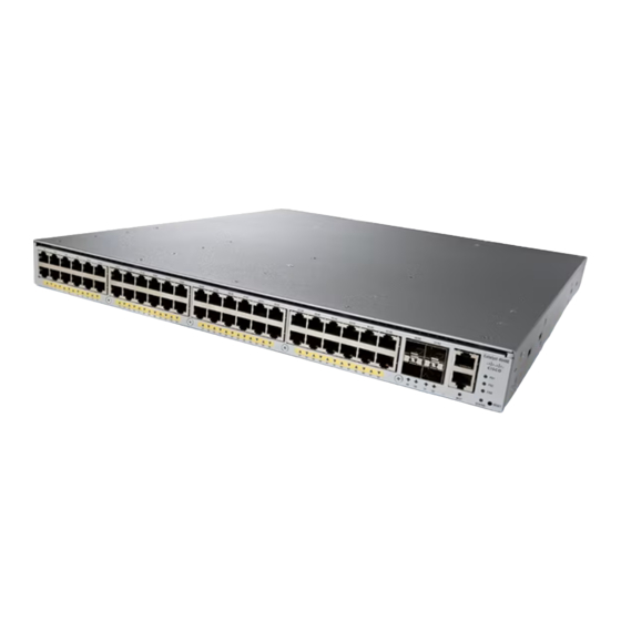
The fan trays and the power supplies are not interchangeable between the Catalyst 4948E and the Catalyst 4948E-F switch chassis. For additional information about the Cisco Catalyst 4948E and the Catalyst 4948E-F switches (including configuration examples and troubleshooting information), see the documents listed on this page: http://www.cisco.com/en/US/products/ps6021/tsd_products_support_series_home.html... - Page 18 Console port Management port The orientation of the Cisco logo shown in Figure 1-1 identifies the chassis as a Catalyst 4948E switch. Note The Cisco logo that appears on the Catalyst 4948E-F chassis top cover is rotated 180 degrees. Additional labels are placed on the Catalyst 4948E-F top cover to denote the direction of the airflow through the chassis.
-
Page 19: Features
Chapter 1 Product Overview Features Figure 1-2 Catalyst 4948E and Catalyst 4948E-F Switches—Rear View of Chassis PW R - 540 100 - 240 7 - 3A 50 - 60 Hz INP UT OU TPU T PW R - 540 100 - 240 7 - 3A 50 - 60 Hz INP UT... - Page 20 Chapter 1 Product Overview Features Table 1-1 Catalyst 4948E and Catalyst 4948E-F Switch Features Feature Description Chassis 1-RU, 48 10/100/1000 ports plus 4 1-GB/10-GB ports, fixed configuration (both chassis) switch with redundant power supplies Uplink ports The chassis has 4 1-GB or 10-GB uplink ports. An SFP or SFP+ transceiver (both chassis) must be installed in the chassis port socket for the port to operate.
- Page 21 Chapter 1 Product Overview Features Table 1-1 Catalyst 4948E and Catalyst 4948E-F Switch Features (continued) Feature Description RESET switch Resets and restarts the switch. • (both chassis) The switch is recessed on chassis front panel and requires a pointed • object to access it.
- Page 22 Chapter 1 Product Overview Features Table 1-1 Catalyst 4948E and Catalyst 4948E-F Switch Features (continued) Feature Description Power supplies Supports one or two power supplies. The following power supplies are • supported: Catalyst 4948E PWR-C49E-300AC-R (300 W AC-input power supply). –...
-
Page 23: Physical And Environmental Specifications
Chapter 1 Product Overview Physical and Environmental Specifications Physical and Environmental Specifications Table 1-2 lists the Catalyst 4948E and Catalyst 4948E-F switch chassis environmental and physical specifications. Table 1-2 Catalyst 4948E and Catalyst 4948E-F Switch Specifications Item Specification Environmental Temperature, operating Certified for operation: 32°... -
Page 24: Fan Tray
Chapter 1 Product Overview Fan Tray Fan Tray Both the Catalyst 4948E and the Catalyst 4948E-F switch chassis have a fan tray that is mounted in the rear of the chassis between the two power supplies. The Catalyst 4948E chassis fan tray (WS-X4993=) provides front-to-back air flow in the chassis and has a front panel that is color-coded dark grey. -
Page 25: Catalyst 4948E-F Fan Tray (Ws-X4993-F=)
Chapter 1 Product Overview Fan Tray Figure 1-3 Catalyst 4948E Fan Tray Backplane connector 12 VDC fan (4X). Air is drawn in from the front of the chassis and exhausted through the rear of the chassis. Captive installation screw (2X) The fan tray draws in air through vents at the front of the chassis and exhausts it through the rear of the chassis as shown in Figure... - Page 26 Chapter 1 Product Overview Fan Tray The WS-X4993-F fan tray is keyed to prevent insertion into the Catalyst 4948E switch chassis. Note Figure 1-5 Catalyst 4948E-F Fan Tray Backplane connector 12 VDC fan (4X). Air is drawn in from the rear of the chassis and exhausted through the front of the chassis.
-
Page 27: Front Panel Leds
Chapter 1 Product Overview Front Panel LEDs Front Panel LEDs A set of LEDs on the chassis front panel provide visual status for the switch. (See Figure 1-7.) Table 1-4 lists the Catalyst 4948E and Catalyst 4948E-F switch chassis front panel LEDs and their meanings. Figure 1-7 Front Panel LEDs PS1 (power supply 1) - Page 28 Chapter 1 Product Overview Front Panel LEDs Catalyst 4948E and Catalyst 4948E-F Switch Installation Guide 1-12 OL-21561-02...
-
Page 29: Chapter 2 Preparing For Installation
Cabling Requirements, page 2-13 • Site Preparation Checklist, page 2-13 • For additional information about the Cisco Catalyst 4948E or the Catalyst 4948E-F switch (including configuration examples and troubleshooting information), see the documents listed on this page: http://www.cisco.com/en/US/products/ps6021/tsd_products_support_series_home.html Safety Safety warnings appear throughout this publication in procedures that may harm you if performed incorrectly. -
Page 30: Site Requirements
Chapter 2 Preparing for Installation Site Requirements Voltages that present a shock hazard may exist on Power over Ethernet (PoE) circuits if Warning interconnections are made using uninsulated exposed metal contacts, conductors, or terminals. Avoid using such interconnection methods, unless the exposed metal parts are located within a restricted access location and users and service people who are authorized within the restricted access location are made aware of the hazard. -
Page 31: Temperature
Chapter 2 Preparing for Installation Site Requirements – Install heavier equipment in the lower half of the rack to maintain a low center of gravity and prevent the rack from becoming top-heavy and tipping over. – Install the stabilizers before mounting or servicing the switch in the rack (if the rack is provided with stabilizing devices). -
Page 32: Air Flow
Chapter 2 Preparing for Installation Site Requirements • Allow a 2-hour warm-up period to bring the chassis up to normal operating temperature before turning it on for chassis that have been exposed to abnormally cold temperatures. Failure to observe these guidelines can damage internal chassis components. The Catalyst 4948E and the Catalyst 4948E-F switches are equipped with internal air temperature Note sensors that are triggered at 104°F (40°C) generating a minor alarm and at 131°F (55°C) generating a major... -
Page 33: Humidity
Chapter 2 Preparing for Installation Site Requirements • Plan for future growth. Your Catalyst 4948E or Catalyst 4948E-F switches currently installed in an enclosed or partially enclosed rack might meet ambient air temperature and air flow requirements now. However, if you add more chassis or other equipment to the rack, the additional heat generated might cause the ambient air temperature within the rack to exceed 104°F (40°C) and can cause minor alarms. -
Page 34: Corrosion
Chapter 2 Preparing for Installation Site Requirements Corrosion Corrosion of system connectors is a gradual process that can eventually lead to intermittent failures of electrical circuits. The oil from a person’s fingers or prolonged exposure to high temperature or humidity can corrode the gold-plated edge connectors and pin connectors on various components in the system. -
Page 35: Shock And Vibration
Chapter 2 Preparing for Installation Power Source Interruptions If the wires exceed the recommended distances, or if wires pass between buildings, give special consideration to the effect of a lightning strike in your vicinity. The electromagnetic pulse caused by lightning or other high-energy phenomena can easily couple enough energy into unshielded conductors to destroy electronic devices. - Page 36 Chapter 2 Preparing for Installation System Grounding Proper grounding practices ensure that the buildings and the installed equipment within them have low-impedance connections and low-voltage differentials between chassis. When you include NEBS-compliant system grounds, you reduce or prevent shock hazards, greatly reduce the chances of equipment damage due to transients, and substantially reduce the potential for data corruption.
-
Page 37: Maintaining Safety With Electricity
Chapter 2 Preparing for Installation System Grounding Table 2-1 Grounding Practice Guidelines (continued) Environment Electromagnetic Grounding Recommendations Noise Severity Level New commercial building is not Grounding best practices should be followed subject to natural environmental as closely as possible. Electromagnetic noise noise or man-made industrial problems are not anticipated, but installing a noise. -
Page 38: Preventing Electrostatic Discharge Damage
Chapter 2 Preparing for Installation System Grounding • If any of the following conditions occur, contact the Cisco Technical Assistance Center: The power cable or plug is damaged. – An object has fallen into the product. – The product has been exposed to water or other liquids. -
Page 39: Power Requirements
Chapter 2 Preparing for Installation Power Requirements After you install the system ground lug, follow these steps to correctly attach the ESD wrist strap: Attach the ESD wrist strap to bare skin as follows: Step 1 If you are using the ESD wrist strap supplied with the FRUs, open the wrist strap package and unwrap the ESD wrist strap. -
Page 40: Power Connection Guidelines For Ac-Powered Systems
DC (–), and one source DC return (+). The length of the cables depends on your switch location. The cables and the lugs required to attach the source DC cables to the power supply are not available from Cisco Systems. They are available from any commercial cable vendor. •... -
Page 41: Cabling Requirements
We strongly recommend that power cabling runs and other potential noise sources be located as far away Caution as practical from LAN cabling that terminates on Cisco equipment. In situations, where this type of long parallel cable runs exist, which cannot be separated by at least 3.3 feet (1 meter), we recommend that you shield these potential noise sources. - Page 42 Chapter 2 Preparing for Installation Site Preparation Checklist Table 2-2 Site Planning Checklist Task No. Planning Activity Verified By Time Date Space evaluation: • Space and layout • Floor covering Impact and vibration • Lighting • Maintenance access • Environmental evaluation: Ambient temperature •...
-
Page 43: Preparing To Install The Chassis
• Lifting the Chassis Safely, page 3-5 • For additional information about the Cisco Catalyst 4948E and the Catalyst 4948E-F switches (including configuration examples and troubleshooting information), see the documents listed on this page: http://www.cisco.com/en/US/products/ps6021/tsd_products_support_series_home.html Catalyst 4948E and Catalyst 4948E-F Switch Installation Guide... -
Page 44: Chapter 3 Installing The Switch
Chapter 3 Installing the Switch Preparing to Install the Chassis Warnings The installation-applicable warnings are listed below. Warning translations in multiple languages are provided in Appendix D. Refer to the statement number for the translations. Warning To prevent the switch from overheating, do not operate it in an area that exceeds the maximum recommended ambient temperature of 104•F (40•C). - Page 45 Chapter 3 Installing the Switch Preparing to Install the Chassis To prevent bodily injury when mounting or servicing this unit in a rack, you must take special Warning precautions to ensure that the system remains stable. The following guidelines are provided to ensure your safety: •...
-
Page 46: Verifying Package Contents
Carefully remove the chassis and accessory kit from the shipping container, and check each item for damage. If any item is missing or damaged, contact your Cisco representative or reseller for support. Return all packing material to the shipping container, and save it. -
Page 47: Lifting The Chassis Safely
Center rack-mount kit for 23-inch racks. Available for both chassis. Kit includes brackets and screws. The kit is available as a separately orderable option. Installation instructions are contained in a separate installation note available on cisco.com. 69-1303-xx Cable management bracket kit. Kit includes the cable management bracket and screws. -
Page 48: Attaching The Rack-Mount Brackets To The Chassis
Chapter 3 Installing the Switch Rack-Mounting the Chassis Attaching the Rack-Mount Brackets to the Chassis Two rack-mount brackets are included as part of the rack-mount kit (69-2037-xx) supplied with both switch chassis. The rack-mount brackets can be installed either on the front sides of the chassis or on the rear sides of the chassis. -
Page 49: Installing The Chassis In The Rack
Chapter 3 Installing the Switch Rack-Mounting the Chassis Figure 3-1 Installing the Rack-Mount Brackets M4 screws (4 screws per bracket) Rack-mount bracket Installing the Chassis in the Rack To install the chassis in the rack, follow these steps: Step 1 Have one person carefully lift and position the chassis in front of the rack. -
Page 50: Installing The Cable Guide (Optional)
Chapter 3 Installing the Switch Rack-Mounting the Chassis Figure 3-2 (top view) shows how to install a chassis in a rack when the chassis has the Note rack-mount brackets attached at the front of the chassis. Figure 3-2 (bottom view) shows how to install a chassis in a rack when the chassis has the rack-mount brackets attached at the rear of the chassis. -
Page 51: Installing The Catalyst 4948E-F Switch Chassis With The Optional Panduit Air Duct Kit
Chapter 3 Installing the Switch Rack-Mounting the Chassis To install the cable guide, follow these steps: Position the cable guide in front of either the left or right rack-mount bracket. Step 1 Attach the cable guide to either the left or right rack-mount bracket using the single M4 screw provided. Step 2 (See Figure... -
Page 52: Installing The System Ground
Chapter 3 Installing the Switch Installing the System Ground Installing the System Ground The system (NEBS) ground provides additional grounding for EMI shielding requirements and is intended to satisfy the Telcordia Technologies NEBS requirements for supplemental bonding and grounding connections. To connect the system ground, you need the following tools and materials: •... - Page 53 Chapter 3 Installing the Switch Installing the System Ground Figure 3-4 Installing the System Ground PW R - 540 100 - 240 7 - 3A 50 - 60 Hz INP UT OU TPU T PW R - 540 100 - 240 7 - 3A 50 - 60 Hz INP UT...
-
Page 54: Connecting Power To The Switch
Chapter 3 Installing the Switch Connecting Power to the Switch Connecting Power to the Switch This section provides instructions on connecting source power to the chassis. Two procedures are provided: Connecting AC Source Power to the Switch, page 3-12 • Connecting DC Source Power to the Switch, page 3-13 •... -
Page 55: Connecting Dc Source Power To The Switch
If you have only one power supply installed in the chassis, you must cover the empty power supply bay Note with a blank power supply cover (Cisco p/n 800-25264-01). The blank power supply cover maintains EMI shielding and proper air flow through the chassis. - Page 56 Chapter 3 Installing the Switch Connecting Power to the Switch To connect source DC power to the DC-input power supply installed in the Catalyst 4948E switch, follow these steps: Verify that all of the site power and grounding requirements described in “Power Requirements”...
-
Page 57: Attaching The Interface Cables
Chapter 3 Installing the Switch Attaching the Interface Cables Step 9 Do not turn source DC power on at this time. Continue the installation process by attaching the interface cables to the chassis ports. Figure 3-6 Connecting Source DC to the DC-Input Power Supply (PWR-C49-300DC) PW R - C49 -300 DC -48 To -60V... -
Page 58: Connecting To The Downlink Ports
Chapter 3 Installing the Switch Attaching the Interface Cables Connecting to the Downlink Ports Both chassis have 48 10/100/1000 ports. The ports configure themselves to operate at the speed of the attached devices. If the attached devices do not support autonegotiation, you can explicitly set the speed and duplex parameters. - Page 59 Position the SFP transceiver in front of the socket opening. Step 5 Different Cisco devices have different SFP socket configurations. Your Cisco device could have Note either a latch-up or a latch-down orientation. Ensure that you are installing the SFP transceiver in the correct orientation for your Cisco device.
- Page 60 Chapter 3 Installing the Switch Attaching the Interface Cables Figure 3-10 Inserting an SFP Transceiver into a Socket Press the SFP transceiver into the slot firmly with your thumb as shown in Figure 3-11. Step 7 Figure 3-11 Latching the SFP Transceiver To verify that the SFP transceiver is seated and latched properly: Step 8 Grasp the SFP transceiver as shown in...
- Page 61 Step 10 For complete information on inspecting and cleaning fiber-optic connections, see the white-paper document at this URL: http://www.cisco.com/en/US/tech/tk482/tk876/technologies_white_paper09186a0080254eba.shtml Remove the dust plugs from the SFP transceiver optical bores. Step 11 Immediately attach the network interface cable LC connector to the SFP transceiver.
-
Page 62: Connecting To The Ethernet Management Port
Chapter 3 Installing the Switch Attaching the Interface Cables Step 13 To connect 1000BASE-T SFP transceivers to a copper network, follow these substeps: Caution To comply with GR-1089 intrabuilding lightning immunity requirements, you must use grounded, shielded, twisted-pair Category 5 cabling. Insert the Category 5 network cable RJ-45 connector into the SFP transceiver RJ-45 connector. -
Page 63: Powering Up The Switch
Chapter 3 Installing the Switch Powering Up the Switch Powering Up the Switch This section provides a quick power-up procedure for a switch. The section is divided into the following topics: Starting the Terminal-Emulation Software, page 3-21 • Powering Up the Switch, page 3-21 •... - Page 64 Note The POST failures are usually fatal. Call Cisco Systems if your switch does not pass the POST. For information on configuring the Catalyst 4948E or the Catalyst 4948E-F switch, refer to the appropriate software configuration guide at: http://www.cisco.com/en/US/products/ps6021/products_installation_and_configuration_guides_list.ht...
-
Page 65: Warnings
Only trained and qualified personnel should be allowed to install, replace, or service this equipment. Statement 1030 For additional information about the Cisco Catalyst 4948E switch (including configuration examples and troubleshooting information), see the documents listed on this page: http://www.cisco.com/en/US/products/ps6021/tsd_products_support_series_home.html... -
Page 66: Removing And Installing The Dc-Input Power Supply
Chapter 4 Removal and Replacement Procedures Removing and Installing the DC-Input Power Supply Removing and Installing the DC-Input Power Supply This section describes how to remove and install the DC-input power supplies (PWR-C49-300DC) in the Catalyst 4948E switch chassis and contains these subsections: Required Tools, page 4-2 •... - Page 67 Chapter 4 Removal and Replacement Procedures Removing and Installing the DC-Input Power Supply Step 3 Disconnect the DC-input cables from the power supply terminal block in this order (See Figure 4-1, top view): Positive (+) source DC cable from the positive (+) terminal Negative (–) source DC cable from the negative (–) terminal Ground cable from the ground terminal Loosen the captive installation screw on the power supply.
- Page 68 Chapter 4 Removal and Replacement Procedures Removing and Installing the DC-Input Power Supply Figure 4-1 Removing the DC-Input Power Supply PW R - C49 -300 DC -48 To -60V INP UT OU TPU T PW R - C49 -300 DC -48 To -60V INP UT OU TPU T...
-
Page 69: Installing The Dc-Input Power Supply
Chapter 4 Removal and Replacement Procedures Removing and Installing the DC-Input Power Supply Installing the DC-Input Power Supply Before performing any of the following procedures, ensure that power is removed from the DC Warning circuits. To ensure that all power is removed, locate the circuit breakers or fuses on the DC power lines that service the DC circuits. - Page 70 Chapter 4 Removal and Replacement Procedures Removing and Installing the DC-Input Power Supply Step 8 Connect the DC-input wires to the terminal block in this order: Ground cable to the ground connector on the terminal block Negative (–) source DC cable to the negative (–) connector on the terminal block Positive (+) source DC cable to the positive (+) connector on the terminal block After ensuring that all wire connections are secure, reinstall the plastic terminal block cover.
- Page 71 Chapter 4 Removal and Replacement Procedures Removing and Installing the DC-Input Power Supply Figure 4-2 Installing the DC-Input Power Supply PW R - C49 -300 DC -48 To -60V INP UT OU TPU T PW R - C49 -300 DC -48 To -60V INP UT OU TPU T...
-
Page 72: Removing And Installing The Ac-Input Power Supply
Chapter 4 Removal and Replacement Procedures Removing and Installing the AC-Input Power Supply Removing and Installing the AC-Input Power Supply This section describes how to remove and install the AC-input power supply (PWR-C49E-300AC-R) in the Catalyst 4948E switch chassis or the AC-input power supply (PWR-C49E-300AC-F) in the Catalyst 4948E-F switch chassis and contains the following subsections: •... -
Page 73: Installing The Ac-Input Power Supply
Chapter 4 Removal and Replacement Procedures Removing and Installing the AC-Input Power Supply Figure 4-3 Removing and Installing an AC-Input Power Supply PWR - 540 100 - 240 7 - 3A 50 - 60 Hz INPU T OUT PUT PWR - 540 100 - 240 7 - 3A 50 - 60 Hz... -
Page 74: Removing And Installing The Fan Tray
Chapter 4 Removal and Replacement Procedures Removing and Installing the Fan Tray Step 5 Tighten the power supply captive installation screw. Plug the AC power cord appliance connector (C15 or C13 connector) into the AC-in receptacle on the Step 6 power supply. -
Page 75: Installing The Fan Tray
Chapter 4 Removal and Replacement Procedures Removing and Installing the Fan Tray Remove the replacement fan tray from its shipping packaging and place it near the chassis that you are Step 1 working on. Loosen the two captive installation screws on the installed fan tray. Step 2 Grasp the fan assembly handle, and pull it outward;... - Page 76 Chapter 4 Removal and Replacement Procedures Removing and Installing the Fan Tray Catalyst 4948E and Catalyst 4948E-F Switch Installation Guide 4-12 OL-21561-02...
-
Page 77: Appendix
This appendix provides the specifications for the AC-input and DC-input power supplies supported on the Catalyst 4948E switch. For additional information about the Cisco Catalyst 4948E and the Catalyst 4948E-F switches (including configuration examples and troubleshooting information), see the documents listed on this page: http://www.cisco.com/en/US/products/ps6021/tsd_products_support_series_home.html... - Page 78 Appendix A Power Supply Specifications 300 W AC-Input Power Supply (PWR-C49E-300AC-R) Figure A-1 AC-Input Power Supply (PWR-C49E-300AC-R) Features R - C 4 9 E - 3 0 0 A C PWR-C49E-300AC-R AC power switch Power supply LEDs Captive installation screw Power supply handle AC power cord receptacle Catalyst 4948E and Catalyst 4948E-F Switch Installation Guide...
- Page 79 Appendix A Power Supply Specifications 300 W AC-Input Power Supply (PWR-C49E-300AC-R) Table A-1 lists the specifications for the 300 W AC-input power supply (PWR-C49E-300AC-R). Table A-1 300 W AC-Input Power Supply Specifications Item Specification AC-input type • Autoranging input with power factor correction (PFC). •...
- Page 80 Appendix A Power Supply Specifications 300 W AC-Input Power Supply (PWR-C49E-300AC-R) Table A-1 300 W AC-Input Power Supply Specifications (continued) Item Specification Power supply LEDs INPUT OK Green—The INPUT OK LED is lit green when the power • supply has detected that the source AC voltage is within limits. The input voltage is ≥...
-
Page 81: Ac-Input Power Supply (Pwr-C49E-300Ac-F
Appendix A Power Supply Specifications 300 W AC-Input Power Supply (PWR-C49E-300AC-F) Table A-2 PWR-C49E-300AC-R Power Supply Inlet Temperature Versus Fan Speed Fan Speed Inlet Temperature (T) Fan Speed (RPM) Level (± 2°C) (±100RPM) –5°C < T ≤ 35°C 8900 35°C < T ≤ 42°C 9800 42°C <... - Page 82 Appendix A Power Supply Specifications 300 W AC-Input Power Supply (PWR-C49E-300AC-F) Table A-1 lists the specifications for the 300 W AC-input power supply (PWR-C49E-300AC-F). Table A-3 300 W AC-Input Power Supply (PWR-C49E-300AC-F) Specifications Item Specification AC-input type • Autoranging input with power factor correction (PFC). •...
- Page 83 Appendix A Power Supply Specifications 300 W AC-Input Power Supply (PWR-C49E-300AC-F) Table A-3 300 W AC-Input Power Supply (PWR-C49E-300AC-F) Specifications (continued) Item Specification Power supply LEDs INPUT OK Green—The INPUT OK LED is lit green when the power • supply has detected that the source AC voltage is within limits. The input voltage is ≥...
-
Page 84: 300 W Ac-Input Power Supply Power Cords
Appendix A Power Supply Specifications 300 W AC-Input Power Supply Power Cords Table A-4 PWR-C49E-300AC-F Power Supply Inlet Temperature Versus Fan Speed Fan Speed Inlet Temperature (T) Fan Speed (RPM) Level (± 2°C) (±100RPM) –3°C < T ≤ 37°C 8700 37°C <... - Page 85 Appendix A Power Supply Specifications 300 W AC-Input Power Supply Power Cords Figure A-3 CAB-IR2073-C15-AR=, CAB-7KACR= (Argentina) Cordset rating: 10 A, 250 V Length: 8 ft 2 in. (2.5 m) Plug: IRAM 2073 Connector: IEC 60320 C15 Figure A-4 CAB-AS3112-C15-AU=, CAB-7KACA= (Australia and New Zealand) Cordset rating: 10 A, 250 V Plug: SAA AS 3112 Length: 8 ft 2 in.
- Page 86 Appendix A Power Supply Specifications 300 W AC-Input Power Supply Power Cords Figure A-6 CAB-C2316-C15-IT=, CAB-7KACI= (Italy) Cordset rating: 10 A, 250 V Length: 8 ft 2 in. (2.5 m) Plug: CEI 23-16/7 Connector: IEC 60320 C15 Figure A-7 CAB-US515-C15-US=, CAB-7KAC= (North America) Cordset rating 13A, 125V (8.2 feet) (2.5m) Plug:...
- Page 87 Appendix A Power Supply Specifications 300 W AC-Input Power Supply Power Cords Figure A-9 CAB-SABS-C15-IND (South Africa, India) Cordset rating 10A, 250V 8 ft. 0 in (2.4 m) Plug: BS 546 Connector: IEC 60320 C15 (SABS 164-1) Figure A-10 CAB-9K10A-SW=, CAB-7KACSW= (Switzerland) Cordset rating: 10 A, 250 V Length: 8 ft.
-
Page 88: Dc-Input Power Supply (Pwr-C49-300Dc
Appendix A Power Supply Specifications 300 W DC-Input Power Supply (PWR-C49-300DC) 300 W DC-Input Power Supply (PWR-C49-300DC) Figure A-12 shows the 300 W DC-input power supply with the major features identified. The PWR-C49-300DC DC-input power supply is supported only on the Catalyst 4948E switch chassis. Figure A-12 300 W DC-Input Power Supply (PWR-C49-300DC) R - C... - Page 89 Appendix A Power Supply Specifications 300 W DC-Input Power Supply (PWR-C49-300DC) Table A-6 300 W DC-Input Power Supply Specifications (continued) Item Specification Power supply LEDs INPUT OK Green—The INPUT OK LED is lit green when the power • supply has detected that the source DC voltage is within limits. The input voltage is ≥...
- Page 90 Appendix A Power Supply Specifications 300 W DC-Input Power Supply (PWR-C49-300DC) Table A-7 DC-Input Power Supply Inlet Temperature Versus Fan Speed Fan Speed Inlet Temperature (T) Fan Speed (RPM) Level (± 2°C) (±100RPM) –10°C < T ≤ 30°C 5100 30°C < T ≤ 37°C 6400 37°C <...
-
Page 91: Appendix
Ethernet Management Port, page B-12 • Cables and Adapters, page B-12 • For additional information about the Cisco Catalyst 4948E and the Catalyst 4948E-F switches (including configuration examples and troubleshooting information), see the documents listed on this page: http://www.cisco.com/en/US/products/ps6021/tsd_products_support_series_home.html Transceiver Support for Uplink Ports Both the Catalyst 4948E and the Catalyst 4948E-F chassis have four uplink ports that support both 1-GB SFP and 10-GB SFP+ transceivers. - Page 92 Appendix B Transceiver, Chassis Connectors, and Cable and Adapter Specifications Transceiver Support for Uplink Ports Table B-1 1-GB SFP Transceiver Support (continued) Description Transceiver GLC-LH-SM (1000BASE-LH/LX) GLC-ZX-SM (1000BASE-ZX) GLC-BX-D (1000BASE-BX10) GLC-BX-U (1000BASE-BX10) The four uplink ports also support 1-GB CWDM and 1-GB DWDM SFP transceivers, which are described in separate sections.
- Page 93 Appendix B Transceiver, Chassis Connectors, and Cable and Adapter Specifications Transceiver Support for Uplink Ports RJ-45 connector Bail-clasp shown in the open (unlocked) position Bail-clasp shown in the closed (locked) position Catalyst 4948E an Catalyst 4948E-F Switch Installation Guide OL-21561-02...
- Page 94 Appendix B Transceiver, Chassis Connectors, and Cable and Adapter Specifications Transceiver Support for Uplink Ports Table B-2 lists the specifications for the 1000BASE-T and 1000BASE-X SFP transceivers. Table B-2 1000BASE-T and 1000BASE-X SFP Transceiver Specifications SFP Transceiver Interface Nominal Network Fiber Core Modal Cable Distance...
-
Page 95: Cwdm Sfp Transceivers
Storage temperature –40° to 185°F (–40° to 85°C) You can use any combination of SFP modules that your Cisco device supports. The only restrictions are Note that each SFP port must match the wavelength specifications on the other end of the cable and that the cable must not exceed the stipulated cable length for reliable communications. - Page 96 Appendix B Transceiver, Chassis Connectors, and Cable and Adapter Specifications Transceiver Support for Uplink Ports Table B-5 CWDM SFP Transceivers CWDM SFP Transceiver Description Connector Color Code Product Number CWDM-SFP-1470= 1000BASE-CWDM, 1470 nm Gray CWDM-SFP-1490= 1000BASE-CWDM, 1490 nm Violet CWDM-SFP-1510= 1000BASE-CWDM, 1510 nm Blue CWDM-SFP-1530=...
-
Page 97: Dwdm Sfp Transceivers
Appendix B Transceiver, Chassis Connectors, and Cable and Adapter Specifications Transceiver Support for Uplink Ports DWDM SFP Transceivers The four uplink ports on both the Catalyst 4948E and the Catalyst 4948E-F switches also support DWDM SFP transceivers. The DWDM SFP transceiver uses an LC optical connector to connect to single-mode fiber-optic (SMF) cable. - Page 98 Appendix B Transceiver, Chassis Connectors, and Cable and Adapter Specifications Transceiver Support for Uplink Ports Table B-8 DWDM SFP Transceiver Product Numbers, Wavelengths, and ITU Channel Numbers (continued) DWDM SFP Description ITU Channel Product Number DWDM-SFP-3582 1000BASE-DWDM 1535.82 nm SFP DWDM-SFP-3504 1000BASE-DWDM 1535.04 nm SFP DWDM-SFP-3425...
-
Page 99: 10-Gb Sfp+ Transceivers
Appendix B Transceiver, Chassis Connectors, and Cable and Adapter Specifications Transceiver Support for Uplink Ports 10-GB SFP+ Transceivers The Small Form-Factor Pluggable, enhanced (SFP+) 10-Gigabit Ethernet transceiver module is a bidirectional transceiver. It has a 20-pin connector on the electrical interface and a duplex LC connector on the optical interface. - Page 100 Appendix B Transceiver, Chassis Connectors, and Cable and Adapter Specifications Transceiver Support for Uplink Ports When switching from 1-GB SFPs to 10-GB SFP+ transceivers or from an SFP+ to an SFP, the chassis Note recognizes the change in speed and sets the port accordingly. The 10-GB SFP+ transceiver cabling specifications are listed in Table B-11.
-
Page 101: Console Port
Appendix B Transceiver, Chassis Connectors, and Cable and Adapter Specifications Console Port Table B-12 lists the SFP+ transceiver optical transmit and receive specifications. Table B-12 SFP+ Transceiver Module Optical Transmit and Receive Specifications SFP+ Transceiver Transceiver Type Transmit Receive Power (dBm) Transmit and Receive Module Model Power (dBm) -
Page 102: Ethernet Management Port
Appendix B Transceiver, Chassis Connectors, and Cable and Adapter Specifications Ethernet Management Port The two-color LINK LED associated with the console port provides visual status for the port: Green—Link is established • Amber—Administrative disabled • Off—No link is detected • Ethernet Management Port The Ethernet management port supports10/100/1000BASE-T Ethernet. -
Page 103: Rollover Cable Rj-45 To Db-9 Adapter (For Connecting To A Pc
B-5.) If your cable was purchased from Cisco Systems, pin 1 will be white on one connector, and pin 8 will be white on the other. (A rollover cable reverses pins 1 and 8, 2 and 7, 3 and 6, and 4 and 5.) - Page 104 Appendix B Transceiver, Chassis Connectors, and Cable and Adapter Specifications Cables and Adapters Catalyst 4948E an Catalyst 4948E-F Switch Installation Guide B-14 OL-21561-02...
-
Page 105: Appendix
Note For configuration questions or problems, refer to the software configuration guide or the command reference publication. For additional information about the Cisco Catalyst 4948E switch (including configuration examples and troubleshooting information), see the documents listed on this page: http://www.cisco.com/en/US/products/ps6021/tsd_products_support_series_home.html... -
Page 106: Getting Started
If all of these conditions are met and the hardware installation is complete, refer to the Catalyst 4500 Series Switch Cisco IOS Software Configuration Guide and the Catalyst 4500 Series Switch Cisco IOS Command Reference publications to troubleshoot the software. However, if any of these conditions are not met, use the procedures in this chapter to isolate and, if possible, resolve the problem. -
Page 107: Led Readings
Appendix C Troubleshooting the Installation Identifying Startup Problems LED Readings LEDs indicate all system states in the startup sequence. By checking the LEDs, you can determine when and where the system failed in the startup sequence. To check the LEDs, follow these steps: Compare the LED states to those in Table C-1. -
Page 108: Troubleshooting The Power Supply
Appendix C Troubleshooting the Installation Troubleshooting the Power Supply Step 2 Verify that the LEDs on the front panel are lit: The STATUS LED flashes orange during diagnostic boot tests. It is green when the switch is • operational (online). If the system software is unable to start up, this LED stays orange. The port LEDs (1-48 plus the 4 SFP/SFP+ ports) are green when the port is operational (online). -
Page 109: Appendix
Regulations, Chapter 33), page D-43 EMC Class A Notices and Warnings, page D-43 • For additional information about the Cisco Catalyst 4948E and the Catalyst 4948E-F switches (including configuration examples and troubleshooting information), see the documents listed on this page: http://www.cisco.com/en/US/products/ps6021/tsd_products_support_series_home.html... -
Page 110: A P P E N D I X D Regulatory Compliance And Safety Information
Appendix D Regulatory Compliance and Safety Information Translated Safety Warnings Translated Safety Warnings This section repeats in multiple languages the warnings in this guide. Statement 17—Overtemperature Warning To prevent the switch from overheating, do not operate it in an area that exceeds the maximum Warning recommended ambient temperature of 104•F (40•C). -
Page 111: Statement 37-Restricted Area Warning
Appendix D Regulatory Compliance and Safety Information Translated Safety Warnings ¡Advertencia! Para evitar que el interruptor se recaliente, no se debe usar en áreas cuya temperatura ambiente exceda la máxima recomendada, esto es, 40°C (104°F). Para no entorpecer la corriente de aire, dejar por lo menos 7,6 cm (3 pulgadas) de espacio muerto alrededor de la rejilla de ventilación. -
Page 112: Statement 39-Grounded Equipment Warning
Appendix D Regulatory Compliance and Safety Information Translated Safety Warnings ¡Advertencia! Esta unidad ha sido diseñada para instalarse en áreas de acceso restringido. Área de acceso restringido significa un área a la que solamente tiene acceso el personal de servicio mediante la utilización de una herramienta especial, cerradura con llave, o algún otro medio de seguridad, y que está... -
Page 113: Statement 43-Jewelry Removal Warning
Appendix D Regulatory Compliance and Safety Information Translated Safety Warnings Statement 43—Jewelry Removal Warning Before working on equipment that is connected to power lines, remove jewelry (including rings, Warning necklaces, and watches). Metal objects will heat up when connected to power and ground and can cause serious burns or weld the metal object to the terminals. - Page 114 Appendix D Regulatory Compliance and Safety Information Translated Safety Warnings Attention Avant d’accéder à cet équipement connecté aux lignes électriques, ôter tout bijou (anneaux, colliers et montres compris). Lorsqu’ils sont branchés à l’alimentation et reliés à la terre, les objets métalliques chauffent, ce qui peut provoquer des blessures graves ou souder l’objet métallique aux bornes.
- Page 115 Appendix D Regulatory Compliance and Safety Information Translated Safety Warnings Catalyst 4948E and Catalyst 4948E-F Switch Installation Guide OL-21561-02...
-
Page 116: Statement 48-Stacking The Chassis Warning
Appendix D Regulatory Compliance and Safety Information Translated Safety Warnings Statement 48—Stacking the Chassis Warning Warning Do not stack the chassis on any other equipment. If the chassis falls, it can cause severe bodily injury and equipment damage. Waarschuwing Het chassis mag niet op andere apparatuur gestapeld te worden. Als het chassis mocht vallen, kan dit ernstig lichamelijk letsel en beschadiging van de apparatuur veroorzaken. -
Page 117: Statement 171-Ethernet Cable Shielding In Offices
Appendix D Regulatory Compliance and Safety Information Translated Safety Warnings Statement 171—Ethernet Cable Shielding in Offices Warning Ethernet cables must be shielded when used in a central office environment. Waarschuwing Ethernetkabels dienen beveiligd te worden als ze in een centrale kantooromgeving worden gebruikt. -
Page 118: Statement 258-Fan Tray Removal Warning
Appendix D Regulatory Compliance and Safety Information Translated Safety Warnings Statement 258—Fan Tray Removal Warning When removing the fan tray, keep your hands and fingers away from the spinning fan blades. Let the Warning fan blades completely stop before you remove the fan tray. Waarschuwing Houd tijdens het verwijderen van de ventilator de handen en vingers uit de buurt van de draaiende ventilatorschoepen. -
Page 119: Statement 322-Dc Power Off Warning
Appendix D Regulatory Compliance and Safety Information Translated Safety Warnings Statement 322—DC Power Off Warning Warning Before performing any of the following procedures, ensure that power is removed from the DC circuits. To ensure that all power is removed, locate the circuit breakers or fuses on the DC power lines that service the DC circuits. -
Page 120: Statement 1001-Work During Lightning Activity
Appendix D Regulatory Compliance and Safety Information Translated Safety Warnings Advarsel Før du foretar noen av følgende prosedyrer må du påse at strømmen er fjernet fra likestrømkretsene. For å være sikkert på at all strøm er fjernet, finn vernebryterne eller sikringene på likestrømlinjene som går til likestrømkretsene. -
Page 121: Statement 1003-Dc Power Disconnection
Appendix D Regulatory Compliance and Safety Information Translated Safety Warnings Statement 1003—DC Power Disconnection Before performing any of the following procedures, ensure that power is removed from the Warning DC circuit. Waarschuwing Voordat u een van de onderstaande procedures uitvoert, dient u te controleren of de stroom naar het gelijkstroom circuit uitgeschakeld is. - Page 122 Appendix D Regulatory Compliance and Safety Information Translated Safety Warnings Aviso Antes de executar qualquer um dos procedimentos a seguir, verifique se a energia foi removida do circuito DC. Advarsel Før du udfører nogen af følgende procedurer, skal du sikre dig, at der ikke er strøm til jævnstrømskredsløbet.
-
Page 123: Statement 1004-Installation Instructions
Appendix D Regulatory Compliance and Safety Information Translated Safety Warnings Statement 1004—Installation Instructions Warning Read the installation instructions before connecting the system to the power source. Waarschuwing Raadpleeg de installatie-instructies voordat u het systeem op de voedingsbron aansluit. Varoitus Lue asennusohjeet ennen järjestelmän yhdistämistä virtalähteeseen. Attention Avant de brancher le système sur la source d'alimentation, consulter les directives d'installation. -
Page 124: Statement 1006-Chassis Warning For Rack-Mounting And Servicing
Appendix D Regulatory Compliance and Safety Information Translated Safety Warnings Statement 1006—Chassis Warning for Rack-Mounting and Servicing Warning To prevent bodily injury when mounting or servicing this unit in a rack, you must take special precautions to ensure that the system remains stable. The following guidelines are provided to ensure your safety: •... - Page 125 Appendix D Regulatory Compliance and Safety Information Translated Safety Warnings Varoitus Kun laite asetetaan telineeseen tai huolletaan sen ollessa telineessä, on noudatettava erityisiä varotoimia järjestelmän vakavuuden säilyttämiseksi, jotta vältytään loukkaantumiselta. Noudata seuraavia turvallisuusohjeita: • Jos telineessä ei ole muita laitteita, aseta laite telineen alaosaan. •...
- Page 126 Appendix D Regulatory Compliance and Safety Information Translated Safety Warnings Aviso Para se prevenir contra danos corporais ao montar ou reparar esta unidade numa estante, deverá tomar precauções especiais para se certificar de que o sistema possui um suporte estável. As seguintes directrizes ajudá-lo-ão a efectuar o seu trabalho com segurança: •...
- Page 127 Appendix D Regulatory Compliance and Safety Information Translated Safety Warnings • • • • • • Aviso Para evitar lesões corporais ao montar ou dar manutenção a esta unidade em um rack, é necessário tomar todas as precauções para garantir a estabilidade do sistema. As seguintes orientações são fornecidas para garantir a sua segurança: •...
- Page 128 Appendix D Regulatory Compliance and Safety Information Translated Safety Warnings Catalyst 4948E and Catalyst 4948E-F Switch Installation Guide D-20 OL-21561-02...
- Page 129 Appendix D Regulatory Compliance and Safety Information Translated Safety Warnings Catalyst 4948E and Catalyst 4948E-F Switch Installation Guide D-21 OL-21561-02...
-
Page 130: Statement 1008-Class 1 Laser Product
Appendix D Regulatory Compliance and Safety Information Translated Safety Warnings Statement 1008—Class 1 Laser Product Warning Class 1 laser product. Waarschuwing Klasse-1 laser produkt. Varoitus Luokan 1 lasertuote. Attention Produit laser de classe 1. Warnung Laserprodukt der Klasse 1. Avvertenza Prodotto laser di Classe 1. -
Page 131: Statement 1017-Restricted Area
Appendix D Regulatory Compliance and Safety Information Translated Safety Warnings Statement 1017—Restricted Area This unit is intended for installation in restricted access areas. A restricted access area can be Warning accessed only through the use of a special tool, lock and key, or other means of security. Waarschuwing Deze eenheid is bestemd voor installatie in plaatsen met beperkte toegang. - Page 132 Appendix D Regulatory Compliance and Safety Information Translated Safety Warnings ¡Advertencia! Esta unidad ha sido diseñada para instalación en áreas de acceso restringido. Sólo puede obtenerse acceso a una de estas áreas mediante la utilización de una herramienta especial, cerradura con llave u otro medio de seguridad.
-
Page 133: Statement 1019-Main Disconnecting Device
Appendix D Regulatory Compliance and Safety Information Translated Safety Warnings Statement 1019—Main Disconnecting Device The plug-socket combination must be accessible at all times, because it Warning serves as the main disconnecting device. Waarschuwing De combinatie van de stekker en het elektrisch contactpunt moet te allen tijde toegankelijk zijn omdat deze het hoofdmechanisme vormt voor verbreking van de aansluiting. -
Page 134: Statement 1030-Equipment Installation
Appendix D Regulatory Compliance and Safety Information Translated Safety Warnings Advarsel Kombinasjonen støpsel/uttak må alltid være tilgjengelig ettersom den fungerer som hovedfrakoplingsenhet. Aviso A combinação ficha-tomada deverá ser sempre acessível, porque funciona como interruptor principal. ¡Advertencia! El conjunto de clavija y toma ha de encontrarse siempre accesible ya que hace las veces de dispositivo de desconexión principal. - Page 135 Appendix D Regulatory Compliance and Safety Information Translated Safety Warnings Advarsel Bare opplært og kvalifisert personell skal foreta installasjoner, utskiftninger eller service på dette utstyret. Aviso Apenas pessoal treinado e qualificado deve ser autorizado a instalar, substituir ou fazer a revisão deste equipamento.
-
Page 136: Statement 1040-Product Disposal
Appendix D Regulatory Compliance and Safety Information Translated Safety Warnings Statement 1040—Product Disposal Ultimate disposal of this product should be handled according to all national laws and regulations. Warning Waarschuwing Het uiteindelijke wegruimen van dit product dient te geschieden in overeenstemming met alle nationale wetten en reglementen. - Page 137 Appendix D Regulatory Compliance and Safety Information Translated Safety Warnings Aviso O descarte definitivo deste produto deve estar de acordo com todas as leis e regulamentações nacionais. Advarsel Endelig bortskaffelse af dette produkt skal ske i henhold til gældende love og regler. Catalyst 4948E and Catalyst 4948E-F Switch Installation Guide D-29 OL-21561-02...
-
Page 138: Statement 1045-Short-Circuit Protection
Appendix D Regulatory Compliance and Safety Information Translated Safety Warnings Statement 1045—Short-circuit Protection Warning This product requires short-circuit (overcurrent) protection, to be provided as part of the building installation. Install only in accordance with national and local wiring regulations. Waarschuwing Voor dit product moet kortsluitbeveiliging (overstroombeveiliging) deel uitmaken van de installatie in het gebouw. - Page 139 Appendix D Regulatory Compliance and Safety Information Translated Safety Warnings Aviso Este produto requer uma proteção contra curto-circuito (sobrecorrente) que deve fazer parte da instalação do edifício. Faça a instalação somente de acordo com as regulamentações de cabeamento nacionais e locais. Advarsel Dette produkt kræver beskyttelse mod kortslutning (overstrøm).
-
Page 140: Statement 1046-Installing Or Replacing The Unit
Appendix D Regulatory Compliance and Safety Information Translated Safety Warnings Statement 1046—Installing or Replacing the Unit Warning When installing or replacing the unit, the ground connection must always be made first and disconnected last. Waarschuwing Bij installatie of vervanging van het toestel moet de aardverbinding altijd het eerste worden gemaakt en het laatste worden losgemaakt. -
Page 141: Statement 1051-Laser Radiation
Appendix D Regulatory Compliance and Safety Information Translated Safety Warnings Advarsel Ved installation og genmontering af enheden, skal jordforbindelsen altid installeres først og afinstalleres sidst. Statement 1051—Laser Radiation Invisible laser radiation may be emitted from disconnected fibers or connectors. Do not stare into Warning beams or view directly with optical instruments. - Page 142 Appendix D Regulatory Compliance and Safety Information Translated Safety Warnings Attention Les fibres ou connecteurs débranchés risquent d'émettre des rayonnements laser invisibles à l'œil. Ne regardez jamais directement les faisceaux laser à l'œil nu, ni d'ailleurs avec des instruments optiques. Warnung Unterbrochene Fasern oder Steckerverbindungenkönnen unsichtbare Laserstrahlung abgeben.
-
Page 143: Statement 1072-Shock Hazard From Interconnections
Appendix D Regulatory Compliance and Safety Information Translated Safety Warnings Statement 1072—Shock Hazard from Interconnections Voltages that present a shock hazard may exist on Power over Ethernet (PoE) circuits if Warning interconnections are made using uninsulated exposed metal contacts, conductors, or terminals. Avoid using such interconnection methods, unless the exposed metal parts are located within a restricted access location and users and service people who are authorized within the restricted access location are made aware of the hazard. - Page 144 Appendix D Regulatory Compliance and Safety Information Translated Safety Warnings Varoitus Sisäisissä Ethernet (PoE) -virtapiireissä voi olla sähköiskun vaaran aiheuttavia jännitteitä, jos kytkentöihin käytetään eristämättömiä paljaita metalliliittimiä tai -johtimia. Vältä tällaisia kytkentöjä, elleivät paljaat metalliosat ole rajatussa paikassa. Ilmoita valtuutetuille käyttäjille ja huoltohenkilöille vaarasta.
-
Page 145: Statement 1074-Comply With Local And National Electrical Codes
Appendix D Regulatory Compliance and Safety Information Translated Safety Warnings Varning! Det kan finnas spänningar på PoE-kretsarna (Power over Ethernet) som utgör risk för stötar om sammankopplingarna görs med ej isolerade, exponerade kontakter, ledare och/eller terminaler av metall. Undvik att använda sådana sammankopplingsmetoder, såvida inte de exponerade metalldelarna finns i en plats med begränsad åtkomst. - Page 146 Appendix D Regulatory Compliance and Safety Information Translated Safety Warnings Varoitus Laitteisto tulee asentaa paikallisten ja kansallisten sähkömääräysten mukaisesti. Attention L'équipement doit être installé conformément aux normes électriques nationales et locales. Warnung Die Installation der Geräte muss den Sicherheitsstandards entsprechen. Avvertenza L'installazione dell'impianto deve essere conforme ai codici elettrici locali e nazionali.
-
Page 147: Statement 1075-Hazardous Voltage Or Energy Present On Dc Power Terminals
Appendix D Regulatory Compliance and Safety Information Translated Safety Warnings Statement 1075—Hazardous Voltage or Energy Present on DC Power Terminals Warning Hazardous voltage or energy may be present on DC power terminals. Always replace cover when terminals are not in service. Be sure uninsulated conductors are not accessible when cover is in place. -
Page 148: Regulatory Standards Compliance
Appendix D Regulatory Compliance and Safety Information Regulatory Standards Compliance Regulatory Standards Compliance This section includes all regulatory, safety, EMC (Class A or Class B), telecomm, and NEBS standards. The Catalyst 4948E and the Catalyst 4948E-F switches are in compliance with national and international standards as described in Table D-1. - Page 149 EN300386 KN24 For specific details about the years, revisions, and relevant amendments, refer to the applicable declaration of conformity available at http://www.cisco.com. The Catalyst 4948E and the Catalyst 4948E-F switches meets the industry EMC, safety, and environmental standards described in Table D-2.
-
Page 150: Gr-1089-Core Issue 3 Documentation Statements
Appendix D Regulatory Compliance and Safety Information GR-1089-CORE Issue 3 Documentation Statements GR-1089-CORE Issue 3 Documentation Statements Statement 7016—GR-1089-Core Intrabuilding Lightning—Immunity Requirements To comply with GR-1089-Core intrabuilding lightning-immunity requirements, you must use shielded Caution (screened) cable that is grounded at both ends. GR-1089-CORE Issue 4 Documentation Statements Statement 7001—ESD Mitigation This equipment may be ESD sensitive. -
Page 151: Statement 7015-Equipment Bonding And Grounding
Appendix D Regulatory Compliance and Safety Information European Directives Statement 7015—Equipment Bonding and Grounding Paint and non-conductive coatings shall be removed before joining the surfaces between the equipment chassis and mounting metalwork. The surfaces shall be cleaned and an anti-oxidant compound applied before joining the surfaces. -
Page 152: Emc Class A Notices And Warnings
Statement 2017—Class A Notice for FCC Modifying the equipment without Cisco’s authorization may result in the equipment no longer complying with FCC requirements for Class A digital devices. In that event, your right to use the equipment may be limited by FCC regulations, and you may be required to correct any interference to radio or television communications at your own expense. -
Page 153: Statement 256-Class A Warning For Hungary
Appendix D Regulatory Compliance and Safety Information EMC Class A Notices and Warnings Statement 256—Class A Warning for Hungary Warning This equipment is a class A product and should be used and installed properly according to the Hungarian EMC Class A requirements (MSZEN55022). Class A equipment is designed for typical commercial establishments for which special conditions of installation and protection distance are used. -
Page 154: Statement 340-Class A Warning For Cispr22
Appendix D Regulatory Compliance and Safety Information EMC Class A Notices and Warnings Statement 340—Class A Warning for CISPR22 Warning This is a class A product. In a domestic environment this product may cause radio interference in which case the user may be required to take adequate measures. Statement 340 Waarschuwing Dit is een product van klasse A. -
Page 155: Statement 371-Power Cable And Ac Adapter
Appendix D Regulatory Compliance and Safety Information EMC Class A Notices and Warnings Statement 371—Power Cable and AC Adapter Catalyst 4948E and Catalyst 4948E-F Switch Installation Guide D-47 OL-21561-02... - Page 156 Appendix D Regulatory Compliance and Safety Information EMC Class A Notices and Warnings Catalyst 4948E and Catalyst 4948E-F Switch Installation Guide D-48 OL-21561-02...
-
Page 157: I N D E X
I N D E X air temperature, ambient Numerics altitude, effects on chassis 19- and 24-inch racks altitude, operating audience, definition accessory kit, contents of AC-input power supplies A-1 to A-11 brackets 300 W power supply features A-2, A-5 cable guide installation AC power cords listing rack-mounting L brackets branch circuit requirements... - Page 158 Index Catalyst 4948E-F switches console port blank power supply cover connecting to 3-20 console port description 1-4, B-10 downlink port LEDs B-11 downlink ports pinout table B-10 Ethernet management port conventions, command fan tray corrosion, sources of fan tray LED customer service power supplies CWDM SFP transceivers...
- Page 159 Index downlink ports fan tray (WS-X4993) connecting interface cables to description 3-16 description fan tray (WS-X4993-F) LEDs description dust and particulates, effects on chassis features, chassis DWDM SFP transceivers front panel LEDs B-6 to B-7 1-11 optical specifications physical and environmental specifications product numbers and ITU channel numbers grounding.
- Page 160 Index power supply power source interruptions, effects on chassis uplink ports power supplies LINK LED AC-input power supplies installation procedure 1-11 AC-input power supplies removal procedure DC-input power supplies removal and replacement procedure DC power cable leads color coding 2-12 management port pinout B-11 LEDs...
- Page 161 Index startup sequence STATUS LED 1-11 safety storage translated safety warnings storage temperature, chassis safety, lifting the chassis syntax, command safety with electricity system ground serial number, chassis accessory kit 3-10 service requests grounding lug 3-10 SFP+ transceivers B-8 to B-10 ground pad location 3-11 cabling specifications...
- Page 162 Index uplink ports connecting to 3-16 description LEDs transceivers 3-16 UPS, selecting 2-11 warning definition warnings translated safety warnings, installation weight, chassis wrist strap, ESD 2-10 Catalyst 4948E and Catalyst 4948E-F Switch Installation Guide IN-6 OL-21561-02...