
Related Manuals for Honeywell HD-DVR-1004


Summary of Contents for Honeywell HD-DVR-1004
-
Page 1: Digital Video Recorder
© 2011 Honeywell International Inc. All rights reserved. http://www.security.honeywell.com Rev. B HD-DVR-1004 HD-DVR-1008 HD-DVR-1016 Digital Video Recorder Honeywell User Manual... -
Page 3: Table Of Contents
Connecting Video Output ... 19 Connecting Audio Input & Output ... 19 Audio Input ... 19 Audio Output... 20 Alarm Input and Output Connection ... 20 Alarm Input and Output Details ... 21 Alarm Input Port ... 21 Alarm Output Port ... 22 Honeywell... - Page 4 Honeywell RS232 ... 23 RS485 ... 23 USB ... 24 4 Overview of Navigation and Controls ... 25 Login, Logout & Main Menu ... 25 Login ... 25 Main Menu ... 26 Logout ... 27 Auto Resume after Power Failure ... 27 Replace Button Battery ...
- Page 5 Encode ... 66 Schedule ... 68 RS232 ... 68 Network ... 69 Alarm ... 79 Detect ... 79 Pan/Tilt/Zoom ... 79 Display ... 80 Default ... 83 Advanced ... 84 HDD Management ... 85 Abnormity ... 87 Alarm Output ... 88 Honeywell...
- Page 6 Honeywell Manual Record ... 89 Account ... 89 Auto Maintain ... 90 TV Adjust ... 91 Text Overlay ... 91 Information ... 95 HDD Information ... 95 BPS ... 96 Log ... 97 Version ... 98 Online Users ... 99 Shutdown ...
- Page 7 Honeywell 8 Appendix ... 165 HDD Capacity Calculation ... 165 Compatible USB Drive List ... 166...
-
Page 9: Explanation Of Symbols
Do not install the appliance in a confined space, such as bookcase or built-in cabinet. To reduce the risk of fire, do not cover the ventilation of the apparatus with newspapers, tablecloths, curtains, etc. And do not place lighted candles on the apparatus. Honeywell... -
Page 10: Important Safety Instructions
Caution Honeywell shall not be held responsible for the use of this product in violation of current laws and statutes. Important Safety Instructions Read these instructions. - Page 11 11. Only use attachment/accessories specified by the manufacturer. 12. Use only with the cart, stand, tripod, bracket, or table specified by the manufacturer, or sold with the apparatus. When a cart is used, use caution when moving the cart/apparatus combination to avoid injury from tip-over. Honeywell...
-
Page 12: Before You Start
Honeywell 13. Unplug this apparatus during lighting storms or when unused for long 14. Refer 15. To Reduce The Risk Of Fire Or Electric Shock, Do Not Expose This 16. Apparatus shall not be exposed to dripping or splashing and no objects... - Page 13 Read and follow all instructions in the user guide when installing and operating the unit. To reduce the risk of electric shock, do not perform any servicing other than that Caution contained in the operating instructions unless you are qualified to do so. Honeywell...
-
Page 15: Features And Specifications
1 Features and Specifications Overview HD-DVR-1004, HD-DVR-1008 and HD-DVR-1016 are excellent digital video surveillance products. They adopt embedded Linux OS to maintain reliable operation. Popular H.264 compression algorithm and G.711 audio compression technology realize high quality, low bit stream. Unique frame- by-frame play function is suitable for detail analysis. - Page 16 Features and Specifications Supports multi-channel audio and video. Independent hardware codecs encodes and decodes the audio and video signal from each channel to maintain video and audio synchronization. • Provides local backup via USB port for flash disks and portable HDDs IE web client can download the file to local HDD to backup via network.
-
Page 17: Specification
Video Input Video Video Output Video Standard Record Speed Video Partition Monitor Touring HD-DVR-1004 HD-DVR-1008 High-performance industrial embedded micro controller Embedded LINUX Multiplex operations: simultaneous multi-channel recording, multi- channel playback and network operation User-friendly graphical user interface Front panel, USB mouse, remote control... - Page 18 Features and Specifications Resolution (PAL/NTSC) Motion Detection Image Quality Privacy mask OSD in record TV Adjust Channel Lock Live Status OSD Color Configuration Audio Input Audio Audio Output Hard Disk Hard Hard disk Space Consumption PAL/NTSC Real-time monitoring: 704×576/704×480 Playback: 704×576/704×480 (6/7 f/s, ch1 up to 25/30 f/s when other...
- Page 19 Supports USB burner (extension function). Supports network download and backup Remote live view of all channels. DVR configuration through web browser client Upgrade or maintenance via web browser client View alarm information such as external alarm, motion detection and video loss...
- Page 20 Web browser, client-end and specific update tool. Password login protection to guarantee safety User-friendly interface when login. Provide the following options: logout /shutdown/ restart. Authentication when shut down to make sure only authorized users can turn off DVR DC +12V/3.3A 12W (Exclude HDD) 0℃-+55℃ 10%-90% 86kpa-106kpa...
-
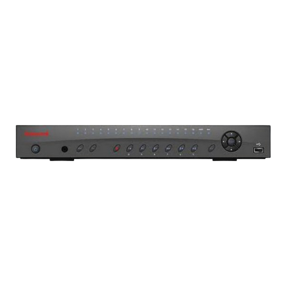
Page 21: Overview And Controls
2 Overview and Controls This section provides information about front panel and rear panel. When you install this series DVR for the first time, please refer to this part first. Front Panel The front panel is shown in Figure 2-1 The Front Panel of HD-DVR-1004/ HD-DVR-1008/ HD-DVR- 1016 Please refer to the following sheet for front panel button information. - Page 22 Overview and Controls Enter Shift Assistant Function Record Play/Pause /5 Reverse/Pause/6 Fast play/7 Slow play/8 Play Next/9 Play previous/0 Go to previous menu, or cancel current operation. During playback, click it to restore real-time monitor mode. Confirm current operation ENTER Go to default button Go to menu In textbox, click this button to switch between numeral,...
-
Page 23: Rear Panel
Record indicator IR Receiver Rear Panel HD-DVR-1004, HD-DVR-1008 and HD-DVR-1016 rear panels are shown as below. See Figure 2-2 The Rear Panel of HD-DVR-1004 Figure 2-3 The Rear Panel of HD-DVR-1008 Figure 2-4 The Rear Panel of HD-DVR-1016 To connect USB storage device, USB mouse. -
Page 24: Connection Diagram
DVR-1004 and HD-DVR-1008’s are similar. Description Video input Audio input Video CVBS output Audio output Network port USB port HDMI port RS232 port Video VGA output Alarm input/alarm output/RS485 port 12VDC Power input port Power button Figure 2-5 for connection diagram of HD-DVR-1016. HD-... -
Page 25: Remote Controller
Honeywell Figure 2-5 Device Connection Remote Controller The remote controller interface is shown as in Figure 2-6. - Page 26 Overview and Controls Figure 2-6 Remote Controller Function Record search Multiple-window switch 0-9 number keys ESC, Cancel Reserved, not effective for HD-DVR-1004, HD-DVR-1008 and HD-DVR-1016 Confirm /menu key Direction keys Auxiliary function key Remote address switch Previous Backward playback Slow play...
-
Page 27: Mouse Control
In real-time monitor mode, you can go to the main menu. When you have selected one menu item, left click the mouse click to view menu content. Implement the control operation. Modify checkbox or motion detection status. Click combo box to bring up the drop down list Honeywell... - Page 28 Overview and Controls Double click mouse In input box, you can select input methods. Left click the corresponding button on the panel where you can input numeral/English character (small/capitalized). Here ← stands for the backspace button. _ stands for the space button. In English input mode: _stands for input a backspace icon and ←...
- Page 29 In numeral input box: Increase or decrease numerical value. Press middle Switch the items in the check box. button Page up or page down Move mouse Selects current control or move control Selects motion detection zone Drag mouse Selects privacy mask zone. Honeywell...
-
Page 30: Installation And Connections
Software CD • USB mouse • Network cable • 12VDC power adapter • Power cord • SATA data cable and screws for HDD installation • User manual • Remote controller • 4 BNC connectors (only in HD-DVR-1004 package) • HDMI cable... -
Page 31: Hdd Installation
HDD Installation This series DVR has only one SATA HDD. Please use HDD of 7200rpm or higher. You can refer to the user guide for a recommended HDD brand. Please follow the instructions below to install the hard disk. 1. Loosen the screws of the upper cover. -
Page 32: Connecting Power Supply
Connecting Power Supply Please check whether the input voltage and device power button match. We recommend you use UPS to guarantee steady operation, DVR life span, and other peripheral equipments’ operation such as cameras. Connecting Video Input and Output Devices Connecting Video Input The video input interface is BNC. -
Page 33: Connecting Video Output
Use the BNC connector to connect the audio channel. Due to high impedance of audio input, please use active sound pick-up. Audio transmission is similar to video transmission. Try to avoid interference, dry joint, and it shall be away from high tension current Honeywell... -
Page 34: Audio Output
Please make sure alarm input mode is grounding alarm input. Grounding signal is needed for alarm input. When you are connecting two DVRs or connecting one DVR and one other device, please use a relay to separate them The alarm output port should not be connected to a high power load directly (It shall be less than 1A) to avoid high current which may result in relay damage. -
Page 35: Alarm Input And Output Details
(ALARM) Figure 3-1 Grounding Alarm Ground line HD-DVR-1004: 1, 2, 3, 4 become valid in low voltage; 5, 6, 7, 8 are not effective. HD-DVR-1008: 1-8 become valid in low voltage. HD-DVR-1016: 1-16 become valid in low voltage. 1-NO C, 2-NO C, 3-NO C Three Normal Open activation outputs. -
Page 36: Alarm Output Port
Installation and Connections Use the same ground with that of DVR if you use external power for the alarm device. Note Figure 3-2 Sample of Alarm Input (Normal Close Type) Alarm Output Port • • Relay Specification: Model JRC-27F Material of the touch... -
Page 37: Rs232
RS232 port is reserved for technical support diagnosis and upgrade. RS485 When the DVR receives a camera control command, it transmits that command up the coaxial cable to the PTZ device. RS485 is a single- direction protocol; the PTZ device cannot return any data to the unit. To enable the operation, connect the PTZ device to the RS485 (A,B) input on the DVR. -
Page 38: Usb
Installation and Connections d “485 A, B” of DVR cannot connect parallel with “485 port” of other device. e. The voltage between of A, B lines of the decoder should be less than 2. Connect the other end of the cable to the proper pins in the connector on the camera. -
Page 39: Overview Of Navigation And Controls
Note From this chapter, most descriptions and figures are based on HD-DVR-1016 operation. Password: admin. (administrator, local and or press Shift on the front panel to For security reasons, please modify the password after your first login. Honeywell Figure 4-1. -
Page 40: Main Menu
Overview of Navigation and Controls Within 30 minutes, login failure three times will result in a system alarm buzz and login failure five times will result in account lock. Figure 4-1 Menu Login Main Menu After you have logged in, the system main menu will appear as shown below. -
Page 41: Logout
The other way is to press the power button on the front panel for at least 3 seconds, causing the system to stop all operations. Then you can click the power button in the rear panel to turn off the DVR. Auto Resume after Power Failure The system can automatically backup video and resume its previous working status after power failure. -
Page 42: Manual Record
Overview of Navigation and Controls Manual Record Live Viewing After you have logged in, the system is in live viewing mode. You can see the system date, time and channel name. If you want to change the system date MenuSettingGeneral). If you want to modify the channel name, refer to the display settings (Main MenuSettingDisplay). - Page 43 You can use the mouse or direction key to highlight the channel number. Figure 4-6. Figure 4-6 Different Status of Manual Record Enable/disable recording in all channels Highlight ○ below All, you can enable all channel recording. • Automatic recording in all channels Highlight “ALL” after “Automatic”. See Honeywell Figure 4-7.
-
Page 44: Stop All Channel Recording
Overview of Navigation and Controls Figure 4-7 Automatic Recording in All Channels • Figure 4-8 Start Manual Record in All Channels Stop all channel recording Please highlight “ALL” after “Closed”. See The system stops all channel recording no matter what mode you have set in the menu (Main menu->Setting->Schedule). -
Page 45: Search & Playback
Usually there are three file types: • R: Regular recording file. • A: External alarm recording file. • M: Motion detection recording file There are several playback windows. Usually the system supports 1/2/3/4-ch playback, and HD-DVR-1016 also supports 16-ch playback. 4-10. Honeywell... - Page 46 Overview of Navigation and Controls Figure 4-10 Record Search Menu Please refer to the following chart for more information. Serial Number Function Play Backward Stop Slow play Fast play Previous frame Next frame Volume Previous file Next channel Next file Previous channel...
-
Page 47: Basic Operation
By selecting the file name and double click the mouse (or click the enter button), you can view the file content. There’re two playback mode, FOUR and ALL in HD-DVR-1016. In FOUR- channel mode, video records of any 1-4 channels can be played simultaneously;... -
Page 48: Calendar
Overview of Navigation and Controls Slow play button ► Play/Pause ►/ Previous/next Backward playback and frame by frame playback Button Backward play: interface. Manual playback frame by frame. Note Calendar Click the calendar icon reference. The highlighted date means there are record files for that day. You can click the blue date to view the file list. -
Page 49: Schedule
Please refer to • Record types: There are four types: regular, motion detection (MD), alarm, motion detection and alarm. Regular: The device will record in the selected time. Figure 4-12 Channel: Please select the channel number first. Redundancy for more details. Honeywell... -
Page 50: Quick Setup
Overview of Navigation and Controls MD: In the selected time, the device will record when MD happens, like motion diction, video loss, video mask. Alarm: In the selected time, the device will record when there is alarm input. MD & Alarm: In the selected time, the device will record when MD happens and at the same time there’s alarm input. -
Page 51: Snapshot
In Encode interface, click snapshot button to input snapshot mode, size, quality and frequency. In General interface please input upload interval. In Schedule interface, please enable snapshot function. At least one read-write disk is required for DVR to record video. Honeywell... - Page 52 Overview of Navigation and Controls Please refer to the following figure for detailed information. Figure 4-13 Schedule Snapshot Setting...
- Page 53 In General interface please input upload interval. • In Detect interface please enable snapshot function for specified channels. Or in alarm interface please enable snapshot function for specified channels. Please refer to the following figure for detailed information. Figure 4-14 Activation Snapshot Setting Honeywell...
- Page 54 Overview of Navigation and Controls Priority Please note the activation snapshot has the higher priority than schedule snapshot. If you have enabled these two types at the same...
-
Page 55: Image Ftp
Record Channel: Select the channel to activate the recording function once the alarm has sounded. Please make sure you have set the MD recording in the schedule interface (Main MenuSettingSchedule) and automatic recording in manual record interface (Main Menu- >Advanced->Manual Record) Honeywell Figure 4-15. - Page 56 Overview of Navigation and Controls • • • • • • • • • Note Check boxes to select the corresponding function. After all the settings, click Save, and the system will return to the previous menu. Note Delay: When detected motion is completed, the system will continue alarm output and recording for a specified time respectively.
- Page 57 Honeywell Figure 4-15 Motion Detection Menu Figure 4-16 Motion Detection Zone Setting...
- Page 58 Overview of Navigation and Controls Figure 4-17 PTZ Activation Setting Figure 4-18 Armed Period Setting...
-
Page 59: Video Loss
Honeywell Figure 4-19 Business Day and Non-Business Day Setting Video Loss Figure 4-15, select “Video Loss” from the type list. You can see the interface is shown in Figure 4-20. This function allows you to be informed when video loss has occurred. You can enable the alarm output channel and enable the show message function. -
Page 60: Camera Masking
Overview of Navigation and Controls Figure 4-20 Menu of Video Loss Camera Masking When someone viciously masks the camera lens, the system can alert you to guarantee video continuity. Camera masking interface is shown as in Figure Tips: You can enable preset/tour/pattern activation operation when video loss occurs. -
Page 61: Alarm Setup And Alarm Activation
• Alarm in: Allows you to select alarm input channel number. • Event type: Select local input. Network input is not effective in HD- DVR-1004, HD-DVR-1008 and HD-DVR-1016. • Type: Normally open or normally closed. Figure 4-22. Figure Honeywell 4-22. - Page 62 Overview of Navigation and Controls • • • • • • • • Note Check boxes to select the corresponding function. After completing all the settings, click Save, and the system goes back to the previous menu. PTZ activation: Here you can set PTZ movement when the alarm occurs.
- Page 63 Honeywell Figure 4-22 Menu of the Alarm Figure 4-23 The settings of PTZ Activation...
-
Page 64: Backup
Figure 4-25 The Settings of Business Days and Non-Business Days Backup DVR supports various backup devices such as CD-RW, DVD driver, USB backup and network download. The records can be played with PC by the Record Player contained in the CD. Here we introduce USB backup first. -
Page 65: Detect Device
Click Start, and you can back up the selected files. There is a process bar for your reference. The USB Flash Disk models listed in Appendix B are strongly recommended, models from other brands may not be fully compatible. Figure 4-27. Honeywell Figure 4-26. Here... - Page 66 Overview of Navigation and Controls When the system completes backup, you can see a dialogue box prompting successful backup. Figure 4-27 Backup Menu with Search Results Click Start, and the system will begin the burning process. At the same time, the Start button will change to the Stop button. You can view the remaining time and process bar at the bottom left.
-
Page 67: Ptz Control And Color Setup
Please follow the procedures below to go on cable connection • Connect the dome RS485 port to DVR 485 port. • Connect the dome video output cable to DVR video input port. • Connect the power adapter to the dome. name... -
Page 68: Ptz Setup
Overview of Navigation and Controls PTZ Setup Note Boot up the DVR, and input the user name and password. In the main menu, select SettingPan/Tilt/Zoom. The interface is shown as in • • • • • • • The camera video should be in the current screen. - Page 69 Honeywell Figure 4-29 PTZ Setup Menu After completing all the settings click Save. In the single window display (View 1) mode, right-click to open the interface shown in Figure 4-30 (by clicking Fn in the front panel or in the remote controller will cause a menu to appear with only Pan/Tilt/Zoom and Color Setting options).
-
Page 70: Ptz Trace
Overview of Navigation and Controls • • • • Click the buttons Note Figure 4-31 PTZ Control Menu PTZ Trace Please make sure your protocol supports this function. You will need to use a mouse.. Click PTZ Trace in window display. Drag the mouse in the screen to automatically activate Pan and Tilt function, and control the scroll wheel on the mouse to zoom in/out. -
Page 71: Preset/Tour/Pattern/Scan Operations
Here you can activate the following functions: • Preset • Tour • Pattern • Auto scan • Auto pan 4-31, click Set. The interface is shown as below. See 4-31, click Page Switch. The interface is shown in Honeywell Figure 4-32. Figure 4-33. -
Page 72: Preset Setup
Overview of Navigation and Controls Figure 4-33 Function Menu Note Preset Setup Figure position. Figure save the preset. Now you can add this preset to one tour. • Preset, tour and pattern all need the value to be the control parameter. You can define it as you require. •... -
Page 73: Activate Preset
(tour). For each patrol (tour), you can input 80 presets at most. Figure 4-35 Tour Setup 4-33, input the preset number in the “No.” field, and click Preset. 4-32, click Patrol. The interface is shown in Honeywell Figure 4-35. Input the... -
Page 74: Activate Patrol (Tour)
Overview of Navigation and Controls Activate Patrol (tour) Figure patrol button. Pattern Setup Figure as in and iris. Go back to operations as pattern 1. Figure 4-36 Pattern Setup Activate Pattern Function Figure Auto Scan Setup Figure Please go to Then please go to Repeat the above procedures to set right limit. -
Page 75: Activate Auto Scan
Honeywell Figure 4-37 Auto Scan Setup Activate Auto Scan Figure 4-33, click Auto Scan, and the system will begin to auto scan. Correspondingly, the Auto Scan button will change to the Stop button. Click Stop to terminate the scan operation. -
Page 76: Understanding Of Menu Operations And Controls
Understanding of Menu Operations and Controls 5 Understanding Menu Operations Controls Menu Tree This series DVR menu tree is shown as below:... - Page 77 Search Information Setting Menu Backup Advanced Shutdown Honeywell HDD Info Version Online Users General Encode Schedule RS232 Network Alarm Detect Pan/ Tilt/Zoom Display Default HDD Management Alarm Output Abnormity Manual Record Account Auto Maintain TV Adjust Text Overlay...
-
Page 78: Main Menu
Understanding of Menu Operations and Controls Main Menu After you have logged in, the system main menu will appear as shown below. See Setting, Backup, Advanced, and Shutdown. Move the cursor to highlight the icon, and then double-click to enter the sub-menu. Figure 5-1 The Main Menu –... - Page 79 1 to 120 minutes. Default value is 60 minutes. The change will take effect in the new record file. • DVR No: When you are using one remote control to control several DVRs, you can give a name to each DVR for your management. •...
-
Page 80: Encode
Understanding of Menu Operations and Controls Figure 5-2 General Setup Menu Figure 5-3 DST Setup Menu (Week) Figure 5-4 DST setup menu (Date) Encode Encode setting includes the following items. See Note that some series do not support extra stream. Figure 5-5. - Page 81 QCIF resolution. C h1 (HD-DVR-1004, ch9 (HD-DVR-1016 only) in D1 resolution can be set up to 25/30 f/s when all the other channels are of CIF. All the other channels in D1 resolution can only be set up to 6/7 f/s.
-
Page 82: Schedule
Understanding of Menu Operations and Controls Figure 5-5 Encode Menu Figure 5-6 Overlay Menu Schedule Refer to RS232 RS232 interface is shown as follows. There are five items. See Schedule Figure 5-7. -
Page 83: Network
• Stop bit:1 • Parity: None After completing all the settings, click Save, and the system will go back to the previous menu. Figure 5-7 The RS232 Setup Menu Network Here you can input network information. See Honeywell Figure 5-8. -
Page 84: Advanced Setup
Understanding of Menu Operations and Controls • • • • • • • After completing all the settings, click Save, and the system will return to the previous menu. Figure 5-8 Network Setup Menu Advanced Setup IP address: Here you can input the IP address. DHCP: It is to activate auto search IP. - Page 85 The list supports a max of 64 IP addresses. Note that after you enable this function, only the IP listed below can access current DVR. If you disable this function, all IP addresses can access the current DVR. Figure 5-10 IP Filter Menu Multiple Cast Here you can set a multiple cast group.
- Page 86 Understanding of Menu Operations and Controls · IP multiple cast group address -224.0.0.0-239.255.255.255 -“D” address space · The higher four-bit of the first byte=”1110” · Reserved local multiple cast group address -224.0.0.0-224.0.0.255 -TTL=1 When sending out telegraph -For example 224.0.0.1 All systems in the sub-net 224.0.0.2 All routers in the sub-net 224.0.0.4 DVMRP router 224.0.0.5 OSPF router...
-
Page 87: Ntp Setup
Click Save, you need to restart to activate your configuration. After rebooting, DVR will connect to the internet automatically. The IP in the PPPoE is the DVR dynamic value. You can access this IP to visit the unit. Figure 5-11 The PPPoE Setup Menu... -
Page 88: Ddns Setup
Understanding of Menu Operations and Controls Beijing (Hong Kong) Tokyo Sydney Hawaii Alaska Pacific Time(P.T) American Mountain Time(M.T) American Central Time(C.T) American Eastern Time(E.T) Atlantic Time Brazil Middle Atlantic Time Figure 5-12 The NTP Setup Menu DDNS Setup DDNS setup interface is shown in You need a PC with fixed IP in the internet and DDNS software running in this PC. - Page 89 Honeywell http://(Domain Name) e.g.: http://site.3322.org) Now you can open the DDNS Server web search page. Figure 5-13 The DDNS Setup Menu Note that the NNDS type includes: CN99 DDNS、NO-IP DDNS、Private DDNS、Dyndns DDNS and sysdns DDNS. The private DDNS function is reserved for integration, and currently is not effective on HD-16DVR-C.
- Page 90 Understanding of Menu Operations and Controls Figure 5-14 The FTP Server Setup Menu You can use a PC or FTP login tool to test setup. FTP://10.10.7.7 For example, you can login user ZHY to and then test whether it can modify or delete the folder or not. See Figure 5-15.
- Page 91 Honeywell Figure 5-16 The FTP Setup Menu Please check the box left to Enable to activate the FTP function. Here you can input the FTP server address, port and remote directory. When the remote directory is null, the system automatically creates folders according to the IP, time and channel.
- Page 92 Sender email address. Input email subject here. Input receiver email address here. Max input three addresses. On a PC with Windows OS in the same LAN of the DVR, open the Windows Command Prompt by entering “cmd” in StartRun and click...
-
Page 93: Alarm
Protocol: Select corresponding PTZ protocol such as PELCOD. • Address: input corresponding PTZ address. • Baud rate: Select baud rate. • Data bit: Select data bit. • Stop bit: Select stop bit. • Parity: There are three choices: none/odd/even. Alarm Setup and Alarm Activation. Figure 5-19. Honeywell... -
Page 94: Display
Channel name: Here you can modify the channel name. System max support 25-digit (The value may vary due to different series). Please note all your modification here only applies to DVR local end. You need to open web or client end to refresh the channel name. - Page 95 • Motion tour and alarm tour type: HD-DVR-1004 supports 1-window tour; HD-DVR-1008 and HD-DVR-1016 support 1/8 window tour. Please check boxes to select the corresponding function. After completing all the setups click Save, and the system will go back to the previous menu.
- Page 96 Understanding of Menu Operations and Controls Figure 5-21 The Channel Name Setup Menu In tour mode, you can see the following interface. On the right corner, right- click the mouse or click Shift, and you can control the tour. There are two buttons: stands for enabling window switch and stands for enabling...
-
Page 97: Default
• Pan/tilt/zoom • Display • Channel name After all the setups please click the save button, the system will go back to the previous menu. Note System language, video format and user accounts cannot be restored to default setup. Honeywell... -
Page 98: Advanced
Understanding of Menu Operations and Controls Figure 5-23 The Default Setup Menu Advanced Select Advanced on the main window and the interface is shown as follows. alarm output, abnormity, manual record, account, auto maintenance, and TV adjust. Figure 5-24. There are seven function keys in total: HDD management,... -
Page 99: Hdd Management
Honeywell Figure 5-24 The Advanced Menu HDD Management Here you can view and implement hard disk management. See Figure 5-25. You can see current HDD type, status, capacity and record time. By selecting items in the dropdown list and click Execute, you can switch HDD mode between read/write and read-only, erase all data in the HDD, or recover errors. - Page 100 Understanding of Menu Operations and Controls Figure 5-25 The HDD Management Setup Menu Click Alarm Set, and the interface is shown as follows. See Figure 5-26 (this interface is just like the abnormity setup). Refer to Abnormity detailed information. Please check boxes to select the corresponding function.
-
Page 101: Abnormity
• Show message: the system will send message to local screen to alert you when alarm occurs. • Send email: the system can send out an email to alert you when the alarm occurs. Honeywell Figure 5-27. -
Page 102: Alarm Output
Understanding of Menu Operations and Controls Figure 5-27 The Sample of No Disk Abnormity Alarm Output Here you can set proper alarm output. Automatic: start the alarm output automatically according to the settings of Detection/Alarm/Abnormity. Manual: manually start the alarm output Closed: manually stop the alarm output Please select the mode of corresponding alarm output, then click OK, and the system will return to the previous menu. -
Page 103: Manual Record
About reusable function: this function allows multiple users use the same account to login. After all the setups please click Save, and the system will return to the previous menu. Manual Record. Honeywell Figure 5-29. to see “.”). SPACE is not... -
Page 104: Auto Maintain
Understanding of Menu Operations and Controls Figure 5-29 The Account Management Menu Auto Maintain Here you can set auto-reboot time and auto-delete old files setup. See Figure You can select proper setup from the dropdown list. After all the setups please Save, and the system will return to the previous menu. -
Page 105: Tv Adjust
Protocol: Please select from the dropdown list. Setting: Click COM setting button, the interface is shown as in RS232 interface. Please refer to RS232. Overlay channel: Please select the channel you want to overlay the card number. Honeywell Figure 5-31. Figure 5-32. - Page 106 Understanding of Menu Operations and Controls Overlay mode: There are two options: preview and encode. Preview means overlay the card number in the local monitor video. Encode means overlay the card number in the record file. Overlay Position: Here you can select the proper overlay position from the dropdown list.
- Page 107 Honeywell Figure 5-33 Text Overlay(Network Type) For the ATM/POS don’t include protocols, the interface is shown in Figure 5-34. Source IP refers to host IP address that sends out information (usually it is the device host.) Destination IP refers to other systems that receive information.
- Page 108 Understanding of Menu Operations and Controls Figure 5-34 ATM/POS Click Data button you can see an interface is shown in Figure 5-35. Here you can set offset value, length, title according to your communication protocol and data package. Figure 5-35 Data Format...
-
Page 109: Information
After system has booted up, if there is any confliction, the system will go to HDD information interface directly. When HDD confliction occurs, you can check whether system time and HDD time are identical or not. If they are not identical, please go to Figure 5-36. Figure 5-37. Honeywell... -
Page 110: Bps
Understanding of Menu Operations and Controls SettingGeneral to adjust system time or go to AdvancedHDD Management to format the problematic HDD and then reboot the DVR. Figure 5-37The HDD Info Menu Tips: Click Fn or left click the mouse button to view the HDD record time and HDD type and time. -
Page 111: Log
Click Page Up or Page Down to view if there are more than ten files. If a USB storage device is connected to the DVR, you can click Backup to save the displayed logs as a text file FileLog.txt in the USB device. -
Page 112: Version
Understanding of Menu Operations and Controls Figure 5-39 The Log Search Menu Version Here you can view some information related to this version. See 5-40. • • • • • Channel Alarm in Alarm out System version: Build Date Figure... -
Page 113: Online Users
Honeywell Figure 5-40 The Version Menu Online Users Here you can manage online users. See Figure 5-41. You can disconnect one user or block one user if you have proper system rights. The max disconnection time during setup is 65535 seconds. -
Page 114: Shutdown
5-42. Logout menu user: log out menu. You need to input password when you login the next time. Restart application: reboot DVR. Shutdown: system shuts down and turns off power. Restart system: system begins rebooting. Switch user: you can use another account to login. - Page 115 Honeywell Figure 5-42 The Shutdown Menu...
-
Page 116: Web Client Operation
• • • Login Open IE and input DVR address in the address column. For example, if your DVR IP is 10.10.3.16, then please input http:// 10.10.3.16 in IE address column. See • All the operations here are based on HD-DVR-1016. - Page 117 A system pop up with warning information will ask you if you want to install webrec.cab control. Please click yes button. If you can’t download the ActiveX file, please modify your settings as follows, enable or prompt all disabled Active X items. See Figure 6-3. Honeywell Input your IP address here. Figure 6-2...
- Page 118 Web Client Operation Figure 6-2 The Internet Options Window...
- Page 119 After installation, the interface is shown as below. See input your user name and password. Default factory name is admin and password is admin. For security reasons, please modify your password after Note you first login. Honeywell Figure 6-4 Please...
- Page 120 Web Client Operation Figure 6-4 The Web Login Window After you logged in, you can see the main window. See This main window can be divided into the following sections. • • • • Figure 6-5 The Window Switch Menu Section 1: There are five function buttons: configuration, search, alarm, about, and log out .
-
Page 121: Real-Time Monitor
On the top left corner, you can view device IP, channel number, and network monitor bit stream. Figure 6-8 Status Information There are six function buttons in the top right corner. See Figure 6-9 Control Setup Section 5 Honeywell Section 3 Section 4 Figure 6-9. - Page 122 6: Close video. Figure 6-10for the main stream and extra stream switch If a DVR user changes channel names locally, manual refresh (F5) of the web page is required to update the channel names in the web client. Figure 6-11...
-
Page 123: Ptz
Honeywell Figure 6-11 Selection Menu of Local Play File Before PTZ operation, make sure you have properly set PTZ protocol. System Config Pan/Tilt/Zoom). (Please refer to Click PTZ, and the interface is shown as in Figure 6-12... -
Page 124: Direction Key And 3D Positioning Key
Web Client Operation Figure 6-12 PTZ Control Menu Direction key and 3D positioning key Figure In the middle of the eight direction keys, there is a 3D intelligent positioning key. When you click the 3D intelligent positioning key, the system goes back to the single screen mode. -
Page 125: Auto Scan
Honeywell Iris close Open Figure 6-12, click the PTZ setup button and you will see the following interface. See Figure 6-13. Figure 6-13 The PTZ Setup Menu Auto Scan Figure 6-13, move the camera to your desired location and then rotate it to left rotation limit and click Left Limit. -
Page 126: Color
Web Client Operation preset value. Click the add button, and you will have set one preset. Auto tour button, and you will have added one preset in the tour. Repeat the above procedures to add more presets in one tour. Assistant You can select the assistant item from the dropdown list. -
Page 127: Picture Path And Record Path
Honeywell Or you can click the default button to use the system default setup. Figure 6-15 The Color Setup Menu Picture Path and Record Path Click “More”, and you can see an interface shown in Figure 6-16. Figure 6-16 The More Setup Menu Click PIC Path, and you can see an interface shown in Figure 6-17. -
Page 128: Configuration
Here you can view device hardware feature and software version information. See Please click OK to reboot. If there’s an administrator (e.g. 888888) logged in DVR local menu, or web user doesn’t have device reboot privilege, DVR won’t be rebooted and a warning message box will be prompted. - Page 129 Honeywell Figure 6-20 Version Information Menu HDD information Here you can view local storage status and network status including, free capacity and total capacity. See Figure 6-21.
- Page 130 Web Client Operation Figure 6-21 HDD Information Menu Here you can view system log. See Figure 6-22.
- Page 131 Honeywell Figure 6-22 Log Information Menu Click Backup, and the interface is shown in Figure 6-23. Figure 6-23 Log Backup Menu...
-
Page 132: System Configuration
Web Client Operation Please refer to the following sheet for log parameter information. Parameter Type Search Clear Backup System Configuration Please click Save to save your current setup. General Setup Here you can set system time, record length, video format, etc. See 6-24. - Page 133 Honeywell Figure 6-24 General Setup Menu Figure 6-25 DST Setup Menu (Date)
- Page 134 Here you can select file size. Default setup is 60 minutes. When you are using one remote control to manage multiple devices, you can give a serial numbers to the device. Display video standard information: PAL/NTSC. Video standard can only be changed in local DVR GUI.
- Page 135 Figure 6-27 The Encode Menu Figure 6-28 The Color Setting Menu Please refer to the following table for detailed information. Parameter Function Channel For selecting a monitor channel. Channel Name Displays current channel name. You can modify it. Honeywell Figure 6-27.
- Page 136 Web Client Operation Parameter Compression Main Stream Extra Stream Audio/Video Resolution Frame Rate Bit Rate Type Quality Bit Rate Recommended Bit Rate Color Setting Cover (privacy mask) Time Title Function H.264 It includes main stream, motion stream and alarm stream. You can select different encoding frame rates form different recorded events.
- Page 137 2, channel 3 and channel 4. Figure 6-29 The Copy To Menu Schedule Here you can set different periods for various days. The maximum is six periods in one day. See Figure Figure 6-29. Figure 6-29. 6-30. Honeywell...
- Page 138 Web Client Operation Figure 6-30 The Schedule Setup Menu Figure 6-31 The Date and Time Setup Menu Please refer to the following sheet for detailed information.
- Page 139 Save. Refresh Click this button to get device latest configuration information. RS232 The RS232 interface is shown in Honeywell , click Set, and you can go to the corresponding Figure 6-30 Figure 6-32.
- Page 140 Web Client Operation Figure 6-32 The RS232 Setup Menu Please refer to the following sheet for detailed information. Parameter RS232 Function Data Bit Stop Bit Baud Bit Parity System default setup • • • • • Function COM 01 Console is for debug and upgrade. Adapter is for system integration and function enhancement The value ranges from 5 to 8.
- Page 141 0 means there is no user can access current device. Input the PPPoE user name and password you get Remote from the IPS (internet service provider) and enable PPPOE Host PPPoE function. Please save current setup and then reboot the device to get the setup activated. Honeywell Figure 6-33.
- Page 142 Web Client Operation Parameter Email The email interface is shown in Figure 6-34 The Email Setup Menu Please refer to the following sheet for detailed information. Parameter SMTP Server Port User Name Password Function Device connects to the internet via PPPoE after reboot.
- Page 143 DDNS function. The private DDNS Server Type protocol means you use your self-defined private protocol to realize DDNS function. Server IP DDNS server IP address Server Port DDNS server port. Domain Name Your self-defined domain name. Honeywell Figure 6-35.
- Page 144 Web Client Operation Parameter User Password Interval The NAS interface is shown as in Figure 6-36 The NAS Setup Menu Please refer to the following sheet for detailed information. Parameter NAS enable Server IP Port User Name Function The user name you input to log in the server. The password you input to log in the server.
- Page 145 Click this button to get device latest configuration Refresh information. The NTP interface is shown in Here you can realize network time synchronization. Please enable current function and then input server IP, port number, time zone and update interval. Honeywell Figure 6-37.
- Page 146 Web Client Operation Figure 6-37 The NTP Setup Menu Alarm Alarm setup interface is shown as in Figure 6-38.
- Page 147 Select date. If you do not, the current setup applies to today only. You can select the all week column to apply it to the whole week. Click OK button, system goes back to alarm setup interface, please click save button to exit. Anti-dither Not effective in current DVR version. Honeywell...
- Page 148 Web Client Operation Parameter Alarm Out Alarm Latch Record Channel Record Latch Send Email Tour activation Copy Save Refresh Detect Analyzes the video. The system enables the motion detection alarm when it detects the motion reaches the specified sensitivity. The detection interface is shown as in Function Enable alarm activation function.
- Page 149 Honeywell Figure 6-39 The Detection Setup Menu Figure 6-40 The Detection Zone Setup Please refer to the following sheet for detailed information.
- Page 150 You can select all week column to apply to the whole week. Click OK, and the system goes back to motion detection interface; please click Save to exit. Not Effective in the current DVR version. There is 3-channel alarm output. Corresponding to motion detection alarm output port (multiple choices) Enable alarm activation function.
- Page 151 PTZ interface is shown in Figure Please note that before operation, you have set the speed dome address, and that you verify that the DVR and speed dome connection is stable. Figure 6-41 The PTZ Setup Menu Honeywell 6-41.
- Page 152 Web Client Operation Please refer to the following sheet for detailed information. Parameter Channel Protocol Address Baud Rate Data Bit Stop bit Parity Save Refresh Default & Backup Default: Restore the factory default settings. You can select corresponding items. Backup: Export current configuration to local PC or import configuration from current PC.
-
Page 153: Advanced
Please note that if you want to use local storage function, your storage device need to support the current function. Function Restore the factory default settings. Export system configuration to the local PC. Import configuration from PC to the system. Honeywell... - Page 154 Web Client Operation Please select the storage device first and then you can see the items on your right become valid. You can check the corresponding item here. See Figure 6-43. Figure 6-43 The HDD Management Menu Please refer to the following sheet for detailed information. Parameter Format Read/write...
- Page 155 Detection/Alarm/Abnormity. Manual Manually start the alarm output. Stop Manually stop the alarm output. Save You can click the Save button after you complete. Refresh Search alarm output status. Record Record control interface is shown in Honeywell Figure 6-45.
- Page 156 Web Client Operation Figure 6-45 The Record Control Menu Please refer to the following chart for detailed information. Parameter Schedule (Auto) Manual Stop Operation here is the same as the one described in refer to this chapter for detailed information. Account Here you can add, remove users or modify passwords.
-
Page 157: Auto Maintenance
Honeywell Figure 6-46 The Account Management Menu Auto Maintenance Here you can select auto reboot and auto delete old file intervals from the dropdown list. See Figure 6-47. - Page 158 Web Client Operation Figure 6-47 The Auto Maintenance Menu Snapshot For Snapshot function, it can support D1/HD1/BCIF/CIF/QCIF.
- Page 159 Channel 2 to channel 8, channel 10 to channel 16 supports CIF/QCIF. You can select from the dropdown list. Here is for Quality you to set video quality. There are six options: 10%、30%、50%、60%、 80%、100%. 100% is the best quality. Honeywell...
- Page 160 The value ranges from 10s to 300s. If you enable this function, the system can send out an email to notify the specified user. The system can display alarm information in the local DVR disables alarm...
-
Page 161: Additional Function
Sniffer, information parse and character Figure 6-51 overlay. The ATM/POS interface is shown in Source IP refers to host IP address that sends out information (usually it is the device host connected to the DVR.) Destination IP refers to other systems that receive information. -
Page 162: Auto Register
Web Client Operation There are total four groups IP. The record channel applies to one group (optional) only. Six frame ID groups verification can guarantee information validity and legal. The start position, length and data can be set according to your protocol and data packet. -
Page 163: Search
Device ID Search Click Search, and you can see an interface shown in Function Enable auto register function. Device management server number. Device management server IP address. Server port number. Device ID in the device management server. Honeywell Figure 6-53. - Page 164 Web Client Operation Please select record playback mode, and then select start time, end time and channel. Then please click the search button, you can see up to 100 corresponding files in the list. Figure 6-53 The Record Search Menu Select the files you want to download and then click Download, and a dialogue box will appear as shown in Figure 6-54.
- Page 165 Honeywell Figure 6-54 The Record Save Menu Now you can see the system begins to download and the Download button changes to the Stop button. You can click it to terminate the current operation. At the bottom of the interface, there is a process bar for your reference. See...
- Page 166 Web Client Operation Figure 6-55 The Record Search Menu (Saving) When the download has completed, you can see a dialogue box shown in Figure 6-56. Please click OK to exit. Figure 6-56 The Message Box after Download Completed Please refer to the following table for detailed information.
- Page 167 In the search result interface, you can select one or more files to download to your local PC. The playback control bar is shown as below. See • Play Honeywell Figure 6-56 Figure 6-57 Figure 6-57.
-
Page 168: Alarm
Web Client Operation • Pause • Stop • Slow play • Fast play The IP address of playback device and channel number. Alarm Click alarm function, and you can see an interface as shown in Here you can set device alarm type and alarm sound setup. Figure 6-57 The Playback Menu Playback control bar Figure... - Page 169 Disk error Video mask External alarm Listen alarm Operation Video pop-up Prompt Honeywell Function System alarms when video loss occurs. System alarms when motion detection alarm occurs, System alarms when disk is full. System alarms when disk error occurs. Camera mask.
-
Page 170: About
Web Client Operation About Click About, and you can view the current web client information. See Figure Figure 6-59 The Web Client Information Log out Click Log out, and the system goes back to log in interface. See You need to input user name and password to login again. System sends out alarm sound when alarm Sound pop-up occurs. -
Page 171: Un-Install Web Control
Figure 6-60 The Logout Interface Un-install Web Control You can use web un-install tool “uninstall webrec.bat” in the CD to un-install web control. Note Before un-installation, please close all web pages, otherwise the un-installation might result in error. Honeywell... -
Page 172: Faq
7 FAQ 1. DVR cannot boot up properly. 2. DVR often automatically shuts down or stops running. 3. System can not detect hard disk. There are the following possibilities: • Input power is incorrect. • Power connection is incorrect. •... - Page 173 When using BNC output, NTSC and PAL setup is not correct. The real-time video becomes black and white. • DVR and monitor resistance is not compatible. • Video transmission distance is too long or video signal is too much degraded.
- Page 174 10. Time display is not correct. 11. DVR cannot control PTZ. • Program read error, bit data is too small. There is a mosaic displayed on the full screen. Please restart the DVR to solve this problem. • HDD data ribbon error.
- Page 175 • For Windows 98 or Windows ME user, please update your system to Windows 2000 sp4. You can also install client-end software of a previous version. Please note right now, our DVR is not compatible with Windows VISTA control. •...
- Page 176 17. Keyboard cannot control DVR. 18. Alarm signal cannot been disarmed. • There is multiple-cast group setup in DVR. This mode can result in a mosaic appearance. Usually we do not recommend this mode. • There is privacy mask or channel protection setup.
- Page 177 Distance is too far or control angle is too small. • Remote control battery power is low. • Remote control is damaged or DVR front panel is damaged. 21. Record storage period is insufficient. There are the following possibilities: •...
- Page 178 23. Forgot local menu operation password or network password Please contact your local service engineer or our sales person for help. We can guide you to solve this problem. Slight difference may be found in user interface. All the designs and software here are subject to change without prior written notice.
-
Page 179: Appendix
8 Appendix HDD Capacity Calculation Calculate total capacity needed by each DVR according to video recording (video recording type and video file storage time). 1. According to formula (1), calculate storage capacity 2. After video time requirement is confirmed, use Formula (2) to 3. -
Page 180: Compatible Usb Drive List
∑ ×a% In the formula:a% means alarm occurrence rate. Please upgrade the DVR firmware to the latest version to ensure the accuracy of the table below. If you use the USB drive, please confirm the format FAT or FAT32. Model... - Page 182 Honeywell Security Asia Pacific 35F Tower A, City Center, 100 Zun Yi Road, Shanghai 200051, China TEL +86 21 22196888 Honeywell Security (China) Co., Ltd. Block 28, Section 2 Huai De Cui Gang Industrial Estate Fu Yong, Bao An, Shenzhen, P.R.China TEL +86 0755 27326500 ©...