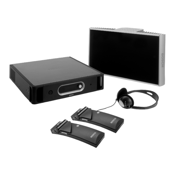
Bosch INTEGRUS Installation And Operating Manual
Digital infra-red language distribution system
Hide thumbs
Also See for INTEGRUS:
- Operation manual (94 pages) ,
- Installation and operation manual (90 pages) ,
- User manual (72 pages)

Related Manuals for Bosch INTEGRUS


Summary of Contents for Bosch INTEGRUS
- Page 1 INTEGRUS DIGITAL INFRA-RED LANGUAGE DISTRIBUTION SYSTEM Installation and Operating Manual BOSCH...
- Page 2 | en INTEGRUS | Digital Infra-red Language Distribution System © 2003 BOSCH Security Systems GmbH BOSCH Security Systems B.V.| February 2003...
-
Page 3: Table Of Contents
1.3.4 Objects, surfaces and reflections ............................... 10 1.3.5 Positioning the radiators ................................11 1.3.6 Overlapping footprints and multipath effects......................... 13 1.4 Planning an Integrus infra-red radiation system ..........................13 1.4.1 Rectangular footprints................................. 13 1.4.2 Planning radiators..................................14 1.4.3 Cabling 15 1.5 Setting the radiator delay switches................................ - Page 4 | en INTEGRUS | Digital Infra-red Language Distribution System 2.5.10 Set channel names ..................................39 2.5.11 Disable or enable carriers................................40 2.5.12 View carrier assignments................................40 2.5.13 Configure auxiliary inputs ................................41 2.5.14 Set sensitivity of the inputs................................. 41 2.5.15 Choose transmitter name................................41 2.5.16 Enable / disable IR-monitoring ..............................
-
Page 5: System Description And Planning
1 System description and planning 1.1 System overview Integrus is a system for wireless distribution of audio signals via infra-red radiation. It can be used in a simultaneous interpretation system for international conferences where multiple languages are used. To enable all participants to understand the proceedings, interpreters simultaneously translate the speaker’s language as required. - Page 6 | en INTEGRUS | Digital Infra-red Language Distribution System Infra-red receivers Two multi-channel infra-red receivers are available: LBB 4540/04 for 4 audio channels LBB 4540/32 for 32 audio channels They can operate with a rechargeable NiMH battery pack or with disposable batteries. Charging circuitry is incorporated in the receiver.
-
Page 7: System Technology
IR radiation The Integrus system is based on transmission by modulated infra-red radiation. Infra-red radiation forms part of the electro- magnetic spectrum, which is composed of visible light, radio waves and other types of radiation. It has a wavelength just above that of visible light. -
Page 8: Quality Modes
Carriers and channels The Integrus system can transmit up to 8 different carrier signals (depending on the transmitter type). Each carrier can contain up to 4 different audio channels. The maximum number of channels per carrier is dependent on the selected quality modes. -
Page 9: Aspects Of Infra-Red Distribution Systems
INTEGRUS | Digital Infra-red Language Distribution System en | 1.3 Aspects of infra-red distribution systems A good infra-red distribution system ensures that all delegates in a conference venue receive the distributed signals without disturbance. This is achieved by using enough radiators, placed at well planned positions, so that the conference venue is covered with uniform IR-radiation of adequate strength. -
Page 10: Ambient Lighting
The Integrus system is practically immune for the effect of ambient lighting. Fluorescent lamps (with or without electronic ballast or dimming facility), such as TL lamps or energy saving lamps give no problems with the Integrus system. Also sunlight and artificial lighting with incandescent or halogen lamps up to 1000 lux give no problems with the Integrus system. -
Page 11: Positioning The Radiators
INTEGRUS | Digital Infra-red Language Distribution System en | 100% 100% Figure 1.10 The texture of the material determines how much light is reflected and how much is absorbed Problems caused by shadows from walls or furniture can be solved by ensuring that there are sufficient radiators and that they are well positioned, so that a strong enough infra-red field is produced over the whole conference area. - Page 12 | en INTEGRUS | Digital Infra-red Language Distribution System Figure 1.13 Combination of direct and reflected radiation Figure 1.14 Combination of several reflected signals For concentrically arranged conference rooms, centrally placed, angled radiators located high up can cover the area very efficiently.
-
Page 13: Overlapping Footprints And Multipath Effects
INTEGRUS | Digital Infra-red Language Distribution System en | Figure 1.17 Radiator for covering seats beneath a balcony 1.3.6 Overlapping footprints and multipath effects When the footprints of two radiators partly overlap, the total coverage area can be larger than the sum of the two separate footprints. -
Page 14: Planning Radiators
| en INTEGRUS | Digital Infra-red Language Distribution System Figure 1.20 A typical rectangular footprint for a mounting angle of Figure 1.21 A typical rectangular footprint for a mounting angle of 15 G 90 G The guaranteed rectangular footprints for various number of carriers, mounting heights and mounting angles can be found in section 7.6. -
Page 15: Cabling
INTEGRUS | Digital Infra-red Language Distribution System en | 1.4.3 Cabling Signal delay differences can occur due to differences in the cable length from the transmitter to each radiator. In order to minimize the risk of black spots, use equal cable length from transmitter to radiator if possible (see Figure 1.23). -
Page 16: Setting The Radiator Delay Switches
| en INTEGRUS | Digital Infra-red Language Distribution System 1.5 Setting the radiator delay switches As described in section 1.3.6, differences in the delays of the signals picked up by the receiver from two or more radiators can cause black spots as a result of the multi path effect. -
Page 17: Determining Delay Switch Positions By Using A Delay Measuring Tool
INTEGRUS | Digital Infra-red Language Distribution System en | Figure 1.26 System with five radiators and measured cable lengths Table 1.1 Calculation of the cable signal delays Radiator Total cable Cable signal delay Cable sgnal Signal delay Delay switch number... -
Page 18: System With Two Or More Transmitters In One Room
| en INTEGRUS | Digital Infra-red Language Distribution System Figure 1.27 and Table 1.2 illustrate the calculation of the signal delays and the delay switch positions. 84 ns 3 0 ns 237 ns 63 ns 339 ns Figure 1.27 System with five radiators and measured impulse response times Table 1.2 Calculation of the delay switch positions of a system with one transmitter... - Page 19 INTEGRUS | Digital Infra-red Language Distribution System en | Figure 1.28 System with master and slave transmitter in multi purpose room Table 1.3 Calculation of the master-to-slave signal delays Cable length Cable Cable Signal delay Master-to-slave master-slave signal delay signal delay...
-
Page 20: System With More Than 4 Carriers And A Radiator Under A Balcony
| en INTEGRUS | Digital Infra-red Language Distribution System 1.5.3 System with more than 4 carriers and a radiator under a balcony Figure 1.29 illustrates a situation in which a radiation signal delay occurs and which can be compensated for. For systems with more than four carriers, add one delay switch position per 10 meter (33 feet) difference in signal path length to the radiators which are closest to the overlapping coverage area. -
Page 21: Testing The Coverage Area
INTEGRUS | Digital Infra-red Language Distribution System en | 1.6 Testing the coverage area An extensive reception quality test must be done to make sure that the whole area is covered with IR radiation of adequate strength and that there are no black spots. Such a test can be done in two ways: Testing during installation: Check that all radiators are connected and powered up and that no loose cables are connected to a radiator. -
Page 22: Infra-Red Transmitters (Lbb 4502/Xx)
2.1 Description The transmitter is the central element of the Integrus system. It accepts asymmetrical audio sources from a maximum of 32 external channels (dependent on the transmitter type) and can be used with the Digital Congress Network (DCN) conference system or analogue discussion and interpretation systems such as the CCS 800 (with up to 12 interpreters desks), or as a stand- alone system distributing external audio sources. - Page 23 INTEGRUS | Digital Infra-red Language Distribution System en | Figure 2.2 Transmitter, front view Mains on/off switch - After switching the mains on, the transmitter starts up and the display (3) will light-up. Mini IR-radiator – Four IREDs, transmitting the same infra-red signal as the radiator output. This can be used for monitoring purposes.
-
Page 24: Audio Interface Modules
| en INTEGRUS | Digital Infra-red Language Distribution System 2.2 Audio interface modules 2.2.1 DCN Interface Module (LBB 3423/00) A DCN Interface Module is required if the transmitter is to be used with the DCN Conference System. The module must be mounted in the transmitter housing (see section 2.2.2). -
Page 25: Mounting An Interface Module In The Transmitter Housing
INTEGRUS | Digital Infra-red Language Distribution System en | 2.2.2 Mounting an interface module in the transmitter housing : Before opening the transmitter housing, make sure that the mains power and all other connections are disconnected! : ICs and many other electronic components are susceptible to electrostatic discharge (ESD). Take preventive measures when handling the interface modules. - Page 26 | en INTEGRUS | Digital Infra-red Language Distribution System Figure 2.7 Mounting an interface module in the transmitter housing BOSCH Security Systems B.V.| February 2003...
-
Page 27: Connections
INTEGRUS | Digital Infra-red Language Distribution System en | 2.3 Connections This chapter gives an overview of typical system connections using the LBB 4502 transmitter: Connecting the DCN system Connecting other external audio sources Connecting an emergency signal switch Connecting to another transmitter 2.3.1... -
Page 28: Connecting Other External Audio Sources
| en INTEGRUS | Digital Infra-red Language Distribution System 2.3.2 Connecting other external audio sources The transmitter has up to 32 audio inputs (depending on the transmitter type) to interface with external asymmetrical audio sources, such as congress systems from other manufacturers or for music distribution. The audio signals (stereo or mono) are connected to the audio input cinch connectors. -
Page 29: Connecting An Emergency Signal
INTEGRUS | Digital Infra-red Language Distribution System en | 2.3.3 Connecting an emergency signal To use the emergency signal function, a switch (normally-open) must be connected to the emergency switch connector. When the switch is closed, the audio signal on the Aux-Right input is distributed to all output channels, overriding all other audio inputs. -
Page 30: Connecting To Another Transmitter
| en INTEGRUS | Digital Infra-red Language Distribution System 2.3.4 Connecting to another transmitter The transmitter can be operated in slave mode to loop-through the IR radiator signals from a master transmitter. One of the four radiator outputs of the master transmitter is connected with an RG59 cable to the radiator signal loop-through input of the slave transmitter. -
Page 31: Using The Configuration Menu
INTEGRUS | Digital Infra-red Language Distribution System en | 2.4 Using the configuration menu 2.4.1 Overview All configuration and operation options of the transmitter are set via an interactive menu, using a 2x16 character LCD display and a 'turn-and-push’ menu button. -
Page 32: Navigate Through The Menu
| en INTEGRUS | Digital Infra-red Language Distribution System 2.4.2 Navigate through the menu Operating the menu is always a sequence of alternating turns and pushes: Turn the button to: Cycle through the menu items within a menu (the menu item number and title on the first line is blinking). -
Page 33: Examples
INTEGRUS | Digital Infra-red Language Distribution System en | To jump back from a sub-menu to an item of the Main menu: Turn the button to move the cursor to the Main menu item number. Push the button. The item number and title starts blinking. - Page 34 | en INTEGRUS | Digital Infra-red Language Distribution System Example 2: Assign a new user defined name to channel 12. (See also section 2.5.10.) Turn the button to select the 11. Turn to move the cursor to Transmitter 4E Channel 12 'Setup' item (4) in the Main the first dash.
- Page 35 INTEGRUS | Digital Infra-red Language Distribution System en | Example 3: Set channel 11 to transmit a Stereo signal in Premium Quality, using audio inputs 14 (L) and 15 (R) as source. (See also section 2.5.9.) Turn the button to select the 12.
-
Page 36: Configuration And Operation
| en INTEGRUS | Digital Infra-red Language Distribution System 2.5 Configuration and operation The next sections give descriptions of the possible configuration options. Each description is followed by the relevant menu items with detailed information per menu option. The default values (see section ‘Reset all options to factory defaults’) are indicated by an asterix (*) when applicable. -
Page 37: View Fault Status
INTEGRUS | Digital Infra-red Language Distribution System en | 2.5.4 View fault status The fault status of the radiators can be seen in the second screen of the Main menu: Menu Items Value (read only) Description 1 Fault Status Fault: The connected radiators function without problems. -
Page 38: Set Transmission Mode
| en INTEGRUS | Digital Infra-red Language Distribution System 2.5.7 Set transmission mode The Transmission Mode menu item (4A) is used to select which signals will be distributed over the channels. It is also possible to switch all channels off (Standby). -
Page 39: Set Channel Names
INTEGRUS | Digital Infra-red Language Distribution System en | Menu Items Option Description 4C Ch. Quality Quality: Set all channels to mono, standard quality. - All Mono SQ Set all channels to mono, premium quality. - All Mono PQ - All Stereo SQ Set all channels to stereo, standard quality. -
Page 40: Disable Or Enable Carriers
| en INTEGRUS | Digital Infra-red Language Distribution System 2.5.11 Disable or enable carriers Normally the channels are automatically assigned to the available carriers. However, when the reception quality of a specific carrier is not good, that carrier can be disabled manually. The channels are then automatically re-assigned to the next available carriers. -
Page 41: Configure Auxiliary Inputs
INTEGRUS | Digital Infra-red Language Distribution System en | 2.5.13 Configure auxiliary inputs The way the signals on the auxiliary inputs (Aux-.L and Aux.-R) are handled can be set in the Aux. Input Mode menu (4H). When the option 'Stereo' is chosen, the signals on both Aux. inputs are distributed as a stereo signal to all channels. This setting can for instance be used to transmit a music signal during breaks in a conference. -
Page 42: Enable / Disable Ir-Monitoring
| en INTEGRUS | Digital Infra-red Language Distribution System 2.5.16 Enable / disable IR-monitoring The mini IR-radiator at the front of the transmitter can be used for monitoring the IR-signal. When required (e.g. for security reasons) this option can be switched off (menu 4M). -
Page 43: Infra-Red Radiators (Lbb 4511/00 And Lbb 4512/00)
INTEGRUS | Digital Infra-red Language Distribution System en | 3 Infra-red Radiators (LBB 4511/00 and LBB 4512/00) 3.1 Description These units accept the carrier signals generated by the transmitter and emit infra-red radiation carrying up to 32 audio distribution channels. They are connected to one or more of the four HF BNC outputs of the IR transmitter. A maximum of 30 radiators can be connected to each of these outputs by means of loop-through connections. -
Page 44: Radiator Status Indication
| en INTEGRUS | Digital Infra-red Language Distribution System 3.2 Radiator status indication A radiator consists of two IRED panels. Each IRED panel has an amber and a red indicator LED (see Figure 3.2) which show the status of the radiator panel:... - Page 45 INTEGRUS | Digital Infra-red Language Distribution System en | Mounting on a floor stand The top of the floor stand is screwed into the suspension bracket (Figure 3.5). The bracket is supplied with both metric and Whitworth threaded plates, and is therefore compatible with most standard floor stands. For floor stands, the mounting angle can be set at 0°, 15°...
- Page 46 | en INTEGRUS | Digital Infra-red Language Distribution System The radiator (plus suspension bracket) is attached to the wall bracket by sliding the mounting bolt over the slot on the wall bracket and then tightening it (see Figure 3.9). A split pin is then inserted into a small hole in the bolt to stop it from working loose (see inset in Figure 3.9).
-
Page 47: Connecting Radiators To The Transmitter
INTEGRUS | Digital Infra-red Language Distribution System en | 3.4 Connecting radiators to the transmitter The transmitter has four BNC HF Output connectors labelled 1, 2, 3 and 4 on the rear panel. All four outputs are functionally identical. They can each drive up to 30 radiators (LBB 4511 and/or 4512) in a loop-through configuration. The radiators are connected with RG59 cables. -
Page 48: Infra-Red Receivers (Lbb 4540/Xx)
| en INTEGRUS | Digital Infra-red Language Distribution System 4 Infra-Red Receivers (LBB 4540/xx) 4.1 Description Receivers are available for 4 or 32 channels. They can operate with a rechargeable NiMH battery pack or with disposable batteries and have controls for channel selection, volume adjustment and an on/off push button. All receivers have a 3.5 mm (0.14 inch) stereo jack output socket for mono or stereo headphones. -
Page 49: Operation
INTEGRUS | Digital Infra-red Language Distribution System en | 4.2 Operation The receiver cannot operate when no headphone is connected. After connecting the headphone the receiver switches to stand- by mode. Push shortly on the on/off button to switch the receiver on. -
Page 50: Charging Units (Lbb 4560/Xx)
| en INTEGRUS | Digital Infra-red Language Distribution System 5 Charging Units (LBB 4560/xx) 5.1 Description The charging units can recharge up to 56 receivers at once. The charging unit contains the power supply with automatic mains voltage selection. The charging electronics and a charging indicator LED are included in each receiver. The charging circuitry checks if a battery pack is present and controls the charging process. -
Page 51: Wall Mounting The Charging Cabinet
INTEGRUS | Digital Infra-red Language Distribution System en | 5.2 Wall mounting the charging cabinet LBB 4560/50 is suitable for either table-top or wall-mounted use. It can be wall-mounted using 5 mm (0.19 inch) screws, with a head diameter of 9 mm (0.35 inch). The screws and plugs delivered with the LBB 4560/50 are designed to mount the unit on a solid brick or concrete wall. -
Page 52: Troubleshooting
| en INTEGRUS | Digital Infra-red Language Distribution System 6 Troubleshooting In this chapter a simple fault-finding guide is given. This is intended to be used to remedy the consequences of incorrect installation. If more serious faults or problems arise the installer should contact a qualified technician. -
Page 53: Technical Data
INTEGRUS | Digital Infra-red Language Distribution System en | 7 Technical Data 7.1 System Specification Overall system characteristics Conforms to IEC 60914, the international standard for conference systems Conforms to IEC 61603 part 7, the international standard for digital infra-red transmission of audio signals for conference... -
Page 54: Transmitters And Modules
| en INTEGRUS | Digital Infra-red Language Distribution System 7.2 Transmitters and Modules 7.2.1 LBB 4502/xx Infra Red Transmitters Physical Characteristics Mounting Brackets for 19” rack mounting or fixing to a table top Detachable feet for free-standing use on a table top Dimensions (H x W x D) 88 x 483 x 350 mm (35 x 190 x 138 in) for 19”... -
Page 55: Radiators And Accessories
INTEGRUS | Digital Infra-red Language Distribution System en | 7.3 Radiators and Accessories 7.3.1 LBB 4511/00 and LBB 4512/00 Radiators Physical Characteristics Mounting Suspension bracket for direct ceiling mounting Mounting plates for floor stands with M10 and 1/2” Whitworth thread... -
Page 56: Receivers, Battery Packs And Charging Units
| en INTEGRUS | Digital Infra-red Language Distribution System 7.4 Receivers, Battery Packs and Charging Units 7.4.1 LBB 4540 Pocket Receivers Physical Characteristics Dimensions (H x W x D) 155 x 45 x 30 mm (6.1 x 1.8 x 1.2 in) Weight excl. -
Page 57: Connection Details
INTEGRUS | Digital Infra-red Language Distribution System en | 7.5 Connection details 7.5.1 Mains cables Blue Neutral Brown Live Green/Yellow Earth/Ground 7.5.2 Audio cables 3-pole XLR connector (female) Pin1 Earth Pin 2 Signal + Pin 3 Signal - Chinch connector (male) -
Page 58: Guaranteed Rectangular Footprints
| en INTEGRUS | Digital Infra-red Language Distribution System 7.6 Guaranteed rectangular footprints LBB 4511/00 at full power LBB 4512/00 at full power number of mounting mounting area length width offset area length width offset carriers height angle [degrees] 1269... - Page 59 INTEGRUS | Digital Infra-red Language Distribution System en | LBB 4511/00 at full power LBB 4512/00 at full power number of mounting mounting area length width offset area length width offset carriers height angle [feet] [degrees] [feet [feet] [feet] [feet]...
-
Page 60: Product Index
| en INTEGRUS | Digital Infra-red Language Distribution System Product index (Page numbers refer to descriptions.) Transmitters LBB 4502/04 4-channel infra-red transmitter ............................22 LBB 4502/08 8-channel infra-red transmitter ............................22 LBB 4502/16 16-channel infra-red transmitter ............................22 LBB 4502/32 32-channel infra-red transmitter ............................