Bosch DCN Next Generation Installation And Operation Manual
Hide thumbs
Also See for DCN Next Generation:
- Operation manual (290 pages) ,
- Installation & user's instructions (288 pages) ,
- Installation and user instructions manual (158 pages)
Table of Contents
Advertisement
Advertisement
Table of Contents

Related Manuals for Bosch DCN Next Generation


Summary of Contents for Bosch DCN Next Generation
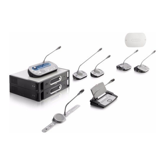
- Page 1 Conference System DCN Next Generation Installation and Operation manual...
-
Page 3: Table Of Contents
DCN-TTH Tabletop Housing 3.25 DCN-FBP panels 3.26 DCN-IDESK Interpreter Desks 3.27 DCN-EPS Extension Power Supply 3.28 LBB4114/00 Trunk Splitter 3.29 LBB4115/00 Tap-off unit 3.30 LBB4116 Extension Cables Bosch Security Systems B.V. Installation and Operation manual DCN-NG_IOM_V4.1 | V1.3 | 2012.07... - Page 4 User set-up 4.6.1 Public areas 4.6.2 Speaking distance 4.6.3 Interpreter booths Device set-up 4.7.1 General 4.7.2 Cables 4.7.3 Temperature 4.7.4 Ventilation 4.7.5 Acoustic feedback Installation 19 inch units DCN-NG_IOM_V4.1 | V1.3 | 2012.07 Installation and Operation manual Bosch Security Systems B.V.
-
Page 5: Conference System Table Of Contents | En
Custom made Optical Network Cables 6.28 Custom made DCN cables Configuration System Configuration 7.1.1 Downloading 7.1.2 Initialization 19 inch units DCN-CCU2 and DCN-CCUB2 Central Control Units LBB4402/00 Audio Expander Bosch Security Systems B.V. Installation and Operation manual DCN-NG_IOM_V4.1 | V1.3 | 2012.07... - Page 6 DCN-CON Concentus Unit DCN-DIS Discussion Unit DCN-WD Wireless Discussion Unit LBB4114/00 or LBB4115/00 Network Splitter PC control software LBB 4402/00 Audio Expander DCN-WAP Wireless Access Point 9.10 DCN-MIC Microphones DCN-NG_IOM_V4.1 | V1.3 | 2012.07 Installation and Operation manual Bosch Security Systems B.V.
-
Page 7: Conference System Table Of Contents | En
DCN-FBP panels 11.2.26 DCN-IDESK Interpreter Desks 11.2.27 DCN-EPS Extension Power Supply 11.2.28 LBB4114/00 Trunk Splitter 11.2.29 LBB4115/00 Tap-off unit 11.2.30 LBB4116 Extension Cables 11.2.31 LBB4416 Optical Network Cables Bosch Security Systems B.V. Installation and Operation manual DCN-NG_IOM_V4.1 | V1.3 | 2012.07... - Page 8 | Table of Contents Conference System 11.2.32 DCN-DDB Data Distribution Board 11.2.33 DCN-IDENC Chip Card Encoder DCN-NG_IOM_V4.1 | V1.3 | 2012.07 Installation and Operation manual Bosch Security Systems B.V.
-
Page 9: Safety
Rules and with RSS-210 of Industry Canada. Operation is subject to the following two conditions: This device may not cause harmful interference. This device must accept any interference received, including interference that may cause undesired operation. Bosch Security Systems B.V. Installation and Operation manual DCN-NG_IOM_V4.1 | V1.3 | 2012.07... - Page 10 | Safety Conference System NOTICE! Changes or modifications made to this equipment, not expressly approved by Bosch Security Systems B.V. may void the FCC authorization to operate this equipment. NOTICE! The Wireless Discussion Units and the Wireless Access Point comply with FCC radiation exposure limits set forth for an uncontrolled environment.
-
Page 11: About This Manual
The sign that is shown along with a note gives more data about the note itself. NOTICE! General sign for notes. NOTICE! Refer to another information source. Bosch Security Systems B.V. Installation and Operation manual DCN-NG_IOM_V4.1 | V1.3 | 2012.07... -
Page 12: Electro-Static Discharges
Conductive floor mat Conductive boots/heel grounding protectors Conductive stool Strap (resistance 0.5 to 1.0 MΩ) Common reference point Conductive bench top Supply ground Table 2.1 ESD prevention DCN-NG_IOM_V4.1 | V1.3 | 2012.07 Installation and Operation manual Bosch Security Systems B.V. -
Page 13: Conversion Tables
Table 2.3 Conversion of units of mass 1 psi = 68.95 hPa 1 hPa = 0.0145 psi Table 2.4 Conversion of units of pressure NOTICE! 1 hPa = 1 mbar. Bosch Security Systems B.V. Installation and Operation manual DCN-NG_IOM_V4.1 | V1.3 | 2012.07... -
Page 14: System Overview
– Installation devices, such as Dual Delegate Interfaces (DDI) and extension power supply units, trunk splitters. NOTICE! Refer to the Integrus manual for all related information. DCN-NG_IOM_V4.1 | V1.3 | 2012.07 Installation and Operation manual Bosch Security Systems B.V. -
Page 15: Dcn-Ccu2 And Dcn-Ccub2 Central Control Units
10. Ethernet socket - Connects the central control unit (DCN-CCU2) to the PC, remote controller or in a multi CCU system to the master central control unit. 11. RS232 - Connects video cameras to the central control unit. Bosch Security Systems B.V. Installation and Operation manual DCN-NG_IOM_V4.1 | V1.3 | 2012.07... - Page 16 Operation: Section 8.2 DCN-CCU2 and DCN-CCUB2 Central Control Units. – Troubleshooting: Section 9.2 DCN-CCU2 and DCN-CCUB2 Central Control Unit. – Technical Data: Section 11.2.1 DCN-CCU2 and DCN-CCUB2 Central Control Units. DCN-NG_IOM_V4.1 | V1.3 | 2012.07 Installation and Operation manual Bosch Security Systems B.V.
-
Page 17: Audio I/O Routing
Discussion unit microphones and loudspeakers. D D D Optical device(s) Central control units, audio expanders, Integrus transmitter and/or wireless access point. Interpretation device(s) Interpreter desk Microphone Headphones Loudspeaker Bosch Security Systems B.V. Installation and Operation manual DCN-NG_IOM_V4.1 | V1.3 | 2012.07... - Page 18 Level adjuster Audio input 1 Floor audio input Audio output 1 Public Address audio output Audio input 2 Selectable audio input Audio output 2 Selectable audio output DCN-NG_IOM_V4.1 | V1.3 | 2012.07 Installation and Operation manual Bosch Security Systems B.V.
- Page 19 The treble signal level. In the Delegate loudspeaker mode, the audio input 2 signal of the central control unit is added to the floor signal. Figure 3.4 Delegate loudspeaker Bosch Security Systems B.V. Installation and Operation manual DCN-NG_IOM_V4.1 | V1.3 | 2012.07...
- Page 20 When no device is connected, the audio signals from contribution devices (floor) leave the system, but do not enter the system again. DCN-NG_IOM_V4.1 | V1.3 | 2012.07 Installation and Operation manual Bosch Security Systems B.V.
- Page 21 – Two systems. NOTICE! The Mix-minus connection prevents acoustic feedback. Figure 3.6 Mix-minus NOTICE! Use a telephone coupler, in case of long distances between the two systems. Bosch Security Systems B.V. Installation and Operation manual DCN-NG_IOM_V4.1 | V1.3 | 2012.07...
- Page 22 Local floor mode, audio output 2 of the central control unit only transmits the floor signal of the units connected to the DCN-CCU2. In this way audio outputs 2 of the slave CCUs can be connected to multiple external public address system. DCN-NG_IOM_V4.1 | V1.3 | 2012.07 Installation and Operation manual Bosch Security Systems B.V.
-
Page 23: Lbb4402/00 Audio Expander
Ground screw - Connects the audio expander to ground. Optical network sockets - Connects the audio expander to the optical network. Control outputs - Sends the condition of the audio expander to external devices. Bosch Security Systems B.V. Installation and Operation manual DCN-NG_IOM_V4.1 | V1.3 | 2012.07... -
Page 24: Prs-4Dex4 Digital Audio Expander
Figure 3.9 Front and rear views The front panel contains: Display - Shows the configuration menu. Knob - Operates the configuration menu. Headphones socket - Headphones connection. DCN-NG_IOM_V4.1 | V1.3 | 2012.07 Installation and Operation manual Bosch Security Systems B.V. -
Page 25: Lbb4404/00 Cobranet Interface
Figure 3.10 Front and rear views The front panel contains: Display - Shows the configuration menu. Knob - Operates the configuration menu. Headphones socket - Headphones connection. Bosch Security Systems B.V. Installation and Operation manual DCN-NG_IOM_V4.1 | V1.3 | 2012.07... - Page 26 Connection: Section 6.5 LBB4404/00 Cobranet Interface. – Configuration: Section 7.6 LBB4404/00 Cobranet Interface. – Operation: Section 8.5 LBB4404/00 Cobranet Interface. – Technical Data: Section 11.2.4 LBB4404/00 Cobranet Interface. DCN-NG_IOM_V4.1 | V1.3 | 2012.07 Installation and Operation manual Bosch Security Systems B.V.
-
Page 27: Dcn-Wap Wireless Access Point
Configuration: Section 7.9 DCN-WAP Wireless Access Point. – Operation: Section 8.6 DCN-WAP Wireless Access Point. – Troubleshooting: Section 9.9 DCN-WAP Wireless Access Point. – Technical Data: Section 11.2.5 DCN-WAP Wireless Access Point. Bosch Security Systems B.V. Installation and Operation manual DCN-NG_IOM_V4.1 | V1.3 | 2012.07... -
Page 28: Dcn-Con Concentus Units
With the Concentus Units (DCN-CON, DCN-CONCS and DCN-CONFF), the delegates can make contributions to a conference. With the Concentus Chairman Unit (DCN-CONCM), the chairman can monitor and control a conference. DCN-CON DCN-CONCS DCN-CONFF Figure 3.12 Top views DCN-NG_IOM_V4.1 | V1.3 | 2012.07 Installation and Operation manual Bosch Security Systems B.V. - Page 29 Play an attention chime when the chairman pushes the priority button. – Erase the request-to-speak list and the speakers list when the chairman pushes the priority button. Bosch Security Systems B.V. Installation and Operation manual DCN-NG_IOM_V4.1 | V1.3 | 2012.07...
- Page 30 Concentus delegate unit. 10. Headphones sockets - Headphone connection (on both sides). 11. Volume controls - Headphone volume level adjustment. DCN-NG_IOM_V4.1 | V1.3 | 2012.07 Installation and Operation manual Bosch Security Systems B.V.
- Page 31 18. De-init switch - Erases the address of the Concentus unit. All LEDs are on when the Concentus unit does not have an address. NOTICE! The Concentus conference units have pimples, which blind delegates and chairman can use to locate voting button 3. Bosch Security Systems B.V. Installation and Operation manual DCN-NG_IOM_V4.1 | V1.3 | 2012.07...
-
Page 32: Dcn-Dis And Dcn-Wd Discussion Units
With the discussion units (wired and wireless), the delegates can make contributions to a discussion. DCN-DISS, DCN-DISL / DCN-WD DCN-DISD / DCN-WDD DCN-DISCS / DCN-WDCS Figure 3.17 Top views (1) wired and wireless DCN-NG_IOM_V4.1 | V1.3 | 2012.07 Installation and Operation manual Bosch Security Systems B.V. - Page 33 Loudspeaker - Gives the audio signal from the floor to the delegate or the chairman. The loudspeaker signal is muted when the microphone is enabled. Volume buttons - Headphone signal level adjustment. Bosch Security Systems B.V. Installation and Operation manual DCN-NG_IOM_V4.1 | V1.3 | 2012.07...
- Page 34 The left and right sides of the discussion units contains: Headphones socket - Headphone connection. 15. Battery pack compartment - Contains the DCN-WLION Battery Pack of the wireless discussion unit. Figure 3.20 Rear view wireless units DCN-NG_IOM_V4.1 | V1.3 | 2012.07 Installation and Operation manual Bosch Security Systems B.V.
- Page 35 11. Status LEDs - Gives information about the condition of the wireless discussion unit. Figure 3.22 Bottom view (1) wireless units Figure 3.23 Bottom view wired units Bosch Security Systems B.V. Installation and Operation manual DCN-NG_IOM_V4.1 | V1.3 | 2012.07...
- Page 36 Configuration: Section 7.11 DCN-DIS and DCN-WD discussion units. – Operation: Section 8.8 DCN-DIS and DCN-WD Discussion Units. – Troubleshooting: Section 9.4 DCN-DIS Discussion Unit. – Technical Data: Section 11.2.7 DCN-DIS and DCN-WD Discussion Units. DCN-NG_IOM_V4.1 | V1.3 | 2012.07 Installation and Operation manual Bosch Security Systems B.V.
-
Page 37: Dcn-Wliion Battery Pack
The following sections give more information about the mentioned subject: – Operation: Section 8.9 DCN-WLIION Battery Pack. – Maintenance: Section 10.3 DCN-WLIION Battery Pack. – Technical Data: Section 11.2.8 DCN-WLIION Battery Pack. Bosch Security Systems B.V. Installation and Operation manual DCN-NG_IOM_V4.1 | V1.3 | 2012.07... -
Page 38: Dcn-Wch05 Battery Charger
3.10 DCN-WPS Power Supply Adapter The DCN-WPS Power Supply Adapter is used with the wireless devices. Refer to Section 11.2.10 DCN-WPS Power Supply Adapter for more information. DCN-NG_IOM_V4.1 | V1.3 | 2012.07 Installation and Operation manual Bosch Security Systems B.V. -
Page 39: Dcn-Micl, Dcn-Mics Pluggable Microphones
Indicator ring - Shows the on or off status of the microphone. Union nut - Attaches the pluggable microphone to the device. Microphone plug - Connects the microphone to devices. Bosch Security Systems B.V. Installation and Operation manual DCN-NG_IOM_V4.1 | V1.3 | 2012.07... -
Page 40: Dcn-Ichs Intercom Handset
Concentus Chairman Unit DCN-DDI Dual Delegate Interface Table 3.2 Compatible devices The following sections give more information about the mentioned subject: – Technical Data: Section 11.2.12 DCN-ICHS Intercom Handset. DCN-NG_IOM_V4.1 | V1.3 | 2012.07 Installation and Operation manual Bosch Security Systems B.V. -
Page 41: Dcn-Fpt Flush Positioning Tool
Voting/Control inputs - Connect DCN-FMICB Microphone Control Panels, DCN-FPRIOB Microphone Priority Panels and DCN-FV(CRD) Voting Panels to the dual delegate interface. Lid - Gives access to the controls inside. Bosch Security Systems B.V. Installation and Operation manual DCN-NG_IOM_V4.1 | V1.3 | 2012.07... -
Page 42: Dcn-Fmic Microphone Connection Panel
Installation: Section 5.6 DCN-Flush mounted products. – Connection: Section 6.13 DCN-FMIC Microphone Connection Panel. – Configuration: Section 7.13 DCN-FMIC Microphone Connection Panel. – Technical Data: Section 11.2.15 DCN-FMIC Microphone Connection Panel. DCN-NG_IOM_V4.1 | V1.3 | 2012.07 Installation and Operation manual Bosch Security Systems B.V. -
Page 43: Dcn-Fmicb Microphone Control Panel
Installation: Section 5.6 DCN-Flush mounted products. – Connection: Section 6.15 DCN-FPRIOB Priority Panel. – Configuration: Section 8.13 DCN-FPRIOB Priority Panel. – Technical Data: Section 11.2.17 DCN-FPRIOB Priority Panel. Bosch Security Systems B.V. Installation and Operation manual DCN-NG_IOM_V4.1 | V1.3 | 2012.07... -
Page 44: Dcn-Flsp Loudspeaker Panel
The following sections give more information about the mentioned subject: – Installation: Section 5.6 DCN-Flush mounted products. – Connection: Section 6.16 DCN-FLSP Loudspeaker Panel. – Technical Data: Section 11.2.18 DCN-FLSP Loudspeaker Panel. DCN-NG_IOM_V4.1 | V1.3 | 2012.07 Installation and Operation manual Bosch Security Systems B.V. -
Page 45: Dcn-Fv(Crd) Voting Panel
Voting buttons - Operate the voting panel. Each voting button has a yellow LED. The LED shows the condition of the voting button. Card reader - Gives access to the voting panel. Bosch Security Systems B.V. Installation and Operation manual DCN-NG_IOM_V4.1 | V1.3 | 2012.07... -
Page 46: Dcn-Fcs Channel Selector
Display - Shows the number of the selected channel. Channel buttons - Channel selector. External headphones (plug) - Connects an external headphones socket to the channel selector. DCN-NG_IOM_V4.1 | V1.3 | 2012.07 Installation and Operation manual Bosch Security Systems B.V. - Page 47 Installation: Section 5.6 DCN-Flush mounted products. – Connection: Section 6.18 DCN-FCS Channel Selector. – Configuration: Section 7.14 DCN-FCS Channel Selector. – Technical Data: Section 11.2.20 DCN-FCS Channel Selector. Bosch Security Systems B.V. Installation and Operation manual DCN-NG_IOM_V4.1 | V1.3 | 2012.07...
-
Page 48: Dcn-Fvu Voting Unit
Condition LED - Shows the condition of the voting unit. Voting buttons - Operate the voting panel. Each button has a LED that shows the condition of the button. DCN-NG_IOM_V4.1 | V1.3 | 2012.07 Installation and Operation manual Bosch Security Systems B.V. - Page 49 Installation: Section 5.6 DCN-Flush mounted products. – Connection: Section 6.19 DCN-FVU Voting Unit. – Operation: Section 8.15 DCN-FVU Voting Unit. – Technical Data: Section 11.2.21 DCN-FVU Voting Unit. Bosch Security Systems B.V. Installation and Operation manual DCN-NG_IOM_V4.1 | V1.3 | 2012.07...
-
Page 50: Dcn-Fcoup Couple
Figure 3.47 End cap The following sections give more information about the mentioned subject: – Installation: Section 5.6 DCN-Flush mounted products. – Technical Data: Section 11.2.23 DCN-FEC End Caps. DCN-NG_IOM_V4.1 | V1.3 | 2012.07 Installation and Operation manual Bosch Security Systems B.V. -
Page 51: Dcn-Tth Tabletop Housing
Figure 3.49 Flush blank panel The following sections give more information about the mentioned subject: – Installation: Section 5.6 DCN-Flush mounted products. – Technical Data: Section 11.2.25 DCN-FBP panels. Bosch Security Systems B.V. Installation and Operation manual DCN-NG_IOM_V4.1 | V1.3 | 2012.07... -
Page 52: Dcn-Idesk Interpreter Desks
12. Headphones bass knob - Adjusts the level of the bass of the signal that is sent to the headphones. 13. Headphones volume knob - Adjusts the volume level of the signal that is sent to the headphones. DCN-NG_IOM_V4.1 | V1.3 | 2012.07 Installation and Operation manual Bosch Security Systems B.V. - Page 53 23. Headset socket - Connects a headset to the interpreter desk. 24. Headphones socket (3.5 mm) - Connects headphones with a 3.5 mm plug to the interpreter desk. Bosch Security Systems B.V. Installation and Operation manual DCN-NG_IOM_V4.1 | V1.3 | 2012.07...
- Page 54 27. DCN socket - Makes a loop-through in the DCN with the interpreter desk. 28. Screw holes - Attach the interpreter desk to a flat surface. NOTICE! The distance between the centers of the screw holes is 100 mm. DCN-NG_IOM_V4.1 | V1.3 | 2012.07 Installation and Operation manual Bosch Security Systems B.V.
-
Page 55: Dcn-Eps Extension Power Supply
Figure 3.55 Rear view The rear of the extension power supply contains: DCN cable - Connects the extension power supply to the trunk of the DCN system. Bosch Security Systems B.V. Installation and Operation manual DCN-NG_IOM_V4.1 | V1.3 | 2012.07... -
Page 56: Lbb4114/00 Trunk Splitter
The following sections give more information about the mentioned subject: – Installation: Section 5.9 LBB4114/00 Trunk Splitter. – Connection: Section 6.22 LBB4114/00 Trunk Splitter. – Technical Data: Section 11.2.28 LBB4114/00 Trunk Splitter. DCN-NG_IOM_V4.1 | V1.3 | 2012.07 Installation and Operation manual Bosch Security Systems B.V. -
Page 57: Lbb4115/00 Tap-Off Unit
00 DCN Connectors (refer to Section 3.28 LBB4114/00 Trunk Splitter). Plug Socket Figure 3.57 LBB4119/00 DCN connectors Refer to Section 11.2.30 LBB4116 Extension Cables for more information. Bosch Security Systems B.V. Installation and Operation manual DCN-NG_IOM_V4.1 | V1.3 | 2012.07... -
Page 58: Lbb4117/00 Cable Locking Clamps
Use an LBB4118/00 Cable Termination Plug to ‘close’ an ‘open-ended’ DCN cable (e.g. for voting units with two cables, or a spare or expansion cable). Figure 3.59 Cable termination plug DCN-NG_IOM_V4.1 | V1.3 | 2012.07 Installation and Operation manual Bosch Security Systems B.V. -
Page 59: Prs-Nsp Network Splitter
Optical network socket (trunk) - Connects the network splitter to the trunk of the optical network. Lid - Gives access to the controls inside. The rear side of the lid contains a label with an explanation about the internal settings. Bosch Security Systems B.V. Installation and Operation manual DCN-NG_IOM_V4.1 | V1.3 | 2012.07... - Page 60 Installation: Section 5.11 PRS-NSP Network Splitter. – Connection: Section 6.24 PRS-NSP Network Splitter. – Configuration: Section 7.17 PRS-NSP Network Splitter. – Troubleshooting: Section 9.6 LBB4114/00 or LBB4115/00 Network Splitter. DCN-NG_IOM_V4.1 | V1.3 | 2012.07 Installation and Operation manual Bosch Security Systems B.V.
-
Page 61: Prs-Finna Fiber Interface
The following sections give more information about the mentioned subject: – Installation: Section 5.12 PRS-FINNA Fiber Interface. – Connection: Section 6.25 PRS-FINNA Fiber Interface. – Operation: Section 8.18 PRS-FINNA Fiber Interface. Bosch Security Systems B.V. Installation and Operation manual DCN-NG_IOM_V4.1 | V1.3 | 2012.07... -
Page 62: Lbb4416 Optical Network Cables
The optical network cable contains two plastic optical fibers to transmit data and two copper wires to supply the power. Figure 3.62 Optical network cable Figure 3.63 Optical network connector, connection DCN-NG_IOM_V4.1 | V1.3 | 2012.07 Installation and Operation manual Bosch Security Systems B.V. - Page 63 Use the LBB4417/00 Optical Network Connectors to make cables from LBB4416/00 Optical Network Cable (100 m) with the LBB4418/00 Cable-connector Tool Kit. Figure 3.65 LBB4417/00 Optical Network Connectors Refer to Section Optical network problems for further information Bosch Security Systems B.V. Installation and Operation manual DCN-NG_IOM_V4.1 | V1.3 | 2012.07...
-
Page 64: Lbb4418/00 Cable-Connector Tool Kit
600 003 - 1 39 Torx screwdriver C209 000077 Table 3.7 Tool kit contents Tool kit supplier: Rennsteig Werkzeuge GmbHViernau, Thüringen, GermanySupplier type number: 600 100 PHI DCN-NG_IOM_V4.1 | V1.3 | 2012.07 Installation and Operation manual Bosch Security Systems B.V. -
Page 65: Lbb4419/00 Cable Couplers
The following sections give more information about the mentioned subject: – Connection: Section 6.26 DCN-DDB Data Distribution Board. – Configuration: Section 7.18 DCN-DDB Data Distribution Board. – Operation: Section 8.19 DCN-DDB Data Distribution Board. Bosch Security Systems B.V. Installation and Operation manual DCN-NG_IOM_V4.1 | V1.3 | 2012.07... -
Page 66: Dcn-Idenc Id-Card Encoder
Labels that are larger than 72 x 24 mm can be used on the rear of the chip card. NOTICE! Refer to the Delegate Database Software User Manual for instructions to find the code of the card in the chip. DCN-NG_IOM_V4.1 | V1.3 | 2012.07 Installation and Operation manual Bosch Security Systems B.V. -
Page 67: Planning
In case active and passive units are mixed in the trunk line, all units need to be seen as active units with their corresponding loop-through limit of 25. Bosch Security Systems B.V. Installation and Operation manual DCN-NG_IOM_V4.1 | V1.3 | 2012.07... - Page 68 DCN. The maximum cable length of 250 m includes the device cables and extension cables. – Open-ended cables can cause an incorrect operation of the system. Refer to Section 4.1.6 Maximum power consumption. DCN-NG_IOM_V4.1 | V1.3 | 2012.07 Installation and Operation manual Bosch Security Systems B.V.
-
Page 69: Control Capacity
Active DCN-DISDCS Active DCN-DISV Active DCN-DISVCS Active DCN-EPS Passive DCN-FCS Passive DCN-FVU Active DCN-FVU-CN Active DCN-IDESK Active LBB4114/00 Passive LBB4115/00 Passive Table 4.1 Active and passive devices Bosch Security Systems B.V. Installation and Operation manual DCN-NG_IOM_V4.1 | V1.3 | 2012.07... -
Page 70: Power Capacity
LBB4114/00 LBB4115/00 Table 4.2 Power consumption NOTICE! The power consumption of the DCN-DDI includes the power consumption of all flush-mounted devices that you can connect to it. DCN-NG_IOM_V4.1 | V1.3 | 2012.07 Installation and Operation manual Bosch Security Systems B.V. - Page 71 If the power taken is higher than shown in the figure an overload situation will occur (refer to Section Overload indication). DCN-CCUB2 DCN-CCUB2 P < 85 W P < 85 W P < 85 W Figure 4.2 DCN power supply: DCN-CCUB2 Bosch Security Systems B.V. Installation and Operation manual DCN-NG_IOM_V4.1 | V1.3 | 2012.07...
-
Page 72: Maximum Power Consumption
Section 4.1.5 Power capacity). Add together the power used by all the devices. The result is the total power consumption of the devices that are connected to the socket. DCN-NG_IOM_V4.1 | V1.3 | 2012.07 Installation and Operation manual Bosch Security Systems B.V. - Page 73 53 W is therefore within the system limits. The intersection of both values gives the necessary power from the socket. In this example it is 53 W. Bosch Security Systems B.V. Installation and Operation manual DCN-NG_IOM_V4.1 | V1.3 | 2012.07...
-
Page 74: Examples
DCN limit 5; maximum cable length is not exceeded. The limit is 250 m, the longest distance from the central control unit to the furthest device in this example is only 51 m. DCN-NG_IOM_V4.1 | V1.3 | 2012.07 Installation and Operation manual Bosch Security Systems B.V. - Page 75 DCN limit 5; maximum cable length is not exceeded. The limit is 250 m, the longest distance from the central control unit to the furthest device in this example is only 51 m. Bosch Security Systems B.V. Installation and Operation manual...
- Page 76 45.0 W 79.4 W 1 x 1.3 1.3 W + LBB4116 LBB4114 46.3 W 100 m 50 x 2 m Table 4.5 DCN-CCU2 or DCN-CCUB2 power correction examples DCN-NG_IOM_V4.1 | V1.3 | 2012.07 Installation and Operation manual Bosch Security Systems B.V.
-
Page 77: Interpretation Devices
With an LBB4115/00 Protected Trunk Splitter, you can connect two interpreter desks. If an interpreter desk becomes defective, the defective desk has no effect on all other interpreter desks that have a connection to the same trunk. Bosch Security Systems B.V. Installation and Operation manual DCN-NG_IOM_V4.1 | V1.3 | 2012.07... -
Page 78: Optical Network Design
The minimum bend radius of a 90 degree bend in a POF cable is 25 mm. – The minimum coiling radius of a POF cable is 100 mm. DCN-NG_IOM_V4.1 | V1.3 | 2012.07 Installation and Operation manual Bosch Security Systems B.V. -
Page 79: Control Capacity
The Integrus transmitters do not use power from the system. In a multi CCU system, slave CCUs do not use power from the optical network, nor do slave CCUs deliver power to the optical network. Bosch Security Systems B.V. Installation and Operation manual DCN-NG_IOM_V4.1 | V1.3 | 2012.07... - Page 80 If only one of the optical network sockets has a power overload, the two overload LEDs are on, and the power will be removed from both sockets. DCN-NG_IOM_V4.1 | V1.3 | 2012.07 Installation and Operation manual Bosch Security Systems B.V.
-
Page 81: Cabling
If the distance between two devices is less than 100 m, use a network splitter between devices to remove the use of fiber interfaces. Use only the trunk sockets of the network splitter in this case. Bosch Security Systems B.V. Installation and Operation manual DCN-NG_IOM_V4.1 | V1.3 | 2012.07... -
Page 82: Cable Couplers
90 degree bends. R=110 mm Figure 4.11 Bend radius Coiling The minimum coiling radius of an LBB4416 cable is 110 mm. R=110 mm Figure 4.12 Coiling radius DCN-NG_IOM_V4.1 | V1.3 | 2012.07 Installation and Operation manual Bosch Security Systems B.V. -
Page 83: Example Layouts
Figure 4.13 Basic optical network Extended optical network The below figure is an example of a extended optical network. DCN-CCU2 LBB4404/00 DCN-WAP PRS-4DEX4 INT-TX Figure 4.14 Extended optical network Bosch Security Systems B.V. Installation and Operation manual DCN-NG_IOM_V4.1 | V1.3 | 2012.07... - Page 84 (PRS-4DEX4), becomes defective, the digital audio expander has no connection to the central control unit. DCN-CCU2 DCN-WAP PRS-NSP LBB4402/00 INT-TX PRS-4DEX4 Figure 4.16 Redundant optical network with tap-off DCN-NG_IOM_V4.1 | V1.3 | 2012.07 Installation and Operation manual Bosch Security Systems B.V.
- Page 85 CCU assigned as slave. A cross cable is not required, the CCUs are Auto-MDIX. The CCUs should have different static IP addresses in the same subnet. DCN-CCU2 INT-TX DCN-CCU2 DCN-WAP DCN-CCU2 Figure 4.17 Basic multi-CCU system Bosch Security Systems B.V. Installation and Operation manual DCN-NG_IOM_V4.1 | V1.3 | 2012.07...
-
Page 86: Wireless Network Design
Wireless (computer) networks can also be based on the 802.11g specification for WiFi technology. In the wireless computer networks, 13 overlapping channels are available. Carriers In the wireless network of DCN Wireless, three non-overlapping wireless carriers are available. DCN-NG_IOM_V4.1 | V1.3 | 2012.07 Installation and Operation manual Bosch Security Systems B.V. - Page 87 In the example, the WLAN channel is 3. WLAN channel 3 overlaps DCN wireless carriers 0 and 1. Therefore, use DCN wireless carrier 2. Figure 4.18 WLAN channels Figure 4.19 DCN wireless carriers Figure 4.20 Example of interference Bosch Security Systems B.V. Installation and Operation manual DCN-NG_IOM_V4.1 | V1.3 | 2012.07...
-
Page 88: Wireless Language Distribution
Ethernet network when you use managed Ethernet switches that are approved by Peak Audio. NOTICE! Refer to the CobraNet.info website (www.cobranet.info) for: – More data about CobraNet networks – A list of approved Ethernet switches DCN-NG_IOM_V4.1 | V1.3 | 2012.07 Installation and Operation manual Bosch Security Systems B.V. -
Page 89: User Set-Up
Make sure each interpreter booth has sufficient dimensions. The International Organization for Standardization (ISO) gives the specification for interpreter booths. For more data, refer to standard ISO 2603 ‘Booths for simultaneous interpretation - General characteristics and equipment’. Bosch Security Systems B.V. Installation and Operation manual DCN-NG_IOM_V4.1 | V1.3 | 2012.07... -
Page 90: Device Set-Up
4.7.5 Acoustic feedback Acoustic feedback (‘howling’) occurs when the sound of the loudspeakers or headphones in the system is sent to the system again by enabled microphones. DCN-NG_IOM_V4.1 | V1.3 | 2012.07 Installation and Operation manual Bosch Security Systems B.V. -
Page 91: Installation
DCN-WAP Wireless Access Point General CAUTION! Do not open the wireless access point. Any hardware change makes the product certificates invalid. Only qualified personnel may open the wireless access point. Bosch Security Systems B.V. Installation and Operation manual DCN-NG_IOM_V4.1 | V1.3 | 2012.07... - Page 92 Conference System Wall or ceiling Use the bracket to attach the wireless access point to a wall or ceiling. TORX 10 Figure 5.2 Installation, wall and ceiling DCN-NG_IOM_V4.1 | V1.3 | 2012.07 Installation and Operation manual Bosch Security Systems B.V.
- Page 93 Conference System Installation | en Tripod Use the bracket to install the wireless access point on an LBC1259/00 Universal Floor-stand. Figure 5.3 Installation, LBC1259/00 Bosch Security Systems B.V. Installation and Operation manual DCN-NG_IOM_V4.1 | V1.3 | 2012.07...
- Page 94 | Installation Conference System Logo The orientation of the logo could be changed. TORX 10 Figure 5.4 Installation of the logo DCN-NG_IOM_V4.1 | V1.3 | 2012.07 Installation and Operation manual Bosch Security Systems B.V.
-
Page 95: Dcn-Con Concentus Units
20 mm Figure 5.5 Install the Concentus in a recess When you install the Concentus unit in a recess, use the following template to make the correct contour. Bosch Security Systems B.V. Installation and Operation manual DCN-NG_IOM_V4.1 | V1.3 | 2012.07... -
Page 96: Dcn-Dis And Dcn-Wd Discussion Units
Attach a DCN-DISR Rim before you install the discussion unit. Refer to the following figures for instructions that tell you how to attach a rim to a discussion unit. DCN-NG_IOM_V4.1 | V1.3 | 2012.07 Installation and Operation manual Bosch Security Systems B.V. - Page 97 Conference System Installation | en Figure 5.7 Attach a rim TORX 8 TORX 8 Figure 5.8 Detach a rim Bosch Security Systems B.V. Installation and Operation manual DCN-NG_IOM_V4.1 | V1.3 | 2012.07...
- Page 98 Refer to the following figure how to remove microphone buttons from a discussion unit. Figure 5.9 Remove microphone buttons Refer to the following figure to install microphone buttons. Figure 5.10 Install microphone buttons DCN-NG_IOM_V4.1 | V1.3 | 2012.07 Installation and Operation manual Bosch Security Systems B.V.
- Page 99 When you attach the discussion unit to a flat surface, put screws with a length of 8 mm in the screw holes (no. 12). The distance between the centres of the screw holes is 34 mm. Bosch Security Systems B.V. Installation and Operation manual...
- Page 100 100 en | Installation Conference System 1.5 mm Figure 5.12 Installation 187.6 +0.3 Figure 5.13 Template (refer to the DVD that is supplied with the system for a *.dwg file) DCN-NG_IOM_V4.1 | V1.3 | 2012.07 Installation and Operation manual Bosch Security Systems B.V.
-
Page 101: Dcn-Wch05 Battery Charger
Do not open the battery charger. Electrical discharges from the battery charger can kill you. CAUTION! Do not obstruct the ventilation grilles. A blockage of the ventilation grilles can cause a risk of fire. Bosch Security Systems B.V. Installation and Operation manual DCN-NG_IOM_V4.1 | V1.3 | 2012.07... - Page 102 The vertical distance between two brackets is at least 340 mm (refer to d1 in the figure). – The horizontal distance between two brackets is at least 195 mm (refer to d2 in the figure). DCN-NG_IOM_V4.1 | V1.3 | 2012.07 Installation and Operation manual Bosch Security Systems B.V.
- Page 103 Conference System Installation | en 103 Figure 5.16 Installation, multiple battery chargers Battery Figure 5.17 Installation, battery Bosch Security Systems B.V. Installation and Operation manual DCN-NG_IOM_V4.1 | V1.3 | 2012.07...
-
Page 104: Dcn-Flush Mounted Products
Get the number-size factor (NSF) of the flush-mounted device from Table 5.3. – Use the NSF to get the length (x) of the recess from the table. Total NSF x (mm) 38.2 88.2 Table 5.1 Lengths, snap-mounting method DCN-NG_IOM_V4.1 | V1.3 | 2012.07 Installation and Operation manual Bosch Security Systems B.V. - Page 105 > 2 mm. The block-mounting method uses the DCN-FEC End Caps, DCN-FCOUP Couple Pieces and DCN-FPT Flush Positioning Tool. TORX 8 TORX 8 Figure 5.20 Example, block mounting method Bosch Security Systems B.V. Installation and Operation manual DCN-NG_IOM_V4.1 | V1.3 | 2012.07...
- Page 106 Use a filling knife to remove flush-mounted devices from a surface. Refer to the figure for the dimensions of a recess for the block-mounting method. Figure 5.22 Recess, block-mounting method DCN-NG_IOM_V4.1 | V1.3 | 2012.07 Installation and Operation manual Bosch Security Systems B.V.
- Page 107 To calculate the length of a recess, you must use the number-size factor (NSF, refer the table) of the flush-mounted devices. Flush-mounted device DCN-FCS DCN-FLSP DCN-FMIC DCN-FMICB DCN-FPRIOB DCN-FV DCN-FVCRD DCN-FVU DCN-FVU-CN Table 5.3 Number-size factors Bosch Security Systems B.V. Installation and Operation manual DCN-NG_IOM_V4.1 | V1.3 | 2012.07...
- Page 108 M3 screws. NOTICE! You can temporarily close the tabletop housing with a DCN-FBP (Flush Blank Panel). (113) Figure 5.23 Bottom view DCN-NG_IOM_V4.1 | V1.3 | 2012.07 Installation and Operation manual Bosch Security Systems B.V.
-
Page 109: Dcn-Idesk Interpreter Desks
When you install the interpreter desk in a flat surface, use the template. NOTICE! When you install the interpreter desk in a recess, make sure that the interpreter can connect the headphones or the headset. Bosch Security Systems B.V. Installation and Operation manual DCN-NG_IOM_V4.1 | V1.3 | 2012.07... - Page 110 NOTICE! You can only install the extension power supply in a 19-inch rack system together with a second extension power supply. Figure 5.26 Installation DCN-NG_IOM_V4.1 | V1.3 | 2012.07 Installation and Operation manual Bosch Security Systems B.V.
- Page 111 Refer to Section 5.11 PRS-NSP Network Splitter for information about the installation of the fiber interface. The procedures to install the network splitter and the fiber interface are the same. Bosch Security Systems B.V. Installation and Operation manual DCN-NG_IOM_V4.1 | V1.3 | 2012.07...
-
Page 112: Connection
You can also connect mono headphones to the headphones socket. You can select the signal that is available on the headphones socket with the configuration menu (refer to Section Monitoring, page 235). DCN-NG_IOM_V4.1 | V1.3 | 2012.07 Installation and Operation manual Bosch Security Systems B.V. -
Page 113: Dcn-Ccu2 And Dcn-Ccub2 Central Control Units
Use the cable clamps to lock DCN cables to the central control unit. Figure 6.4 DCN Each DCN socket has a red LED that comes on if there is an overload (refer to Section Overload indication, page 80). Bosch Security Systems B.V. Installation and Operation manual DCN-NG_IOM_V4.1 | V1.3 | 2012.07... - Page 114 Control Units). NOTICE! You can only connect line level sources to the audio inputs of the central control unit. It is not possible to connect microphone sources. DCN-NG_IOM_V4.1 | V1.3 | 2012.07 Installation and Operation manual Bosch Security Systems B.V.
- Page 115 You can select the procedure that is used to send audio signals through the central control unit with the available audio routing modes (refer to Section 7.3 DCN-CCU2 and DCN-CCUB2 Central Control Units). Bosch Security Systems B.V. Installation and Operation manual DCN-NG_IOM_V4.1 | V1.3 | 2012.07...
- Page 116 Data Carrier Select Receive Data Transmit Data Data Terminal Ready Signal Ground Data Set Ready Request To Send Clear To Send Ring Indicator Table 6.4 RS232 port, connection DCN-NG_IOM_V4.1 | V1.3 | 2012.07 Installation and Operation manual Bosch Security Systems B.V.
-
Page 117: Lbb4402/00 Audio Expander
When the interlock mode is None (refer to Section 7.15 DCN-IDESK Interpreter Desks), the audio inputs of the digital audio expander are disabled for translation channels only. Audio input channels can route to floor channels. Bosch Security Systems B.V. Installation and Operation manual DCN-NG_IOM_V4.1 | V1.3 | 2012.07... - Page 118 Return Shield/Ground Table 6.6 Audio output, connection Use the configuration menu to configure the audio outputs of the audio expander (refer to Section 7.4 LBB4402/00 Audio Expander). DCN-NG_IOM_V4.1 | V1.3 | 2012.07 Installation and Operation manual Bosch Security Systems B.V.
- Page 119 When an audio output is assigned to an individual microphone channel, a corresponding contact can be switched when the level is above threshold. Refer to Table 7.16. Bosch Security Systems B.V. Installation and Operation manual DCN-NG_IOM_V4.1 | V1.3 | 2012.07...
-
Page 120: Prs-4Dex4 Digital Audio Expander
Out 1 Figure 6.14 Audio input, connection Type Signal Description Xternal Shield/ground Live Positive Return Negative Cinch Live Signal in Return Shield/ground Table 6.9 Audio input, connection DCN-NG_IOM_V4.1 | V1.3 | 2012.07 Installation and Operation manual Bosch Security Systems B.V. - Page 121 The control inputs and outputs of the audio expander and the digital audio expander do the same (refer to Section 6.3 LBB4402/00 Audio Expander). Bosch Security Systems B.V. Installation and Operation manual DCN-NG_IOM_V4.1 | V1.3 | 2012.07...
- Page 122 Give an IP address to the cobranet interface with CobraNet Discovery (refer to Section 7.7 CobraNet Discovery). – Configure the CobraNet network with CNConfig (refer to Section 7.8 CNConfig). DCN-NG_IOM_V4.1 | V1.3 | 2012.07 Installation and Operation manual Bosch Security Systems B.V.
-
Page 123: Dcn-Wap Wireless Access Point
DCN-WAP Wireless Access Point Optical network Connect the optical network sockets of the wireless access point to the optical network with optical network cables. Figure 6.17 Optical network Bosch Security Systems B.V. Installation and Operation manual DCN-NG_IOM_V4.1 | V1.3 | 2012.07... -
Page 124: Dcn Concentus Units
The DCN-CON does not have headphones sockets. 2 3 1 Figure 6.19 3.5 mm headphones plug, connection Number Signal Left Common Right Table 6.14 3.5 mm headphones plug, connection DCN-NG_IOM_V4.1 | V1.3 | 2012.07 Installation and Operation manual Bosch Security Systems B.V. - Page 125 Microphone, ground Microphone, in Earpiece, positive Earpiece, negative Hook switch Hook switch Table 6.16 Intercom plug (RJ11), connection For more information refer to Section 3.12 DCN-ICHS Intercom Handset. Bosch Security Systems B.V. Installation and Operation manual DCN-NG_IOM_V4.1 | V1.3 | 2012.07...
- Page 126 When the microphone that is connected to the Concentus delegate unit is enabled, the channel selector automatically decreases the volume level of the signal that is sent to the headphones of the channel selector. DCN-NG_IOM_V4.1 | V1.3 | 2012.07 Installation and Operation manual Bosch Security Systems B.V.
-
Page 127: Dcn-Dis Discussion Unit (Wired)
You can move the DCN cable from the rear side to the bottom side of the discussion unit (refer to Section 5.4 DCN-DIS and DCN-WD Discussion units). You can use the cable-to-unit clamps to lock DCN cables to discussion units. Figure 6.23 Cable-to-unit clamp Bosch Security Systems B.V. Installation and Operation manual DCN-NG_IOM_V4.1 | V1.3 | 2012.07... -
Page 128: Dcn-Wd Discussion Units (Wireless)
Figure 6.24 Install a battery pack When you remove the battery pack from the wireless discussion unit, you can connect the wireless discussion unit to a DCN-WPS Power Supply Adapter. DCN-NG_IOM_V4.1 | V1.3 | 2012.07 Installation and Operation manual Bosch Security Systems B.V. - Page 129 DCN-WPS may not be used to other devices. The DCN-WPS Power Supply for WDU is not USB compliant and will damage your device. You can change the power plug of the power supply adapter. Figure 6.26 Installing power plug Bosch Security Systems B.V. Installation and Operation manual DCN-NG_IOM_V4.1 | V1.3 | 2012.07...
- Page 130 – If the power supply is 220 - 240 V(AC), 50 - 60 Hz, you can connect a maximum of 10 battery chargers. Figure 6.28 Loop-through socket DCN-NG_IOM_V4.1 | V1.3 | 2012.07 Installation and Operation manual Bosch Security Systems B.V.
-
Page 131: Dcn-Micl, Dcn-Mics Pluggable Microphones
Figure 6.30 Microphone plug, connection Signal Indicator ring, red (cathode) Indicator ring common (anode) Microphone signal + Microphone GND Shielding Indicator ring, green (cathode) Table 6.17 Microphone plug, connection Bosch Security Systems B.V. Installation and Operation manual DCN-NG_IOM_V4.1 | V1.3 | 2012.07... - Page 132 Voting/Control inputs You can use the voting/control inputs to connect these devices to the dual delegate interface: – DCN-FMICB Microphone Control Panel. – DCN-FPRIOB Priority Panel.DCN-FV(CRD) Voting Panel. DCN-NG_IOM_V4.1 | V1.3 | 2012.07 Installation and Operation manual Bosch Security Systems B.V.
- Page 133 Section 3.15 DCN-FMIC Microphone Connection Panel) to the audio inputs. For information about configuration of the DCN-DDI Dual Delegate Interface refer to Section 7.12 DCN-DDI Dual Delegate Interface. Bosch Security Systems B.V. Installation and Operation manual DCN-NG_IOM_V4.1 | V1.3 | 2012.07...
-
Page 134: Dcn-Fmic Microphone Connection Panel
DCN-DDI Dual Delegate Interface. External contact You can connect an external contact to the voting panel. The external contact must be connected to the external contact plug. DCN-NG_IOM_V4.1 | V1.3 | 2012.07 Installation and Operation manual Bosch Security Systems B.V. - Page 135 Table 6.22 Solder spot (* = default) Refer to the figure for a circuit diagram of an external contact connection that uses the galvanic separation. Bosch Security Systems B.V. Installation and Operation manual DCN-NG_IOM_V4.1 | V1.3 | 2012.07...
- Page 136 Refer to the figure for a circuit diagram of an external contact connection that does not use the galvanic separation. External On PCB +5V(DC) < 0.5 m Figure 6.37 External contact, connection (2) DCN-NG_IOM_V4.1 | V1.3 | 2012.07 Installation and Operation manual Bosch Security Systems B.V.
-
Page 137: Dcn-Fcs Channel Selector
Figure 6.39 External headphones, connection (2) The solder pads and the plug are internally connected. Plug (pin) Solder pad Signal Left Right Common Table 6.23 External headphones, connection Bosch Security Systems B.V. Installation and Operation manual DCN-NG_IOM_V4.1 | V1.3 | 2012.07... - Page 138 – DCN-CON Concentus Delegate Unit. – DCN-CONCS Concentus Delegate Unit. – DCN-CONFF Concentus Delegate Unit. – DCN-CONCM Concentus Chairman Unit. – DCN-FMIC Microphone Connection Panel. DCN-NG_IOM_V4.1 | V1.3 | 2012.07 Installation and Operation manual Bosch Security Systems B.V.
-
Page 139: Dcn-Fvu Voting Unit
(refer to Figure 3.52) must be IEC 268-11 compliant with a 5-pole 180° DIN plug. Figure 6.41 Headset socket, connection Signal Microphone supply Microphone in Headphones out, left Headphones common Headphones out, right Table 6.26 Headset socket, connection Bosch Security Systems B.V. Installation and Operation manual DCN-NG_IOM_V4.1 | V1.3 | 2012.07... - Page 140 Figure 6.43 6.3 mm headphones plug, connection Number Signal Left Common Right Table 6.27 Headphones plug, connection NOTICE! You can also connect mono headphones to the interpreter desk. DCN-NG_IOM_V4.1 | V1.3 | 2012.07 Installation and Operation manual Bosch Security Systems B.V.
-
Page 141: Dcn-Eps Extension Power Supply
Make sure that the fuse holder on the rear of the extension power supply contains the correct fuse (refer to Section 7.16 DCN-EPS Extension Power Supply). Connect a locally approved power cable to the extension power supply. Bosch Security Systems B.V. Installation and Operation manual DCN-NG_IOM_V4.1 | V1.3 | 2012.07... - Page 142 O u t Figure 6.46 DCN trunk The DCN trunk socket has a red LED that comes on if there is an overload (refer to Section 4.2.4 Power capacity). DCN-NG_IOM_V4.1 | V1.3 | 2012.07 Installation and Operation manual Bosch Security Systems B.V.
-
Page 143: Lbb4114/00 Trunk Splitter
LBB4115/00 Tap-off unit The external connections of the LBB4114/00 Trunk Splitter and the LBB4115/00 Protected Trunk Splitter are the same (refer to Section 6.22 LBB4114/00 Trunk Splitter). Bosch Security Systems B.V. Installation and Operation manual DCN-NG_IOM_V4.1 | V1.3 | 2012.07... - Page 144 Not connected Table 6.29 Kycon KPP-4P plug, connection NOTICE! You can, for example, connect a DCN-EPS Extension Power Supply to the Kycon KPP-4P socket of the network splitter. DCN-NG_IOM_V4.1 | V1.3 | 2012.07 Installation and Operation manual Bosch Security Systems B.V.
- Page 145 11. Push the Strain Relief (B)/Plastic Enclosure (C) assembly to the Top Metal Cover (F)/ Lower Metal Sleeve (H) assembly. Align the two assemblies as shown in the drawing. Bosch Security Systems B.V. Installation and Operation manual DCN-NG_IOM_V4.1 | V1.3 | 2012.07...
- Page 146 Use only the trunk sockets of the network splitter in this case. The GOF socket is a double SC socket that uses invisible infra-red light (1300 nm). Figure 6.53 Double SC socket, connection DCN-NG_IOM_V4.1 | V1.3 | 2012.07 Installation and Operation manual Bosch Security Systems B.V.
- Page 147 The diode should be specified for at least 50 V reverse voltage and a maximum current bigger than what can be expected from the connected load. Max. 48V/5A KPP-4P KPP-4P Pin 2 Pin 1 Figure 6.55 Diode connection Bosch Security Systems B.V. Installation and Operation manual DCN-NG_IOM_V4.1 | V1.3 | 2012.07...
- Page 148 Definition Description Not connected Receive Data Transmit Data Not connected Signal Ground Not connected Request To Send Clear To Send Not connected Table 6.32 RS232 port, connection DCN-NG_IOM_V4.1 | V1.3 | 2012.07 Installation and Operation manual Bosch Security Systems B.V.
- Page 149 NOTICE! The parallel outputs are also available on a 20-pole connector (refer to Table 6.35). Refer to the figure for a circuit diagram for speak slowly signaling. Bosch Security Systems B.V. Installation and Operation manual DCN-NG_IOM_V4.1 | V1.3 | 2012.07...
- Page 150 The second request (from a different interpreter booth) activates parallel output D01, the third request activates parallel output D02 etc. The maximum number of activated parallel outputs is eight (D00 to D07). DCN-NG_IOM_V4.1 | V1.3 | 2012.07 Installation and Operation manual Bosch Security Systems B.V.
- Page 151 Figure 6.59 Physical connections NOTICE! The parallel outputs are also available on a20-pole connector (refer to Table 6.35). Refer to the figure for a circuit diagram for help signaling. Bosch Security Systems B.V. Installation and Operation manual DCN-NG_IOM_V4.1 | V1.3 | 2012.07...
- Page 152 You can enable or disable the connected external power supply with the J10 jumper block. Position Power System power supply External power supply Table 6.34 Jumper setting 10 - 40 V(DC) Figure 6.61 Power supply DCN-NG_IOM_V4.1 | V1.3 | 2012.07 Installation and Operation manual Bosch Security Systems B.V.
- Page 153 The parallel inputs and parallel outputs are also available on a 20-pole connector. All parallel inputs and parallel outputs form pairs. For example, parallel input U00 controls parallel outputs D00. Bosch Security Systems B.V. Installation and Operation manual DCN-NG_IOM_V4.1 | V1.3 | 2012.07...
- Page 154 253, 254 or 255. Refer to the figure for the physical connections of the parallel inputs. DCN-NG_IOM_V4.1 | V1.3 | 2012.07 Installation and Operation manual Bosch Security Systems B.V.
- Page 155 Conference System Connection | en 155 External On PCB Reserved Figure 6.63 Parallel inputs Refer to the figure for the physical connections of the parallel outputs. Bosch Security Systems B.V. Installation and Operation manual DCN-NG_IOM_V4.1 | V1.3 | 2012.07...
- Page 156 Refer to the figure for a circuit diagram to connect the parallel inputs. ≤ I 125 mA D00..D07 ≤ V 50 V(DC) D08..D15 On PCB Figure 6.65 Circuit diagram DCN-NG_IOM_V4.1 | V1.3 | 2012.07 Installation and Operation manual Bosch Security Systems B.V.
-
Page 157: Custom Made Optical Network Cables
7±0. 1 Figure 6.66 Wires Number Signal Protective cloth Insulation Outer sheet Stranded wire Optical fiber Table 6.36 Wires The optical network connector (LBBB4417/00) has 10 parts. Bosch Security Systems B.V. Installation and Operation manual DCN-NG_IOM_V4.1 | V1.3 | 2012.07... - Page 158 Attach the ferrules (refer to Section Attach the ferrules, page 165). – Assemble the connector (refer to Section Assemble the connector, page 167). – Crimp the bush (refer to Section Crimp the bush, page 160). DCN-NG_IOM_V4.1 | V1.3 | 2012.07 Installation and Operation manual Bosch Security Systems B.V.
- Page 159 Figure 6.70 Back housing on cable Push the cable through the stripping tool (tool 5) to the mechanical stop. Use the stripping tool to remove the outer sheath of the cable. Bosch Security Systems B.V. Installation and Operation manual DCN-NG_IOM_V4.1 | V1.3 | 2012.07...
- Page 160 Figure 6.72 Cross-section transformation Use the crimping tool (tool 3) to attach the crimping bush to the outer sheath. The crimping bush stops the cable from rotating in the connector. DCN-NG_IOM_V4.1 | V1.3 | 2012.07 Installation and Operation manual Bosch Security Systems B.V.
- Page 161 10. Push the copper wires to the mechanical stop of the stripping tool (tool 5). Remove the red and brown insulations from the copper wires. Figure 6.75 Stripping a copper wire Bosch Security Systems B.V. Installation and Operation manual DCN-NG_IOM_V4.1 | V1.3 | 2012.07...
- Page 162 13. Repeat steps 11 and 12 for the other bare copper wire. Refer to the figure to see the result of this part of the cable-connector mounting procedure. DCN-NG_IOM_V4.1 | V1.3 | 2012.07 Installation and Operation manual Bosch Security Systems B.V.
- Page 163 Figure 6.80 Cutting a fiber (1) Figure 6.81 Cutting a fiber (2) 15. Close the tool to hold the cable and pull the ‘trigger’ to cut the optical fiber. Bosch Security Systems B.V. Installation and Operation manual DCN-NG_IOM_V4.1 | V1.3 | 2012.07...
- Page 164 19. Repeat steps 17 and 18 for the other fiber in the cable. Refer to the figure to see the result of this part of the cable-connector mounting procedure. Figure 6.84 Stripped optical fibers DCN-NG_IOM_V4.1 | V1.3 | 2012.07 Installation and Operation manual Bosch Security Systems B.V.
- Page 165 21. Turn the small lever to lock the ferrule. Figure 6.86 Locking a ferrule 22. Put one plastic optical fiber into the ferrule in the spring-loaded stop of the POF positioning tool. Bosch Security Systems B.V. Installation and Operation manual DCN-NG_IOM_V4.1 | V1.3 | 2012.07...
- Page 166 26. Crimp the ferrules on the sheath using the crimping tool (tool 3). Refer to the figure for the result of this part of the cable-connector assembly procedure. DCN-NG_IOM_V4.1 | V1.3 | 2012.07 Installation and Operation manual Bosch Security Systems B.V.
- Page 167 When replacing a connector, always first check the wiring in the connector at the other end. Figure 6.91 Front view of connector Refer to the wiring diagram and the figures. Bosch Security Systems B.V. Installation and Operation manual DCN-NG_IOM_V4.1 | V1.3 | 2012.07...
- Page 168 Table 6.37 Optical network connector details BROWN BLACK (2x) Figure 6.92 Wiring diagram = Red = Brown Figure 6.93 Wiring diagram applied to type A optical network cables DCN-NG_IOM_V4.1 | V1.3 | 2012.07 Installation and Operation manual Bosch Security Systems B.V.
- Page 169 29. Put the socket contacts in the mounting block. Type A cables only: One of the connectors attached to a type A cable, the red and brown copper wires must crossover as shown in the wiring diagram (refer to Figure 6.93). Bosch Security Systems B.V. Installation and Operation manual DCN-NG_IOM_V4.1 | V1.3 | 2012.07...
- Page 170 Figure 6.98 Mounting block/back housing assembly 31. Click the front housing on the mounting block/back housing assembly. Figure 6.99 Mounting the front housing 32. Insert the Torx screw into the front housing. DCN-NG_IOM_V4.1 | V1.3 | 2012.07 Installation and Operation manual Bosch Security Systems B.V.
- Page 171 33. Tighten the Torx screw using the Torx screwdriver (tool 7). Figure 6.101 Tightening the Torx screw 34. Put the dust cap on the connector to protect the plastic optical fibers. Figure 6.102 Dust cap on connector Bosch Security Systems B.V. Installation and Operation manual DCN-NG_IOM_V4.1 | V1.3 | 2012.07...
-
Page 172: Custom Made Dcn Cables
Figure 6.105 DCN cable, connection Signal Color Downlink GND Downlink data Green +40 V(DC) Brown Uplink data White Uplink GND +40 V(DC) Blue Table 6.38 DCN cable, connection DCN-NG_IOM_V4.1 | V1.3 | 2012.07 Installation and Operation manual Bosch Security Systems B.V. -
Page 173: Configuration
NOTICE! For the system to work correctly, all software and firmware of the central equipment and PC must be of the same release. Bosch Security Systems B.V. Installation and Operation manual DCN-NG_IOM_V4.1 | V1.3 | 2012.07... -
Page 174: Initialization
NOTICE! You can also give an address to a DCN-DDI Dual Delegate Interface with voting button 3 of a connected DCN-FV Voting Panel. DCN-NG_IOM_V4.1 | V1.3 | 2012.07 Installation and Operation manual Bosch Security Systems B.V. - Page 175 When the display shows a menu item that has three dots (...), the menu item gives access to a sub-menu. To open the sub-menu, push the knob in a menu item that has three dots. (The last sub-menu character and the menu item title flash.) Bosch Security Systems B.V. Installation and Operation manual DCN-NG_IOM_V4.1 | V1.3 | 2012.07...
- Page 176 From the main menu, turn the primary knob clockwise to go to the < Back menu item. From the < Back menu item, push the knob to go to the Main menu item. DCN-NG_IOM_V4.1 | V1.3 | 2012.07 Installation and Operation manual Bosch Security Systems B.V.
- Page 177 NOTICE! In this example, the knob is turned counterclockwise to decrease the value from 0 dB to -6 dB. Turn the knob clockwise to increase the value. Bosch Security Systems B.V. Installation and Operation manual DCN-NG_IOM_V4.1 | V1.3 | 2012.07...
- Page 178 12. Push the knob to go back to the main menu. 13. Turn the knob clockwise to go to the < Back menu item. 14. Push the button to go to the main screen. DCN-NG_IOM_V4.1 | V1.3 | 2012.07 Installation and Operation manual Bosch Security Systems B.V.
-
Page 179: Dcn-Ccu2 And Dcn-Ccub2 Central Control Units
Use the 8 Setup menu item to open the Setup sub-menu. You can use the menu items in this sub-menu to configure the central control unit and the system. Bosch Security Systems B.V. Installation and Operation manual DCN-NG_IOM_V4.1 | V1.3 | 2012.07... - Page 180 The central control unit does not send the floor signal to all unused (empty) interpretation channels in the system. Table 7.5 Floor distribution sub-menu values (* = default) DCN-NG_IOM_V4.1 | V1.3 | 2012.07 Installation and Operation manual Bosch Security Systems B.V.
- Page 181 0-2 (0*) Configures the WAP. Power mode High*, Medium, Low 8Fc Encryption Enables the signal encryption Off* for the wireless units. Table 7.8 Wireless sub-menu (* = default) Bosch Security Systems B.V. Installation and Operation manual DCN-NG_IOM_V4.1 | V1.3 | 2012.07...
- Page 182 Use the menu item in the 8H Camera Cntrl sub-menu to select the type of connected camera system. Value Description Autodome* The central control unit sends the camera control signal to a Bosch Autodome (Baudrate 9.6 K). Allegiant The central control unit sends the camera control signal to a Bosch Allegiant (Baudrate 19.2 K).
- Page 183 IP-address; the first slave can use 192.168.0.101, the second 192.168.0.102 and so fort. Use menu 8Ib to give each CCU the same TCP/IP subnet mask between 0.0.0.0 - 255.255.255.255. Default: 255.255.255.0. Bosch Security Systems B.V. Installation and Operation manual DCN-NG_IOM_V4.1 | V1.3 | 2012.07...
- Page 184 '0' through '9'. No other symbols, punctuation characters or white space are permitted. The hostname can be made shorter by clearing the last character one by one. DCN-NG_IOM_V4.1 | V1.3 | 2012.07 Installation and Operation manual Bosch Security Systems B.V.
- Page 185 This includes the values of the parameters of the interpreter desks, the IP settings and Unit/Hostname. The CCU is also restarted. Table 7.15 Defaults sub-menu (* = default) Bosch Security Systems B.V. Installation and Operation manual DCN-NG_IOM_V4.1 | V1.3 | 2012.07...
-
Page 186: Lbb4402/00 Audio Expander
Use the 4 Setup menu item to open the Setup sub-menu. Use the menu items in this sub-menu to configure the audio expander. NOTICE! To open the Setup sub-menu, you must push and hold the knob for more than 3 seconds. DCN-NG_IOM_V4.1 | V1.3 | 2012.07 Installation and Operation manual Bosch Security Systems B.V. - Page 187 Custom name characters). 4G Defaults Resets all of the units to their factory defaults. The unit name is not reset. Table 7.16 Setup sub-menu (* = default) Bosch Security Systems B.V. Installation and Operation manual DCN-NG_IOM_V4.1 | V1.3 | 2012.07...
- Page 188 You cannot manually enable AGC for an audio input to which channel 00 is attached. NOTICE! If two systems are connected by audio connections (Cobranet, AEX, or DEX), set the AGC to off. DCN-NG_IOM_V4.1 | V1.3 | 2012.07 Installation and Operation manual Bosch Security Systems B.V.
-
Page 189: Prs-4Dex4 Digital Audio Expander
4F Defaults HW Version 4E Contact Thresholds Serial Number 4D Unit Name Enquiry 4C Routing 4B Output Mode 4A AGC Setup Back < Figure 7.4 Configuration menu Bosch Security Systems B.V. Installation and Operation manual DCN-NG_IOM_V4.1 | V1.3 | 2012.07... - Page 190 Use the 4 Setup menu item to open the Setup sub-menu. Use the menu items in this sub-menu to configure the digital audio expander. NOTICE! To open the Setup sub-menu, you must push and hold the knob for more than 3 seconds. DCN-NG_IOM_V4.1 | V1.3 | 2012.07 Installation and Operation manual Bosch Security Systems B.V.
- Page 191 You cannot manually enable AGC for an audio input to which channel 00 is attached. NOTICE! If two systems are connected by audio connections (Cobranet, AEX, or DEX), set the AGC to off. Bosch Security Systems B.V. Installation and Operation manual DCN-NG_IOM_V4.1 | V1.3 | 2012.07...
-
Page 192: Lbb4404/00 Cobranet Interface
Use the configuration menu of the cobranet interface to configure the cobranet interface. NOTICE! When the interlock is None (refer to Section Menu screens, page 221), the audio inputs of the cobranet interface are disabled. DCN-NG_IOM_V4.1 | V1.3 | 2012.07 Installation and Operation manual Bosch Security Systems B.V. - Page 193 Use the 4 Setup menu item to open the Setup sub-menu. Use the menu items in this sub-menu to configure the cobranet interface. NOTICE! To open the Setup sub-menu, you must push and hold the knob for more than 3 seconds. Bosch Security Systems B.V. Installation and Operation manual DCN-NG_IOM_V4.1 | V1.3 | 2012.07...
- Page 194 When channel 00 is assigned to an audio input, the system automatically disables AGC for the audio input. You cannot manually enable AGC for an audio input to which channel 00 is attached. DCN-NG_IOM_V4.1 | V1.3 | 2012.07 Installation and Operation manual Bosch Security Systems B.V.
-
Page 195: Cobranet Discovery
Start and End fields. Firmware Normally the firmware does not need updating. If you do have to update the firmware, you must use the database location on the PC. Bosch Security Systems B.V. Installation and Operation manual DCN-NG_IOM_V4.1 | V1.3 | 2012.07... - Page 196 - Shows the name and the firmware version of the CobraNet device. errorCount - Shows the number of errors of the CobraNet device since you started CobraNet Discovery. DCN-NG_IOM_V4.1 | V1.3 | 2012.07 Installation and Operation manual Bosch Security Systems B.V.
- Page 197 Push the F1 function button on the keyboard of the PC on which the CobraNet Discovery is installed. – Go to X:\Program Files\Peak Audio\CobraNet Discovery\CNDisco.chm (X is the letter of the harddisk.). Bosch Security Systems B.V. Installation and Operation manual DCN-NG_IOM_V4.1 | V1.3 | 2012.07...
-
Page 198: Cnconfig
When the CobraNet device is an LBB4404/00 CobraNet Interface, these parameters are not applicable: – Locked on external or network clock. – External synchronization present. – Conductor Priority. DCN-NG_IOM_V4.1 | V1.3 | 2012.07 Installation and Operation manual Bosch Security Systems B.V. - Page 199 Click the audio input that must be connected to the bundle channel. When the cobranet interface does not use the bundle channel, click on Unused with the left mouse button. Bosch Security Systems B.V. Installation and Operation manual DCN-NG_IOM_V4.1 | V1.3 | 2012.07...
- Page 200 Double-click the first bundle channel (Ch 1) with the left mouse button. CNConfig shows a Tx Advanced Configuration window. With the Tx Advanced Configuration window, you can change the audio outputs that are connected to the bundle channels. DCN-NG_IOM_V4.1 | V1.3 | 2012.07 Installation and Operation manual Bosch Security Systems B.V.
- Page 201 Start - CN Config Make sure that the PC on which you have installed the CNConfig is connected to the CobraNet network. On the PC, go to Start > Programs > Bosch > CNConfig. The PC monitor shows the CobraNet Settings window.
- Page 202 Change the value of the parameter. NOTICE! To change the values of more than one parameter at the same time, use the Advanced configuration window (refer to Figure 7.8). DCN-NG_IOM_V4.1 | V1.3 | 2012.07 Installation and Operation manual Bosch Security Systems B.V.
-
Page 203: Dcn-Wap Wireless Access Point
Push the F1 function button on the PC keyboard on which the CNConfig is installed. – Go to X:\Program Files\Bosch\CNConfig and double-click with the left mouse button on CNConfig.chm. (X is the letter of the harddisk.). DCN-WAP Wireless Access Point Use the configuration menu of the central control unit to configure the wireless access point. - Page 204 You can change the power value after you did the initialization of the system (refer to Section 7.1.2 Initialization). When you decrease the power value, some wireless devices can show that they cannot find the wireless network. DCN-NG_IOM_V4.1 | V1.3 | 2012.07 Installation and Operation manual Bosch Security Systems B.V.
-
Page 205: Dcn-Con Concentus Units
When the headphones are connected, the switch is closed. Headphones level reduction Use the S303 solder spot to enable or disable the headphones level reduction of the headphones that are connected to the Concentus unit. Bosch Security Systems B.V. Installation and Operation manual DCN-NG_IOM_V4.1 | V1.3 | 2012.07... -
Page 206: Dcn-Dis And Dcn-Wd Discussion Units
To increase the microphone sensitivity with 0.5 dB, push the > volume button. – To decrease the microphone sensitivity with -0.5 dB, push the < volume button. – The color of microphone button LED indicates the microphone sensitivity. DCN-NG_IOM_V4.1 | V1.3 | 2012.07 Installation and Operation manual Bosch Security Systems B.V. - Page 207 To enable the headphones level reduction, push the > volume button. (The LED around the left microphone button comes on as green.) When the microphone is enabled, the headphones level reduction is 18 dB. Bosch Security Systems B.V. Installation and Operation manual DCN-NG_IOM_V4.1 | V1.3 | 2012.07...
- Page 208 Single delegate Chairman Dual delegate Single delegate with auxiliary control Table 7.29 Modes Refer to Section 5.4 DCN-DIS and DCN-WD Discussion units for how to change the button. DCN-NG_IOM_V4.1 | V1.3 | 2012.07 Installation and Operation manual Bosch Security Systems B.V.
- Page 209 For more information refer to Section 7.3 DCN-CCU2 and DCN-CCUB2 Central Control Units. NOTICE! The DCN-DISBCM button come with a tool that you can use to remove the old buttons from the discussion unit. Bosch Security Systems B.V. Installation and Operation manual DCN-NG_IOM_V4.1 | V1.3 | 2012.07...
- Page 210 When you put the discussion unit in the single delegate with auxiliary control mode, you must also install two microphone buttons (refer to Section 5.4 DCN-DIS and DCN-WD Discussion units). For example, you can use the DCN-DISBCM Buttons. DCN-NG_IOM_V4.1 | V1.3 | 2012.07 Installation and Operation manual Bosch Security Systems B.V.
- Page 211 The number and types of devices that you can connect to the dual delegate interface depends on the selected mode. You can set the mode with the mode selector. Bosch Security Systems B.V. Installation and Operation manual DCN-NG_IOM_V4.1 | V1.3 | 2012.07...
- Page 212 When audio input 1 is enabled, the dual delegate interface disables audio output 1. When audio input 2 is enabled, the dual delegate interface disables audio output 2. DCN-NG_IOM_V4.1 | V1.3 | 2012.07 Installation and Operation manual Bosch Security Systems B.V.
- Page 213 This mode is the same as the dual delegate mode, but both loudspeakers are muted when one of the microphones is active. This prevents unnecessary feedback in the system. Refer to Figure 7.18 for a typical example. Bosch Security Systems B.V. Installation and Operation manual DCN-NG_IOM_V4.1 | V1.3 | 2012.07...
- Page 214 Soldered (X13) Left loudspeaker muted when Left loudspeaker always active microphone active (X12) Right loudspeaker muted when Right loudspeaker always active microphone active Table 7.33 Solder spots DCN-NG_IOM_V4.1 | V1.3 | 2012.07 Installation and Operation manual Bosch Security Systems B.V.
- Page 215 The connected DCN-FMICB cannot enable or disable the audio input. You can use the connected DCN-FMICB to give an address to the delegate interface (refer to Section 7.1.2 Initialization). Bosch Security Systems B.V. Installation and Operation manual DCN-NG_IOM_V4.1 | V1.3 | 2012.07...
- Page 216 For example, first delegate 1 enables the microphone (red) and then delegate 2 makes a request-to-speak (green). Although the microphone is enabled, the green LED ring comes on when delegate 2 pushes the microphone button. DCN-NG_IOM_V4.1 | V1.3 | 2012.07 Installation and Operation manual Bosch Security Systems B.V.
- Page 217 The channel selector measures the impedance between pin 1 and pin 2 of the headphones plug (see Section Headphones, page 112). When this impedance is less than 1 kΩ, the channel selector identifies that the headphones are present. Bosch Security Systems B.V. Installation and Operation manual DCN-NG_IOM_V4.1 | V1.3 | 2012.07...
- Page 218 0. When the last known channel becomes available, it is only restored if you did not operate the buttons of the channel selector. DCN-NG_IOM_V4.1 | V1.3 | 2012.07 Installation and Operation manual Bosch Security Systems B.V.
-
Page 219: Dcn-Idesk Interpreter Desks
NOTICE! A description of the Simultaneous Interpretation software manual is beyond the scope of this manual. Refer for detailed information about this software to its own manual. Bosch Security Systems B.V. Installation and Operation manual DCN-NG_IOM_V4.1 | V1.3 | 2012.07... - Page 220 Turn the primary knob to go to the necessary parameter. When the correct parameter is selected, push the e preselect channel button. The arrow brackets change to square brackets. DCN-NG_IOM_V4.1 | V1.3 | 2012.07 Installation and Operation manual Bosch Security Systems B.V.
- Page 221 Menu e sets the list of languages that are used to display on the interpreter desk display. The language list is set for all interpreter desks in the system. Bosch Security Systems B.V. Installation and Operation manual DCN-NG_IOM_V4.1 | V1.3 | 2012.07...
- Page 222 Menu k Menu k sets the interpreter booths that are auto-relay booths. The interpreter booths are set for all interpreter desks in the system. DCN-NG_IOM_V4.1 | V1.3 | 2012.07 Installation and Operation manual Bosch Security Systems B.V.
- Page 223 Menu p sets the source for the microphone source. It is necessary to set each interpreter desk in turn. Exit screen From the exit screen menu you can exit the installation mode. Bosch Security Systems B.V. Installation and Operation manual DCN-NG_IOM_V4.1 | V1.3 | 2012.07...
-
Page 224: Dcn-Eps Extension Power Supply
Yellow n.c. n.c. n.c. Orange Orange Orange Violet Violet Violet n.c. n.c. n.c. Brown Brown Brown Brown Brown Brown Table 7.43 Internal settings (n.c. = not connected) DCN-NG_IOM_V4.1 | V1.3 | 2012.07 Installation and Operation manual Bosch Security Systems B.V. -
Page 225: Prs-Nsp Network Splitter
Put jumper shunt 1/2 on position 2. Put jumper shunt 9/10 on position 9. Connect an external power supply to the network splitter (refer to Section 6.25 PRS- FINNA Fiber Interface). Bosch Security Systems B.V. Installation and Operation manual DCN-NG_IOM_V4.1 | V1.3 | 2012.07... - Page 226 Active mode You must put the data distribution board in the active mode when you use the parallel inputs of the data distribution board. DCN-NG_IOM_V4.1 | V1.3 | 2012.07 Installation and Operation manual Bosch Security Systems B.V.
- Page 227 Help signaling (interpreter booth 1 to 16, refer to Section Help signaling, page 151). Help signaling (interpreter booth 17 to 31, refer to Section Help signaling, page 151). Table 7.45 Addresses Bosch Security Systems B.V. Installation and Operation manual DCN-NG_IOM_V4.1 | V1.3 | 2012.07...
- Page 228 Table 7.46 X77 remote initialization connector The remote de-init switch must be connected between pins 1 and 2. The de-init LED must be connected between pins 3 and 4. DCN-NG_IOM_V4.1 | V1.3 | 2012.07 Installation and Operation manual Bosch Security Systems B.V.
-
Page 229: Operation
If the wireless network is found within 5 seconds, the wireless discussion unit connects. If not, the wireless discussion unit automatically deactivates. Bosch Security Systems B.V. Installation and Operation manual DCN-NG_IOM_V4.1 | V1.3 | 2012.07... -
Page 230: Stop The System
The system mode. PC - when the PC control software is connected to the central control unit. – An indicator that shows the volume level of the loudspeakers of the contribution devices. Turn the knob to change the volume level. DCN-NG_IOM_V4.1 | V1.3 | 2012.07 Installation and Operation manual Bosch Security Systems B.V. - Page 231 Main menu item. The display does not automatically go back to the Main menu item from these menu items and their sub-menus: – 6 Monitoring – 8Da Assign Operator – 8Db Assign Chairman Bosch Security Systems B.V. Installation and Operation manual DCN-NG_IOM_V4.1 | V1.3 | 2012.07...
- Page 232 Table 8.2 Microphone mode sub-menu under PC control software (* = default). ** only available in PC con- trol. *** only available when number of interpretation channels is 26 or less. DCN-NG_IOM_V4.1 | V1.3 | 2012.07 Installation and Operation manual Bosch Security Systems B.V.
- Page 233 Use the 2 Treble menu to set the level of the treble of the loudspeakers of the contribution devices. Menu item Parameter Value Description 2 Treble -12 to 12 dB (0 dB*) The level of the treble. Table 8.4 Treble sub-menu (* = default) Bosch Security Systems B.V. Installation and Operation manual DCN-NG_IOM_V4.1 | V1.3 | 2012.07...
- Page 234 A bad signal for a wireless unit is notified. Low Battery A low battery for a wireless unit is notified. No Fault The CCU operates correctly. Table 8.7 Messages (high or low importance) DCN-NG_IOM_V4.1 | V1.3 | 2012.07 Installation and Operation manual Bosch Security Systems B.V.
- Page 235 The Mac address of the central control unit. 7Af IP Address e.g. 192.168.0.100 The IP address of the central control unit. Table 8.9 CCU sub-menu (* = default) Bosch Security Systems B.V. Installation and Operation manual DCN-NG_IOM_V4.1 | V1.3 | 2012.07...
- Page 236 (refer to Section 7.2 19 inch units). When an control input is disabled, an X character replaces the VU meter of the corresponding audio input or audio output on the display. DCN-NG_IOM_V4.1 | V1.3 | 2012.07 Installation and Operation manual Bosch Security Systems B.V.
- Page 237 (digital) audio expander, a cobranet interface or an interpreter desk. Table 8.13 Monitoring sub-menu (* = default) Bosch Security Systems B.V. Installation and Operation manual DCN-NG_IOM_V4.1 | V1.3 | 2012.07...
-
Page 238: Prs-4Dex4 Digital Audio Expander
You have attached an audio input or audio output to a channel that does not exist. No network The digital audio expander cannot find the optical network. Table 8.15 Messages (low to high importance) DCN-NG_IOM_V4.1 | V1.3 | 2012.07 Installation and Operation manual Bosch Security Systems B.V. - Page 239 2C Source Mode Gives access to the format digital audio (refer to Section 7.5 PRS-4DEX4 Digital Audio Expander). Table 8.16 Monitoring sub-menu (* = default) Bosch Security Systems B.V. Installation and Operation manual DCN-NG_IOM_V4.1 | V1.3 | 2012.07...
-
Page 240: Lbb4404/00 Cobranet Interface
When a fault condition is resolved, the fault message will disappear. The messages CobraNet: 0xHH, Internal: Mute, Internal: 0xHH, Internal: Fatal, and No network go out of view when you push the knob. DCN-NG_IOM_V4.1 | V1.3 | 2012.07 Installation and Operation manual Bosch Security Systems B.V. - Page 241 (digital) audio expander, a cobranet interface or an interpreter desk. Table 8.19 Monitoring sub-menu (* = default) Bosch Security Systems B.V. Installation and Operation manual DCN-NG_IOM_V4.1 | V1.3 | 2012.07...
-
Page 242: Dcn-Wap Wireless Access Point
You can change the condition of the system with the configuration menu of the central control unit (refer to Section 7 Configuration). A B C C B A Figure 8.1 Status LEDs DCN-NG_IOM_V4.1 | V1.3 | 2012.07 Installation and Operation manual Bosch Security Systems B.V. - Page 243 (slow) Flashing The Wireless Access Point (DCN-WAP) does not contain (fast) valid firmware and needs to downloaded using the Bosch Download and License Tool (DCN-DLT). Flashing The wireless mode is set to Off, or the power value of the (slow) Wireless Access Point is set to Off.
-
Page 244: Dcn-Con Concentus Units
VIP mode. NOTICE! Refer to the Quick Reference Card of the discussion unit for instructions that tell you how to operate the discussion unit. Refer to the DVD. DCN-NG_IOM_V4.1 | V1.3 | 2012.07 Installation and Operation manual Bosch Security Systems B.V. - Page 245 1 hour. Figure 8.2 Antenna and battery icon If a wireless discussion unit is out of range for more than 15 minutes, it will automatically switch off. Bosch Security Systems B.V. Installation and Operation manual DCN-NG_IOM_V4.1 | V1.3 | 2012.07...
- Page 246 For the microphones it must be avoided to bend the gooseneck more than 90 degrees or to rotate a (bended) gooseneck. This will cause damage to the windings of the gooseneck. DCN-NG_IOM_V4.1 | V1.3 | 2012.07 Installation and Operation manual Bosch Security Systems B.V.
-
Page 247: Dcn-Fmicb Microphone Control Panel
Erase the request-to-speak list and the speakers list when the chairman pushes the priority button. Refer to 8As Mic. Priority Settings in Section 7.3 DCN-CCU2 and DCN-CCUB2 Central Control Units. Bosch Security Systems B.V. Installation and Operation manual DCN-NG_IOM_V4.1 | V1.3 | 2012.07... - Page 248 The chinese version of the voting panel can only be used for parliamentary voting sessions and for/against voting sessions, because the chinese version has 4 voting buttons. All other voting sessions use a minimum of 5 voting buttons. DCN-NG_IOM_V4.1 | V1.3 | 2012.07 Installation and Operation manual Bosch Security Systems B.V.
-
Page 249: Dcn-Idesk Interpreter Desks
English auto-relay interpretation to all other interpreter desks. The LED adjacent to the Floor/Auto-relay button shows on all other interpreter desks that the interpreter desk receive an auto-relay interpretation. Bosch Security Systems B.V. Installation and Operation manual DCN-NG_IOM_V4.1 | V1.3 | 2012.07... - Page 250 Interpreter booth off Table 8.29 Condition NOTICE! Refer to the Quick Reference Card of the interpreter desk for instructions that tell you how to operate the interpreter desk. DCN-NG_IOM_V4.1 | V1.3 | 2012.07 Installation and Operation manual Bosch Security Systems B.V.
- Page 251 Incoming phone call (only when beeps are enabled and microphone is off). Intercom Intercom call (only when beeps are enabled and microphone is off). Table 8.30 Beeps Bosch Security Systems B.V. Installation and Operation manual DCN-NG_IOM_V4.1 | V1.3 | 2012.07...
- Page 252 1000 - Ext. phonecall t(ms) Figure 8.5 Beeps NOTICE! Except for beep on and beep off, all beeps are only available when beeps have been enabled. DCN-NG_IOM_V4.1 | V1.3 | 2012.07 Installation and Operation manual Bosch Security Systems B.V.
-
Page 253: Prs-Nsp Network Splitter
Moves the cursor one row down in the current column Table 8.33 ASCII control characters The data distribution board only sends ANSI codes and binary data to status displays. Bosch Security Systems B.V. Installation and Operation manual DCN-NG_IOM_V4.1 | V1.3 | 2012.07... - Page 254 If the cursor is already in the first column, the hall display must ignore this escape function. If numlines is omitted, the data distribution board assumes a default value of 1 column. DCN-NG_IOM_V4.1 | V1.3 | 2012.07 Installation and Operation manual Bosch Security Systems B.V.
- Page 255 ‘Abstain’ and 5 delegates did not vote. Refer to the figure for the data that the data distribution board sends to the hall display. NOTICE! An underscore represents a space. Bosch Security Systems B.V. Installation and Operation manual DCN-NG_IOM_V4.1 | V1.3 | 2012.07...
- Page 256 Figure 8.13 Numeric display, example (1) Refer to the figure for the data that the hall display shows. Time: Present: Yes: Abstain: Not Voted: Figure 8.14 Numeric display, example (2) DCN-NG_IOM_V4.1 | V1.3 | 2012.07 Installation and Operation manual Bosch Security Systems B.V.
-
Page 257: Troubleshooting
It is therefore important that this Installation and Operation manual and the Release notes are read. This will save you time and helps us deploying the quality of Bosch products. Tip: Make sure you always use the last released software version at an installation. - Page 258 DCN-NG_IOM_V4.1 | V1.3 | 2012.07 Installation and Operation manual Bosch Security Systems B.V.
-
Page 259: Dcn-Ccu2 And Dcn-Ccub2 Central Control Unit
CCU (refer to Section 4.2 Optical network design). Bosch Security Systems B.V. Installation and Operation manual DCN-NG_IOM_V4.1 | V1.3 | 2012.07... -
Page 260: Dcn-Con Concentus Unit
The defective extension an audio signal to their loudspeakers or cable can be anywhere in the DCN. headphones. DCN-NG_IOM_V4.1 | V1.3 | 2012.07 Installation and Operation manual Bosch Security Systems B.V. -
Page 261: Dcn-Dis Discussion Unit
Insertion and you did not connect a device between audio input 2 and audio output 2 of the central control unit (refer to Section 7.3 DCN-CCU2 and DCN-CCUB2 Central Control Units). Bosch Security Systems B.V. Installation and Operation manual DCN-NG_IOM_V4.1 | V1.3 | 2012.07... -
Page 262: Lbb4114/00 Or Lbb4115/00 Network Splitter
The audio signals on the audio outputs of a The optical network cable that is (digital) audio expanders contains noise. connected to the (digital) audio expander is too long (refer to Section 4.2.5 Cabling). DCN-NG_IOM_V4.1 | V1.3 | 2012.07 Installation and Operation manual Bosch Security Systems B.V. -
Page 263: Dcn-Wap Wireless Access Point
Refer to Section 7.12 DCN-DDI Dual Delegate Interfacefor instructions that tell you how to change the mode of the dual delegate interface. Bosch Security Systems B.V. Installation and Operation manual DCN-NG_IOM_V4.1 | V1.3 | 2012.07... - Page 264 Refer to Section 7.18 DCN-DDB Data Distribution Board for instructions that tell you how to change the mode of the data distribution board. DCN-NG_IOM_V4.1 | V1.3 | 2012.07 Installation and Operation manual Bosch Security Systems B.V.
-
Page 265: Maintenance
To avoid damage and to extend the lifetime of your battery pack, do not store (almost) empty battery packs. it is strongly advised to charge the battery pack at least every 6 months. Bosch Security Systems B.V. Installation and Operation manual... -
Page 266: Technical Data
For European countries: according EN60065.Marking: CE – For international countries: IEC 60065 according B-Scheme. – For North America: – USA: ANSI/UL 60065 – Canada: CAN/CSA no. 60065 – Marking c-CSA-us. DCN-NG_IOM_V4.1 | V1.3 | 2012.07 Installation and Operation manual Bosch Security Systems B.V. -
Page 267: Electro-Magnetic Compatibility
FCC part 15.247 EMCSafety ANSI / UL 60950-1 Canada Standard Telecom, RSS 210CSA 22.2 no. 60950-1 EMCSafety Japan Standard Telecom, EMC Ordinance regulating radio equipment: Item 19 Article 2 Bosch Security Systems B.V. Installation and Operation manual DCN-NG_IOM_V4.1 | V1.3 | 2012.07... -
Page 268: Miscellaneous
-20 to +70 °C (transport) – +5 to +45 °C (operation) – For EPS and contribution devices with an LCD, the maximum temperature is +40 °C. Relative humidity: < 95% DCN-NG_IOM_V4.1 | V1.3 | 2012.07 Installation and Operation manual Bosch Security Systems B.V. -
Page 269: Language List
Filipino Filipino Finnish suomi French français Galician galego Georgian k’art’uli German Deutsch Gujarati Greek elliniká Haitiian kreyòl ayisyen Hebrew ivrit Hindi Hungarian magyar nyelv Icelandic íslenska Bosch Security Systems B.V. Installation and Operation manual DCN-NG_IOM_V4.1 | V1.3 | 2012.07... - Page 270 Polish polski Portuguese português Pushto Quechua Quechua Romanian română Russian русский Sanskrit Sepedi Sesotho sa Leboa Serbian srpski Serbo-Croat српскохрватски Sicilian sicilianu Sindhi Sinhala Slovak slovenčina DCN-NG_IOM_V4.1 | V1.3 | 2012.07 Installation and Operation manual Bosch Security Systems B.V.
- Page 271 Table 11.1 Language list NOTICE! Dots (refer to last row of the table) indicate that the interpreter desk has been configured for a language that is not in the list. Bosch Security Systems B.V. Installation and Operation manual DCN-NG_IOM_V4.1 | V1.3 | 2012.07...
-
Page 272: Product Technical Data
(3.6 x 17.3 x 15.7 in) for 19” rack use, with brackets 88 x 483 x 400 mm (3.5 x 19 x 15.7 in) in front of brackets 40 mm (1.6 in) DCN-NG_IOM_V4.1 | V1.3 | 2012.07 Installation and Operation manual Bosch Security Systems B.V. -
Page 273: Lbb4402/00 Audio Expander
40 mm (1.6 in) behind brackets 360 mm (14.2 in) Weight 7 kg (15.4 lbs) Mounting Tabletop, 19”-rack Color Charcoal (PH 10736) with silver Bosch Security Systems B.V. Installation and Operation manual DCN-NG_IOM_V4.1 | V1.3 | 2012.07... -
Page 274: Prs-4Dex4 Digital Audio Expander
40 mm (1.6 in) behind brackets 360 mm (14.2 in) Weight 7 kg (15.4 lbs) Mounting Tabletop, 19”-rack Color Charcoal (PH 10736) with silver DCN-NG_IOM_V4.1 | V1.3 | 2012.07 Installation and Operation manual Bosch Security Systems B.V. - Page 275 30 x 275 x 155 mm (1.2 x 10.8 x 6.1 in) Weight 1.4 kg (3.1 lb) Color top Charcoal (PH 10736) with silver (RAL 9022) panel Color base Charcoal (PH 10736) Bosch Security Systems B.V. Installation and Operation manual DCN-NG_IOM_V4.1 | V1.3 | 2012.07...
-
Page 276: Dcn-Dis And Dcn-Wd Discussion Units
190W Dimensions (H x W x D) 340 x195 x 82mm (13.4 x7.6 x 3.2 in) Weight (without batteries) 1.4 kg (3.08 lb) Color Charcoal (PH 10736) DCN-NG_IOM_V4.1 | V1.3 | 2012.07 Installation and Operation manual Bosch Security Systems B.V. - Page 277 < 3 % 110 dB Equivalent input noise level 24 dB lin, 21 dBA Figure 11.2 Microphone polar diagram of LBB 4149 measured with pink noise in octaves Bosch Security Systems B.V. Installation and Operation manual DCN-NG_IOM_V4.1 | V1.3 | 2012.07...
- Page 278 53 x 212 mm (2.08 x 8.35 in) Weight 295 g (0.65 lb) Color Charcoal (PH 10736) 11.2.13 DCN-FPT Flush Positioning Tool Weight 31 g (0.068 lb) Color Charcoal (PH 10736) DCN-NG_IOM_V4.1 | V1.3 | 2012.07 Installation and Operation manual Bosch Security Systems B.V.
- Page 279 Dimensions (H x W x D) 40 x 50 x 50 mm(1.57 x 1.97 x 1.97 in) Weight 200 g (0.44 lb) Color Silver (RAL 9022) Bosch Security Systems B.V. Installation and Operation manual DCN-NG_IOM_V4.1 | V1.3 | 2012.07...
- Page 280 40 x 100 x 82 mm(1.57 x 3.94 x 3.23 in) Weight 250 g (0.55 lb) Color Silver (RAL 9022) 11.2.22 DCN-FCOUP Couple Mounting Screw in to cutout in tabletop Weight 12 g (0.027 lb) Color Black DCN-NG_IOM_V4.1 | V1.3 | 2012.07 Installation and Operation manual Bosch Security Systems B.V.
- Page 281 Mounting Free-standing or mounted on a table Dimensions (H x W x D) 82 x 330 x 170 mm (with microphone) (3.2 x 13 x 6.7 in) Bosch Security Systems B.V. Installation and Operation manual DCN-NG_IOM_V4.1 | V1.3 | 2012.07...
-
Page 282: Dcn-Eps Extension Power Supply
35 x 49 x 140 mm (1.4 x 1.9 x 5.5 in) Weight 0.3 kg (0.66 lb) Color Charcoal (PH 10736) 11.2.30 LBB4116 Extension Cables Dimensions (dia.) 6 mm (0.24 in) Material Color Grey DCN-NG_IOM_V4.1 | V1.3 | 2012.07 Installation and Operation manual Bosch Security Systems B.V. -
Page 283: Lbb4416 Optical Network Cables
DCN-IDENC Chip Card Encoder Dimensions (H x W x D) 90 x 70 x 16.5 mm (3.5 x 2.8 x 0.6 in) Weight 145 g (0.3 lb) Bosch Security Systems B.V. Installation and Operation manual DCN-NG_IOM_V4.1 | V1.3 | 2012.07... - Page 284 284 en | Technical Data Conference System DCN-NG_IOM_V4.1 | V1.3 | 2012.07 Installation and Operation manual Bosch Security Systems B.V.
- Page 286 Bosch Security Systems B.V. Torenallee 49 5617BA, Eindhoven The Netherlands www.boschsecurity.com © Bosch Security Systems B.V., 2012...