Table of Contents
Advertisement
Advertisement
Table of Contents

Related Manuals for Bosch CCS 900 Ultro


Summary of Contents for Bosch CCS 900 Ultro
- Page 1 CCS 900 Ultro Discussion System Installation and Operating Manual...
-
Page 3: Table Of Contents
CCS 900 Ultro Table of Contents | en Table of Contents About this manual Introduction Control Unit (CU) Delegate and Chairman Unit Installation Connecting the Delegate and Chairman Units Connecting up to 150 units Locking the extension cable Connecting an external microphone... - Page 4 | Table of Contents CCS 900 Ultro 7.3.1 Overview of set-up icons 7.3.2 Deleting files 7.3.3 Setting the date and time 7.3.4 Selecting the bit rate 7.3.5 Continuous recording 7.3.6 Set internal/ external recording options Record 7.4.1 Overview of record icons 7.4.2...
-
Page 5: About This Manual
CCS 900 Ultro About this manual | en About this manual This manual provides all the information required to install and operate the CCS 900 Ultro Discussion System. Conventions WARNING! Warnings draw attention to instructions that must be followed to prevent personal injury. -
Page 6: Introduction
| Introduction CCS 900 Ultro Introduction The CCS 900 Ultro Discussion System is a discussion system for use in meeting and conference venues with a limited number of participants. A CCS 900 Ultro Discussion System consists of: – One Control Unit (CU). -
Page 7: Control Unit (Cu)
CCS 900 Ultro Control Unit (CU) | en Control Unit (CU) Figure 3.1 Control Unit Mains On/Off switch. MP3 recorder (for more information, see section 7). Microphone-mode switch. Open mode with auto switch-off. To select the maximum number of delegate microphones to be activated simultaneously (1, 2, 3 or 4).The microphone... - Page 8 | Control Unit (CU) CCS 900 Ultro 10. Line input and output for connecting a PA-system or other audio equipment. 11. Telephone coupler input and output for connecting a remote participant. NOTICE! The telephone input signal to the CU is not added to the telephone output signal from the CU to prevent line echo due to feedback.
-
Page 9: Delegate And Chairman Unit
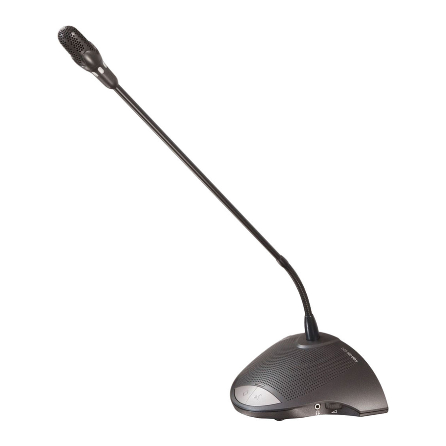
CCS 900 Ultro Delegate and Chairman Unit | en Delegate and Chairman Unit Figure 4.1 The Chairman Unit (B) has the same function as a Delegate Unit (A) with the exception of a 'priority' button and the Possible-To-Speak indication. Microphone with red illuminated indicator ring, lights when the microphone is ON. -
Page 10: Installation
(4) if necessary. Connecting up to 150 units The CCS 900 Ultro can be used with up to 150 units by adding a maximum of 2 additional Control Units acting as power supply units only. Please contact your local Bosch representative for the installation instructions. -
Page 11: Locking The Extension Cable
CCS 900 Ultro Installation | en Locking the extension cable Figure 5.3 Cable locking clamps can be used in combination with the extension cables to prevent accidental disconnection. Connecting an external microphone Figure 5.4 Put the external microphone (2) connector in the microphone input of the CU (1). Adjust the sensitivity by use of the gain control (3). -
Page 12: Connecting A Wireless Microphone
| Installation CCS 900 Ultro Connecting a wireless microphone Figure 5.5 Connecting a wireless microphone to the external microphone input is possible with the included 50dB attenuator. This way of connection allows interruption of the wireless microphone by the chairman's priority button. -
Page 13: Connecting A Pa-System Or Other External Equipment
CAUTION! Never try to make a direct connection between the telephone network and the CCS 900 Ultro discussion system. Bosch Security Systems B.V. Installation and Operating Manual... -
Page 14: Connecting An Equalizer
| Installation CCS 900 Ultro Connecting an equalizer Figure 5.9 Put the insertion switch (3) in position "0" and connect the cabling (2) of the (mono) equalizer (4) to the insertion input and output of the CU (1). Switch (3) must be in position "1"... -
Page 15: Connecting A Usb Cable
CCS 900 Ultro Installation | en 5.11 Connecting a USB cable Use the optional USB cable to connect the CU (1) to a PC. Data can then be downloaded from the CU to the PC (CCS-CURD only). See section 7 for more information. -
Page 16: Operation
| Operation CCS 900 Ultro Operation Testing the connection of the Delegate and Chairman Units Figure 6.1 Put the mode selector in the test position, all light-ring indicators and red LEDs of the Delegate and Chairman Units must lit if properly connected. -
Page 17: Possible-To-Speak
CCS 900 Ultro Operation | en Possible-To-Speak Figure 6.3 LED (A) in figure 6.3 shows Possible-To-Speak. When the LED has the white color this indicates the microphone can be switched on. When the microphone is switched on the color of the LED will change to red. If the maximum number of active microphones in the system is reached the LED will be off and the microphone can not be switched on. -
Page 18: Using The Priority Button
| Operation CCS 900 Ultro Using the priority button Figure 6.5 Pressing the priority button of the Chairman Unit (Figure 6.5 “1”) may be indicated by a chime tone and will deactivate all active Delegate Units and activates the chairman microphone (Figure 6.5 “2”). -
Page 19: Open Mode
CCS 900 Ultro Operation | en Open mode Figure 6.7 Select the max. number (1, 2, 3 or 4) of delegate microphones which can be active at the same time. NOTICE! Chairmen can always switch on and off their microphones and are not included in the maximum number. -
Page 20: Override Mode
| Operation CCS 900 Ultro Override mode Figure 6.9 Each time a delegate presses the microphone button on a Delegate Unit, it will override the currently active Delegate Unit. So only one delegate microphone is active at the same time. -
Page 21: Volume Control Of The Delegate And Chairman Units
CCS 900 Ultro Operation | en 6.11 Volume control of the Delegate and Chairman Units Figure 6.11 Turn the volume control (1) to set the volume of the loudspeakers of the Delegate and Chairman Units (2). Adjust for maximum level without feedback. In the fully counterclockwise position all loudspeakers are muted. -
Page 22: Monitoring Volume Control
| Operation CCS 900 Ultro 6.13 Monitoring volume control Figure 6.13 Use the built-in loudspeaker or a headphone to monitor the discussion. Adjust the volume using the monitoring volume control. The maximum level is controlled by the setting of the volume control for Delegate and Chairman Units. -
Page 23: Built-In Mp3 Recorder (Ccs-Curd Only)
CCS 900 Ultro Built-in MP3 recorder (CCS-CURD only) | en Built-in MP3 recorder (CCS-CURD only) Introduction NOTICE! Connect the Control Unit at least ones every 6 months to the mains supply for 24 hours to keep the MP3 back-up battery charged. -
Page 24: Overview
| Built-in MP3 recorder (CCS-CURD only) CCS 900 Ultro Overview 7.2.1 User display The user display has five soft buttons for operating the MP3 recorder (see following figure). Figure 7.1 Overview of user display and buttons Soft button 1... -
Page 25: Start-Up Screen
CCS 900 Ultro Built-in MP3 recorder (CCS-CURD only) | en 7.2.3 Start-up screen After powering up, the start-up screen is briefly displayed, which shows the name of the recorder, as well as the revision number of the software. The software then automatically displays the Record screen (see following figure). -
Page 26: Overview Of Set-Up Icons
| Built-in MP3 recorder (CCS-CURD only) CCS 900 Ultro 7.3.1 Overview of set-up icons Table 7.2 Overview of icons for navigating set-up screens Icon Icon name Function of icon Next (displayed at Go to next set-up screen. This icon is also displayed at the... -
Page 27: Deleting Files
CCS 900 Ultro Built-in MP3 recorder (CCS-CURD only) | en 7.3.2 Deleting files Use this option to delete files. Press the up or down button to select the file to delete. The filename will change on the display as the button is pressed. -
Page 28: Setting The Date And Time
| Built-in MP3 recorder (CCS-CURD only) CCS 900 Ultro 7.3.3 Setting the date and time NOTICE! To change settings in the set-up mode, you must follow the programmed sequence of events (there is no back button). To exit the set-up mode at any time, press the change mode button (button 1 at the left-side of the display). -
Page 29: Continuous Recording
CCS 900 Ultro Built-in MP3 recorder (CCS-CURD only) | en 7.3.5 Continuous recording NOTICE! If more than 50 Delegate Units are connected (by using additional Control Units), the option “record when one or more microphones are active” may not work correctly (also see section 5.2). -
Page 30: Record
| Built-in MP3 recorder (CCS-CURD only) CCS 900 Ultro Record Use the record mode to record discussion. Before recording, make sure the SD card is inserted into the slot to the right of the display, or the unit is set to internal recording. -
Page 31: Making A Recording
CCS 900 Ultro Built-in MP3 recorder (CCS-CURD only) | en 7.4.2 Making a recording Refer to figure 7.1. Make a recording as follows: Press the change mode button to select the record mode. When selected, the record icon is shown in the top right-hand corner of the display. -
Page 32: Pre-Listen And Playback
| Built-in MP3 recorder (CCS-CURD only) CCS 900 Ultro Pre-listen and Playback Refer to figure 7.1. Pre-listen and Playback are almost the same. The difference between these two modes is described below: Pre-listen Use the pre-listen mode to listen to discussion before playing it back to the floor. The audio signal is present at the monitor loudspeaker or the headphones, if connected. -
Page 33: Pre-Listening To And Playing Back Files
CCS 900 Ultro Built-in MP3 recorder (CCS-CURD only) | en 7.5.2 Pre-listening to and playing back files Refer to figure 7.1 To pre-listen to or playback files: Press the change mode button (1) to select the required mode. The pre-listen or playback icon is shown in the top right-hand corner of the display, depending on the mode selected. -
Page 34: Troubleshooting
| Troubleshooting CCS 900 Ultro Troubleshooting Problem Possible cause Solution Temporary no Trunk-line overload. Reduce load on the trunk-lines microphone reaction, and by reducing the number of units, no sound or distorted and/or the length of the trunk sound from unit cables. - Page 35 CCS 900 Ultro Troubleshooting | en Problem Possible cause Solution The SD card is incompatible. Use a PC to format the SD card. Use FAT or FAT32. Note: NTFS is incompatible. Notice: SD cards larger than 2 GB are not supported.
-
Page 36: Technical Data
| Technical data CCS 900 Ultro Technical data System Electrical and Electro-Acoustical Characteristics 9.1.1 The Control Unit (CU) Mains voltage 100 - 240 Vac ± 10%, 50/60 Hz Current consumption max. 0.9 A (100 Vac) - 0.3 A (240 Vac) - Page 37 Number of Delegate / Chairman Units connected to CU - Maximum in total - Maximum per trunk output - Maximum trunk length using 100 m (328 ft.) CCS 900 Ultro standard cabling Table 9.1 Recording capacity Recording capacity Card size Internal...
-
Page 38: Combined Units
| Technical data CCS 900 Ultro 9.1.2 Combined Units Delegate microphones with transmission links to delegate headphones and auxiliary outputs. Frequency response 25 Hz - 12.5 kHz tolerances according to IEC 60914 standard Total harmonic distortion at overload: - at nominal input level (85 dB <... -
Page 39: General Data
CCS 900 Ultro Technical data | en General data 9.3.1 System Environmental Conditions Temperature range: - Storage and transport -20 to +70°C (-4 to +158°F) - Operational +5 to +45°C (+41 to 113°F) Ambient humidity: - Operational 20% - 95% RH... -
Page 40: Equipment Range
| Technical data CCS 900 Ultro 9.3.2 Equipment Range Control and power supply unit CCS-CU CCS-CUD (with Digital Acoustic Feedback Suppression) CCS-CURD (with recording and Digital Acoustic Feedback Suppression) 19" rack mounting set LBB 3311/00 Bracket for flush mounting Can be made locally according to the illustrations in chapter 10.2... -
Page 41: Appendix
CCS 900 Ultro Appendix | en Appendix 10.1 Pin Configuration Figure 10.1 Connector overview 10.1.1 Trunk Connections (A) Audio contribution line Audio distribution line Control line 1 Control line 2 V+ supply V- supply 10.1.2 External Microphone (XLR) (B) GND (0V, phantom supply) -
Page 42: Schematics Of Connectors Lbb 3316/00
| Appendix CCS 900 Ultro 10.1.6 Schematics of connectors LBB 3316/00 Figure 10.2 Connector pin connections Pin number Color White Shield Violet Yellow Green Blue IOM_CCS900 | V1.0 | 2010.06 Installation and Operating Manual Bosch Security Systems B.V. -
Page 43: Mounting Instructions
CCS 900 Ultro Appendix | en 10.2 Mounting Instructions The CU can be attached in three different ways: – In a 19" rack making use of the 19" rack mounting set LBB 3311/00. Place a blank 1HU panel above the CU to have sufficient space for cable connections. -
Page 44: Bracket For Flush Mounting
| Appendix CCS 900 Ultro 10.3 Bracket for Flush Mounting The drawing below gives the necessary information how to make a bracket for flush mounting the CU into a table. Figure 10.5 IOM_CCS900 | V1.0 | 2010.06 Installation and Operating Manual... - Page 46 Bosch Security Systems B.V. Kapittelweg 10 4800 RA Breda The Netherlands www.boschsecurity.com © Bosch Security Systems B.V., 2010...