Table of Contents
Advertisement
Quick Links
Download this manual
See also:
Manual
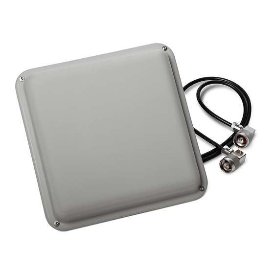
Cisco Aironet 5-GHz 14-dBi Directional Antenna
(AIR-ANT5114P2M-N)
This document outlines the specifications for the Cisco Aironet AIR-ANT5114P2M-N 5-GHz 14-dBi
2-Port Directional antenna with N-type connectors and provides instructions for mounting it. The
antenna operates in the 5-GHz frequency band and is designed for use in outdoor environments.
The following information is provided in this document.
•
Technical Specifications, page 2
System Requirements, page 3
•
Safety Precautions, page 3
•
•
Installation Guidelines, page 4
Installing the Antenna, page 5
•
Obtaining Documentation and Submitting a Service Request, page 13
•
Cisco Systems, Inc.
www.cisco.com
Advertisement
Table of Contents

Related Manuals for Cisco Aironet AIR-ANT5114P2M-N


Summary of Contents for Cisco Aironet AIR-ANT5114P2M-N
- Page 1 Cisco Aironet 5-GHz 14-dBi Directional Antenna (AIR-ANT5114P2M-N) This document outlines the specifications for the Cisco Aironet AIR-ANT5114P2M-N 5-GHz 14-dBi 2-Port Directional antenna with N-type connectors and provides instructions for mounting it. The antenna operates in the 5-GHz frequency band and is designed for use in outdoor environments.
-
Page 2: Technical Specifications
7.8 in. (19.8 cm) Width 7.8 in. (19.8 cm) Height 1.2 in. (3 cm) Weight 21.6 oz. (0.61 kg) Operating temperature range –40°F to 131°F (–40°C to 55°C) Elevation and Azimuth Plane Patterns Cisco Aironet 5-GHz 14-dBi Directional Antenna (AIR-ANT5114P2M-N) 78-20958-01... -
Page 3: System Requirements
System Requirements System Requirements This antenna is designed for use with Cisco Aironet access points and bridges but can be used with any 5-GHz Cisco Aironet radio device that uses an N-male connector. Safety Precautions Installation of this antenna near power lines is dangerous. For your safety, follow the installation Warning directions. -
Page 4: Installation Guidelines
A thick metal wall causes signals to reflect, causing poor penetration. • Install the antenna away from 5-GHz cordless phones. These products can cause signal interference because they operate in the same frequency range as the device your antenna is connected to. Cisco Aironet 5-GHz 14-dBi Directional Antenna (AIR-ANT5114P2M-N) 78-20958-01... -
Page 5: Site Selection
5/16-in nut driver or flat head screwdriver for pipe clamps • The following sections contain typical procedures for installing the antenna on a pole. Your installation may vary. Before you begin, you may want to refer to Figure Cisco Aironet 5-GHz 14-dBi Directional Antenna (AIR-ANT5114P2M-N) 78-20958-01... -
Page 6: Mounting On A Pole
Attach antenna mount bracket to the back of the antenna as shown applying a maximum nut-tightening Step 2 torque of 55 in-lbf (6.2 Nm). Figure 1 Attaching Antenna Mount Bracket Antenna mount bracket 1/4-in. spring lock washer 1/4-in. flat washer 1/4-in. 20 hex nut Cisco Aironet 5-GHz 14-dBi Directional Antenna (AIR-ANT5114P2M-N) 78-20958-01... - Page 7 Attach elevation adjustable bracket as shown and loosely secure hardware. The carriage bolt square holes Step 3 must be on the inside. Figure 2 Attaching Elevation Adjustable Bracket Elevation adjustable bracket 1/4-in. spring lock washer 1/4-in. 20x3/4 carriage bolt 1/4-in. 20 hex nut 1/4-in. flat washer Cisco Aironet 5-GHz 14-dBi Directional Antenna (AIR-ANT5114P2M-N) 78-20958-01...
- Page 8 Attach azimuth adjustable bracket to pipe routing band clamps as shown. Tighten the pipe clamps to a Step 4 torque of 43-51 in-lbf (4.9-5.8 Nm). Figure 3 Attaching Azimuth Adjustable Bracket Azimuth adjustable bracket Pipe clamps Cisco Aironet 5-GHz 14-dBi Directional Antenna (AIR-ANT5114P2M-N) 78-20958-01...
- Page 9 Attach antenna assembly to azimuth bracket on pipe. Step 5 Figure 4 Attaching Antenna Assembly 1/4-in. flat washer Elevation adjustable bracket 1/4-in. spring lock washer 1/4-in. 20x3/4 carriage bolt 1/4-in. 20 hex nut Cisco Aironet 5-GHz 14-dBi Directional Antenna (AIR-ANT5114P2M-N) 78-20958-01...
- Page 10 +/–45 degrees azimuth and +/–60 degrees elevation. Figure 5 Adjusting Antenna Position Note Cisco recommends grounding the antenna. See the “Grounding the Antenna” section on page 13 for details. Cisco Aironet 5-GHz 14-dBi Directional Antenna (AIR-ANT5114P2M-N) 78-20958-01...
- Page 11 For more information on mounting the antenna with the optional mounting bracket, refer to Installing Antenna Brackets on Cisco 1550 Series Outdoor Mesh Access Points.
-
Page 12: Antenna Cable Information
Antenna Cable Information If the antenna is used with the Cisco 1552CU or 1552EU access point, the port A of the antenna must be connected to port 1 of the access point, port B of the antenna must be connected to port 3 of the access point, and port 2 of the access point must be capped with the cap enclosed with the antenna. -
Page 13: Grounding The Antenna
What’s New in Cisco Product Documentation at: http://www.cisco.com/en/US/docs/general/whatsnew/whatsnew.html. Subscribe to What’s New in Cisco Product Documentation, which lists all new and revised Cisco technical documentation, as an RSS feed and deliver content directly to your desktop using a reader application. The RSS feeds are a free service. - Page 14 Installing the Antenna Cisco and the Cisco logo are trademarks or registered trademarks of Cisco and/or its affiliates in the U.S. and other countries. To view a list of Cisco trademarks, go to this URL: www.cisco.com/go/trademarks. Third-party trademarks mentioned are the property of their respective owners.