Table of Contents
Advertisement
Quick Links
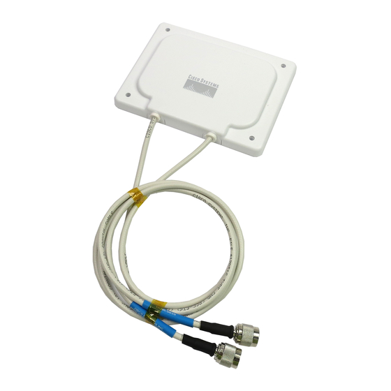
Cisco Aironet 7-dBi Diversity Patch Antenna
(AIR-ANT5170P-R)
This document outlines the specifications, describes the AIR-ANT5170P-R 7-dBi diversity patch
antenna, and provides instructions for mounting it. The antenna operates in the 5-GHz frequency range
and is designed for use in both indoor and outdoor environments.
The following information is provided in this document.
Technical Specifications, page 2
•
System Requirements, page 3
•
Installation Guidelines, page 4
•
Installing the Antenna, page 5
•
Obtaining Documentation and Submitting a Service Request, page 7
•
Corporate Headquarters:
Cisco Systems, Inc., 170 West Tasman Drive, San Jose, CA 95134-1706 USA
Copyright © 2005 Cisco Systems, Inc. All rights reserved.
Advertisement
Table of Contents

Related Manuals for Cisco AIR-ANT5170P-R - Aironet Diversity Patch


Summary of Contents for Cisco AIR-ANT5170P-R - Aironet Diversity Patch
- Page 1 (AIR-ANT5170P-R) This document outlines the specifications, describes the AIR-ANT5170P-R 7-dBi diversity patch antenna, and provides instructions for mounting it. The antenna operates in the 5-GHz frequency range and is designed for use in both indoor and outdoor environments. The following information is provided in this document.
-
Page 2: Technical Specifications
Weight 8 oz (0.2 kg) Operating temperature range –22°F - 158°F (–30°C -70°C) Storage temperature range –40°F - 185°F (–40°C - 85°C) Wind rating 80 mph (128.7 kph) H-Plane Pattern E-Plane Pattern Cisco Aironet 7-dBi Diversity Patch Antenna (AIR-ANT5170P-R) 78-16468-02... -
Page 3: System Requirements
System Requirements System Requirements This antenna is designed for use with Cisco Aironet access points and bridges but can be used with any 5-GHz Cisco Aironet radio device that uses an RP-TNC connector. Safety Precautions Installation of this antenna near power lines is dangerous. For your safety, follow the installation Warning directions. -
Page 4: Installation Guidelines
Each person should be assigned to a specific task, and should know what to do and when to do it. One person should be in charge of the operation to issue instructions and watch for signs of trouble. -
Page 5: Site Selection
Generally, the higher an antenna is above the ground, the better it performs. Good practice is to install your antenna about 5 to 10 ft (1.5 to 3 m) above the roof line and away from all power lines and obstructions. -
Page 6: Antenna Cable Information
Use the antenna as a template to mark the locations of the four mounting holes. Step 2 Use a drill and a 3/16-in. (4.7 mm) drill bit to drill four holes at the locations you marked in Step 2. Step 3 Start a plastic anchor into each hole. -
Page 7: Grounding The Antenna
Mount the antenna discharge unit as close as possible to where the lead-in wire enters the building. Step 4 Drill a hole in the building’s wall as close as possible to the equipment to which you will connect the lead-in cable. - Page 8 Cisco and the Cisco Logo are trademarks of Cisco Systems, Inc. and/or its affiliates in the U.S. and other countries. A listing of Cisco's trademarks can be found at www.cisco.com/go/trademarks. Third party trademarks mentioned are the property of their respective owners. The use of the word partner does not imply a partnership relationship between Cisco and any other company.