Table of Contents
Advertisement
Quick Links
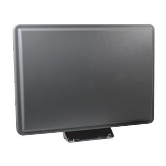
Cisco Aironet Six-Element Dual-Band
MIMO Patch Array Antenna
(AIR-ANT25137NP-R)
June 3, 2011
This document describes the AIR-ANT25137NP-R antenna and provides
instructions for mounting it. The antenna is a six-element, dual-band,
multiple-input and multiple-output (MIMO), patch array antenna that operates in
the 2.4- and 5-GHz frequency ranges. The antenna is designed for use in indoor
and outdoor environments with Cisco Aironet 3502P Access Points.
The following information is provided in this document:
Technical Specifications, page 2
•
System Requirements, page 6
•
Safety Instructions, page 7
•
Installation Notes, page 8
•
Choosing a Mounting Location, page 9
•
Installing the Antenna, page 9
•
Painting the Antenna, page 14
•
•
Americas Headquarters:
Cisco Systems, Inc., 170 West Tasman Drive, San Jose, CA 95134-1706 USA
Advertisement
Table of Contents

Related Manuals for Cisco Aironet AIR-ANT25137NP-R


Summary of Contents for Cisco Aironet AIR-ANT25137NP-R
-
Page 1: Table Of Contents
Choosing a Mounting Location, page 9 • Installing the Antenna, page 9 • Painting the Antenna, page 14 • Obtaining Documentation and Submitting a Service Request, page 16 • Americas Headquarters: Cisco Systems, Inc., 170 West Tasman Drive, San Jose, CA 95134-1706 USA... -
Page 2: Technical Specifications
Environmental Water: IP65, dust and jetting Ratings water immunity Ice: Mil-810F, Method 521.2 Wind: 100 mph operational Operating Temperature: -30 to 70 degrees C (-22 to 158 degrees F) Cisco Aironet Six-Element Dual-Band MIMO Patch Array Antenna (AIR-ANT25137NP-R) OL-23461-01... -
Page 3: Radiation Patterns
Technical Specifications Radiation Patterns 2.4-GHz Antenna Patterns 2.4-GHz Antenna Cable A 2.4-GHz Antenna Cable B 2.4-GHz Antenna Cable C Cisco Aironet Six-Element Dual-Band MIMO Patch Array Antenna (AIR-ANT25137NP-R) OL-23461-01... - Page 4 Technical Specifications 5-GHz Antenna Patterns 5-GHz Antenna Cable A 5-GHz Antenna Cable B 5-GHz Antenna Cable C Cisco Aironet Six-Element Dual-Band MIMO Patch Array Antenna (AIR-ANT25137NP-R) OL-23461-01...
- Page 5 Technical Specifications Antenna and Bracket Dimensions Figure 1 Figure 2 show the overal dimensions of the antenna and bracket. Figure 1 Rear View of Antenna and Bracket Cisco Aironet Six-Element Dual-Band MIMO Patch Array Antenna (AIR-ANT25137NP-R) OL-23461-01...
-
Page 6: System Requirements
Side View of Antenna and Bracket System Requirements This antenna is designed for use with Cisco Aironet 3502P Access Points. The antenna can be mounted on a wall, ceiling, or pole with a maximum diameter of 3 inches (7.62 cm). -
Page 7: Safety Instructions
Call your local power company or building maintenance organization if you • are unsure about cables close to your mounting location. Cisco Aironet Six-Element Dual-Band MIMO Patch Array Antenna (AIR-ANT25137NP-R) OL-23461-01... -
Page 8: Installation Notes
Install the antenna away from microwave ovens and 2-GHz cordless phones. • These products can cause signal interference because they operate in the same frequency range as the device to which your antenna is connected. Cisco Aironet Six-Element Dual-Band MIMO Patch Array Antenna (AIR-ANT25137NP-R) OL-23461-01... -
Page 9: Choosing A Mounting Location
The fasteners and mounting surface should be capable of maintaining a Note minimum pullout force of 150 pounds (68 kg) to support the weight of the antenna and bracket plus the potential wind loading on the antenna. Cisco Aironet Six-Element Dual-Band MIMO Patch Array Antenna (AIR-ANT25137NP-R) OL-23461-01... - Page 10 To mount the antenna on a pole or mast, you will need these supplies: Two U-bolts • Cisco recommends using a guillotine-style U-bolt or a U-bolt with a Note notched, toothed backing plate to ensure proper support and permanent positioning.
- Page 11 Use a 10-mm wrench to loosen the adjustment bolts and the pivot bolts (Figure 4). Azimuth angle can be adjusted ±25 degrees and elevation can be adjusted ±60 degrees. Cisco Aironet Six-Element Dual-Band MIMO Patch Array Antenna (AIR-ANT25137NP-R) OL-23461-01...
- Page 12 After you adjust the antenna position, tighten the adjustment bolts and the pivot Step 9 bolts. Tighten all bolts to 7 ± 0.5 lb-ft. (9.5 Nm). Connect the antenna cable to the access point. Step 10 Figure 4 Azimuth and Elevation Adjustment Cisco Aironet Six-Element Dual-Band MIMO Patch Array Antenna (AIR-ANT25137NP-R) OL-23461-01...
- Page 13 Mounting on a Pole or Mast The antenna can be mounted on a pole or mast using two U-bolts (not provided). Cisco recommends using a guillotine-style U-bolt or a U-bolt with a Note notched, toothed backing plate to ensure proper support and permanent positioning.
-
Page 14: Painting The Antenna
Painting the Antenna Suggested Cable Cisco recommends a high-quality, low-loss cable for use with the antenna. Coaxial cable loses efficiency as the frequency increases, resulting in signal loss. Note The cable should be kept as short as possible because cable length also determines the amount of signal loss (the longer the run, the greater the loss). - Page 15 Painting the Antenna Figure 5 Vent on Rear of Antenna Cisco Aironet Six-Element Dual-Band MIMO Patch Array Antenna (AIR-ANT25137NP-R) OL-23461-01...
-
Page 16: Obtaining Documentation And Submitting A Service Request
The RSS feeds are a free service and Cisco currently supports RSS Version 2.0. Cisco and the Cisco Logo are trademarks of Cisco Systems, Inc. and/or its affiliates in the U.S. and other countries. A listing of Cisco's trademarks can be found at www.cisco.com/go/trademarks. Third party trademarks mentioned are the property of their respective owners.