Table of Contents
Advertisement
Quick Links
- 1 Software and Firmware Use
- 2 Front Panel Description
- 3 Installation Preparations
- 4 Install the Cable Modem
- 5 Chapter 3 Operation of Front Panel Indicators
- 6 Initial Power Up, Calibration, and Registration (Ac Power Applied)
- 7 Chapter 5 Troubleshooting the Docsis Cable Modem
- 8 Common Troubleshooting Issues
- Download this manual
Advertisement
Table of Contents
Troubleshooting

Related Manuals for Cisco DPC3208


Summary of Contents for Cisco DPC3208
- Page 1 4027620 Rev A Cisco Model DPC3208 and EPC3208 8x4 DOCSIS 3.0 Cable Modem User Guide...
- Page 3 Please Read Important Please read this entire guide. If this guide provides installation or operation instructions, give particular attention to all safety statements included in this guide.
-
Page 4: Software And Firmware Use
Trademark Acknowledgments Cisco and the Cisco logo are trademarks or registered trademarks of Cisco and/or its affiliates in the U.S. and other countries. A listing of Cisco's trademarks can be found at www.cisco.com/go/trademarks. DOCSIS is a registered trademark of Cable Television Laboratories, Inc. - Page 5 Copyright © 2011 Cisco and/or its affiliates. All rights reserved. Printed in the United States of America. Information in this publication is subject to change without notice. No part of this publication may be reproduced or transmitted in any form, by photocopy,...
-
Page 6: Notice To Installers
Notice to Installers The servicing instructions in this notice are for use by qualified service personnel only. To reduce the risk of electric shock, do not perform any servicing other than that contained in the operating instructions, unless you are qualified to do so. Notice à... -
Page 7: Aviso A Los Instaladores De Sistemas Catv
Mitteilung für CATV-Techniker Die in dieser Mitteilung aufgeführten Wartungsanweisungen sind ausschließlich für qualifiziertes Fachpersonal bestimmt. Um die Gefahr eines elektrischen Schlags zu reduzieren, sollten Sie keine Wartungsarbeiten durchführen, die nicht ausdrücklich in der Bedienungsanleitung aufgeführt sind, außer Sie sind zur Durchführung solcher Arbeiten qualifiziert. Aviso a los instaladores de sistemas CATV Las instrucciones de reparación contenidas en el presente aviso son para uso exclusivo por parte de personal de mantenimiento cualificado. -
Page 9: Table Of Contents
Contents IMPORTANT SAFETY INSTRUCTIONS United States FCC Compliance CE Compliance About This Guide xviii Chapter 1 Introducing the DOCSIS Cable Modem Introduction ..........................2 What's In the Carton? ......................4 Front Panel Description ......................5 Back Panel Description ......................7 Chapter 2 Installing the DOCSIS Cable Modem Installation Preparations ....................... - Page 10 Contents Chapter 6 Customer Information Customer Support ........................42 Index 4027620 Rev A...
-
Page 11: Important Safety Instructions
IMPORTANT SAFETY INSTRUCTIONS IMPORTANT SAFETY INSTRUCTIONS Read these instructions. Keep these instructions. Heed all warnings. Follow all instructions. Do not use this apparatus near water. Clean only with dry cloth. Do not block any ventilation openings. Install in accordance with the manufacturer's instructions. - Page 12 IMPORTANT SAFETY INSTRUCTIONS Protect the Product from Lightning In addition to disconnecting the AC power from the wall outlet, disconnect the signal inputs. Verify the Power Source from the On/Off Power Light When the on/off power light is not illuminated, the apparatus may still be connected to the power source.
- Page 13 IMPORTANT SAFETY INSTRUCTIONS The batteries may contain perchlorate, a known hazardous substance, so special handling and disposal of this product might be necessary. For more information about perchlorate and best management practices for perchlorate-containing substance, see www.dtsc.ca.gov/hazardouswaste/perchlorate Provide Ventilation and Select a Location ...
- Page 14 IMPORTANT SAFETY INSTRUCTIONS 1. Do not use this product near water, for example, near a bath tub, wash bowl, kitchen sink or laundry tub, in a wet basement or near a swimming pool. 2. Avoid using a telephone (other than a cordless type) during an electrical storm. There may be a remote risk of electric shock from lightning.
- Page 15 IMPORTANT SAFETY INSTRUCTIONS 4027620 Rev A...
-
Page 16: United States Fcc Compliance
Consult the service provider or an experienced radio/television technician for help. Any changes or modifications not expressly approved by Cisco Systems, Inc., could void the user's authority to operate the equipment. The information shown in the FCC Declaration of Conformity paragraph below is a requirement of the FCC and is intended to supply you with information regarding the FCC approval of this device. - Page 17 United States FCC Compliance This system has been evaluated for RF exposure for humans in reference to ANSI C 95.1 (American National Standards Institute) limits. The evaluation was based in accordance with FCC OET Bulletin 65C rev 01.01 in compliance with Part 2.1091 and Part 15.27. The minimum separation distance from the antenna to general bystander is 7.9 inches (20 cm) to maintain compliance.
- Page 19 United States FCC Compliance 4027620 Rev A xiii...
-
Page 20: Ce Compliance
This declaration is only valid for configurations (combinations of software, firmware and hardware) supported or provided by Cisco Systems for use within the EU. The use of software or firmware not supported or provided by Cisco Systems may result in the equipment no longer being compliant with the regulatory requirements. - Page 21 Note: The full declaration of conformity for this product can be found in the Declarations of Conformity and Regulatory Information section of the appropriate product hardware installation guide, which is available on Cisco.com. The following standards were applied during the assessment of the product against the requirements of the Directive 1999/5/EC: ...
- Page 23 CE Compliance 4027620 Rev A xvii...
-
Page 24: About This Guide
About This Guide About This Guide Introduction Welcome. This guide provides instructions and recommendations for placing, installing, configuring, operating, maintaining, and troubleshooting the DPC3208 and EPC3208 DOCSIS Cable Modems. Purpose This guide covers the following product models: DPC3208 DOCSIS Cable Modem ... -
Page 25: Chapter 1 Introducing The Docsis Cable Modem
Chapter 1 Introducing the DOCSIS Cable Modem Introduction This chapter provides an overview of cable modem features, indicators, and connectors to help you become familiar with the cable modem and the benefits it offers. This chapter also lists the accessories and equipment that are provided with the cable modem so you can verify that you received all of these items. -
Page 26: Introduction
Chapter 1 Introducing the DOCSIS Cable Modem Introduction Welcome to the exciting world of high-speed Internet and high-quality digital telephone service. Your new cable modem meets industry standards for high-speed data connectivity along with reliable digital telephone service. The cable modem delivers data, voice and wired (Ethernet) gateway capabilities to connect a variety of devices in the home or small office and support high-speed data access and cost- effective voice services, all in one device. - Page 27 Introduction Dual color LED status indicators on the front panel provide an informative and easy-to-understand display that indicates the cable modem operational status Rugged electronic components for long-term reliability Optional battery powered backup on loss of AC power Management ...
-
Page 28: What's In The Carton
Chapter 1 Introducing the DOCSIS Cable Modem What's In the Carton? When you receive your cable modem, you should check the equipment and accessories to verify that each item is in the carton and that each item is undamaged. The carton contains the following items: One AC power adapter with power cord (Image may vary from actual One DPC3208 or EPC3208 DOCSIS... -
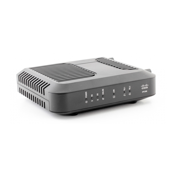
Page 29: Front Panel Description
Front Panel Description Front Panel Description The front panel of your cable modem provides LED status indicators that indicate how well and at what state your cable modem is operating. See Operation of Front Panel Indicators (on page 21), for more information on front panel LED status indicator functions. - Page 30 Chapter 1 Introducing the DOCSIS Cable Modem power (without AC power). Most LEDs are disabled if the unit is operating on battery power. In this mode, the POWER LED blinks to indicate that the unit is operating under battery power. The cable modem should only run on battery power when AC power has failed.
-
Page 31: Back Panel Description
Back Panel Description Back Panel Description The following illustration identifies the back panel components on the DPC3208 and EPC3208 cable modems. Descriptions for each component follow the illustration. EPC3208 (shown without battery backup DPC3208 (shown with battery backup capability) capability) ON/OFF SWITCH (Provided only on products that carry the CE mark)—... -
Page 33: Chapter 2 Installing The Docsis Cable Modem
Chapter 2 Installing the DOCSIS Cable Modem Introduction This chapter describes how to properly install the cable modem and to connect the cable modem to a computer and other devices. In This Chapter Installation Preparations ..............10 Install the Cable Modem ..............18 4027620 Rev A... -
Page 34: Installation Preparations
Chapter 2 Installing the DOCSIS Cable Modem Installation Preparations Before installing the cable modem make sure that your system meets or exceeds the requirements listed in this section. Also make sure that your have prepared your home and home devices as described in this section. What Are the System Requirements for Internet Service? To ensure that your cable modem operates efficiently for high-speed Internet service, you must have an Internet-capable PC, Mac, or Internet appliance equipped with an... - Page 35 Installation Preparations The maximum number of telephone devices connected to each RJ-11 port is limited by the total Ringing Load of the telephone devices that are connected. Many telephone devices are marked with a Ringer Equivalent Number (REN). Each telephone port on the cable modem can support up to a 5 REN load. The sum of the REN load on all of the telephone devices attached to each port must not exceed 5 REN.
- Page 36 Chapter 2 Installing the DOCSIS Cable Modem Refer to one of the following topics to learn more about the types of service accounts that you may need to establish. High-Speed Internet Access Account If you do not have a high-speed Internet access account, your service provider will set up your account and become your Internet Service Provider (ISP).
- Page 37 Installation Preparations Telephone Service You will need to establish a telephone account with your local service provider to use your cable modem for telephone service. When you contact your service provider, you may be able to transfer your existing telephone numbers. If not, then your cable telephony service provider will assign a new telephone number to enable your voice service(s).
- Page 38 Chapter 2 Installing the DOCSIS Cable Modem Installing the Battery Installing the battery requires no tools. Follow these instructions to install the battery. WARNING: Fully charged high-capacity rechargeable batteries should be handled with care. Replace only with the battery recommended by the manufacturer. Do not disassemble it or attempt to recharge the battery outside the system.
- Page 39 Installation Preparations How Do I Mount the Cable Modem on a Wall? (Optional) If you wish, you can mount the cable modem to a wall. This section describes how to mount the cable modem to a wall, and includes a list of equipment you will need along with suggestions for choosing an appropriate place to mount the cable modem.
- Page 40 Chapter 2 Installing the DOCSIS Cable Modem Location and Dimensions of the Wall-Mounting Slots The following illustration shows the location and dimensions of the wall-mounting slots on the bottom of the cable modem. Use this illustration as a guide for mounting the cable modem to the wall.
- Page 41 Installation Preparations Note: Image not to scale. Mounting the Cable Modem on a Wall Using a drill with a 3/16-inch bit, drill two holes at the same height and 4 inches apart. Note: The preceding graphic illustrates the location of the mounting holes on the back of the cable modem.
-
Page 42: Install The Cable Modem
Chapter 2 Installing the DOCSIS Cable Modem Install the Cable Modem This section describes how to connect your cable modem to support the services that the cable modem offers. Connect Devices to the Cable Modem The following illustration shows all of the possible connections that can be made to your cable modem for various services. - Page 43 Install the Cable Modem WARNING: To prevent possible damage to equipment, disconnect any other telephone service before connecting your cable modem to the same wires. Hazardous electrical voltages can exist on the telephone, Ethernet, or coax cable wiring. Be sure to disconnect AC power from all devices while installing your service.
- Page 44 Chapter 2 Installing the DOCSIS Cable Modem Locate the AC power adapter provided with your cable modem. Connect the barrel connector end of the power adapter into the power input on the back of the cable modem. Then, plug the AC power adapter into an AC outlet to power- up the cable modem.
-
Page 45: Chapter 3 Operation Of Front Panel Indicators
Chapter 3 Operation of Front Panel Indicators Introduction This section describes the behavior of the front panel indicators when the cable modem is first powered up, during normal operations, and in special conditions. In This Chapter Initial Power Up, Calibration, and Registration (AC Power applied) .................... -
Page 46: Initial Power Up, Calibration, And Registration (Ac Power Applied)
Chapter 3 Operation of Front Panel Indicators Initial Power Up, Calibration, and Registration (AC Power applied) The following chart illustrates the sequence of steps and the corresponding appearance of the cable modem front panel LED status indicators during power up, calibration, and registration on the network when AC power is applied to the cable modem. - Page 47 Initial Power Up, Calibration, and Registration (AC Power applied) LINK On or Blinking On or Blinking On or Blinking On or Blinking On or Blinking TEL 1 Blinking Blinking TEL 2 Blinking Blinking BATTERY On – When battery is charged ...
-
Page 48: Normal Operations (Ac Power Applied)
Chapter 3 Operation of Front Panel Indicators Normal Operations (AC Power Applied) The following chart illustrates the appearance of the cable modem front panel LED status indicators during normal operations when AC power is applied to the gateway. Front Panel LED Status Indicators During Normal Conditions Front Panel Indicator Normal Operations POWER... -
Page 49: Special Conditions
Special Conditions Special Conditions The following chart describes the appearance of the cable modem front panel LED status indicators during special conditions to show when you have been denied network access. Front Panel LED Status Indicators During Special Conditions Front Panel Indicator Network Access Denied POWER Slow Blinking... -
Page 51: Chapter 4 Maintaining The Battery
Chapter 4 Maintaining the Battery Introduction This chapter describes how to maintain and replace the battery that is included with the cable modem. In This Chapter Location of the Battery ................. 28 Battery Maintenance ................29 4027620 Rev A... -
Page 52: Location Of The Battery
Chapter 4 Maintaining the Battery Location of the Battery The following illustration shows the location of the battery. 4027620 Rev A... -
Page 53: Battery Maintenance
Battery Maintenance Battery Maintenance If your cable modem contains a battery backup feature, a Lithium-Ion battery provides stand-by operation in the event of an AC power failure. You can replace the battery without the use of any tools. WARNING: Fully charged high-capacity rechargeable batteries should be handled with care. - Page 54 Chapter 4 Maintaining the Battery Insert a new battery into the battery compartment. Do not force the battery into the compartment, but be sure to press the battery all the way in until it seats fully. Close the battery compartment door. The battery lock will automatically re- engage.
-
Page 55: Chapter 5 Troubleshooting The Docsis Cable Modem
Chapter 5 Troubleshooting the DOCSIS Cable Modem Introduction This chapter describes the most common issues that may occur after the cable modem is installed and provides possible solutions and tips for improved performance of the cable modem. In This Chapter ... -
Page 56: Faqs
Chapter 5 Troubleshooting the DOCSIS Cable Modem Frequently Asked Questions This section provides answers to common questions about the cable modem. How Do I Configure TCP/IP Protocol? To configure TCP/IP protocol, you need to have an Ethernet Network Interface Card (NIC) with TCP/IP communications protocol installed on your system. - Page 57 Frequently Asked Questions Click Internet Protocol (TCP/IP), and then click Properties in the Local Area Connection Properties window. Select both Obtain an IP address automatically and Obtain DNS server address automatically in the Internet Protocol (TCP/IP) Properties window, and then click OK.
- Page 58 Chapter 5 Troubleshooting the DOCSIS Cable Modem How Do I Renew the IP Address on My PC? If your PC cannot access the Internet after the cable modem is online, it is possible that your PC did not renew its IP address. Follow the appropriate instructions in this section for your operating system to renew the IP address on your PC.
- Page 59 Frequently Asked Questions 11 Click Options in the TCP/IP window, and then click Active in the TCP/IP Options window. Note: In some cases, the Load only when needed option does not appear. If it appears, select the option. A check mark appears in the option. 12 Verify that the Use 802.3 option located in the upper-right corner of the TCP/IP window is not selected.
- Page 60 Chapter 5 Troubleshooting the DOCSIS Cable Modem Can I Use my Existing Phone Number with the Cable Modem? Telephone numbers are portable in some areas. Contact your telephone service provider for more information about using an existing telephone number. How Many Telephones Can I Connect? The RJ-11 telephone-style connectors on the cable modem can each provide telephone service to multiple telephones, fax machines, and analog modems.
-
Page 61: Common Troubleshooting Issues
Common Troubleshooting Issues Common Troubleshooting Issues This section describes common problems and offers solutions. I don't understand the front panel status indicators See Operation of Front Panel Indicators (on page 21), for more detailed information on front panel LED status indicator operation and function. The Cable Modem does not register an Ethernet connection Try one of the following solutions: Verify that your computer has an Ethernet card and that the Ethernet driver... - Page 62 Chapter 5 Troubleshooting the DOCSIS Cable Modem working here but does not work at other locations in the home, a professional may need to diagnose and repair a problem with your telephone wiring. Verify that the telephone company has removed the previous telephone service ...
-
Page 63: Tips For Improved Performance
Tips for Improved Performance Tips for Improved Performance If your cable modem does not perform as expected, the following tips may help. If you need further assistance, contact your service provider. Verify that the plug to your cable modem AC power is properly inserted into an ... -
Page 65: Customer Information
Chapter 6 Customer Information Introduction This chapter provides contact information to obtain product support. In This Chapter Customer Support ................42 4027620 Rev A... -
Page 66: Customer Support
If you have technical questions, telephone your nearest technical support office at one of the following telephone numbers. The Americas Technical Support United States Cisco Services ® Atlanta, Georgia For Digital Broadband Delivery System products only, call: –... - Page 67 Customer Support Australia Technical Support Australia Sydney Telephone: 011 61 2 8446 5394 Fax: 011 61 2 8446 8015 Japan Japan Tokyo Technical Support Telephone: 011 81 3 5322 2067 Fax: 011 81 3 5322 1311 4027620 Rev A...
- Page 69 Index how to access • 35 surfing while watching TV • 35 unable to access • 34 accessing the Internet • 35 IP address, renewing • 34 accessories • 4 LEDs • 5, 22, 24, 25 battery charging • 29 location disposal •...
- Page 70 Index USB • 4, 35 ventilation requirements • vii Voice settings LEDs • 5, 22, 24, 25 wall mounting instructions • 17 slots • 16 4027620 Rev A...
- Page 72 This document includes various trademarks of Cisco Systems, Inc. Please see the Notices section of this document for a list of the Cisco Systems, Inc. trademarks used in this document. Product and service availability are subject to change without notice.